Sélection de la langue

Search

Sommaire du brevet 1322017 

Énoncé de désistement de responsabilité concernant l'information provenant de tiers

Une partie des informations de ce site Web a été fournie par des sources externes. Le gouvernement du Canada n'assume aucune responsabilité concernant la précision, l'actualité ou la fiabilité des informations fournies par les sources externes. Les utilisateurs qui désirent employer cette information devraient consulter directement la source des informations. Le contenu fourni par les sources externes n'est pas assujetti aux exigences sur les langues officielles, la protection des renseignements personnels et l'accessibilité.

Disponibilité de l'Abrégé et des Revendications

L'apparition de différences dans le texte et l'image des Revendications et de l'Abrégé dépend du moment auquel le document est publié. Les textes des Revendications et de l'Abrégé sont affichés :

  • lorsque la demande peut être examinée par le public;
  • lorsque le brevet est émis (délivrance).
(12) Brevet: (11) CA 1322017
(21) Numéro de la demande: 1322017
(54) Titre français: RACCORD POUR CONDUITS DE GAZ DE COMBUSTION
(54) Titre anglais: FLUE GAS CONDUIT CONNECTOR
Statut: Durée expirée - après l'octroi
Données bibliographiques
(51) Classification internationale des brevets (CIB):
  • F16L 25/00 (2006.01)
  • F16L 21/08 (2006.01)
(72) Inventeurs :
  • GREEN, LLOYD C. (Etats-Unis d'Amérique)
(73) Titulaires :
  • SELKIRK CORPORATION
(71) Demandeurs :
  • SELKIRK CORPORATION (Canada)
(74) Agent: OSLER, HOSKIN & HARCOURT LLP
(74) Co-agent:
(45) Délivré: 1993-09-07
(22) Date de dépôt: 1989-06-15
Licence disponible: S.O.
Cédé au domaine public: S.O.
(25) Langue des documents déposés: Anglais

Traité de coopération en matière de brevets (PCT): Non

(30) Données de priorité de la demande:
Numéro de la demande Pays / territoire Date
07/354 878 (Etats-Unis d'Amérique) 1989-05-22

Abrégés

Abrégé anglais


FLUE GAS CONDUIT CONNECTOR
ABSTRACT OF THE DISCLOSURE
A flue gas conduit connector for joining together the
ends of flue gas conduits by means of locking tabs on the
outer surface of one flue gas conduit which may be bent over
a locking ring or the other flue gas conduit, the ends of
the flue gas conduits being provided with complimental taper
joints and a sealing gasket to provide a leak-proof corrosion
resistant inner flue passage uncorrupted by low alloy fasteners.

Revendications

Note : Les revendications sont présentées dans la langue officielle dans laquelle elles ont été soumises.


THE EMBODIMENTS OF THE INVENTION IN WHICH AN EXCLUSIVE
PROPERTY OR PRIVILEGE IS CLAIMED ARE DEFINED AS FOLLOWS:
1. A flue gas conduit connector for joining together the
ends of first and second flue gas conduits comprising:
a first annular female tapered end joint on the end of the
first flue gas conduit,
a second complemental annular male tapered end joint on the
end of the second flue gas conduit,
a resilient sealing gasket on the outer periphery of the
second male tapered end joint,
a plurality of locking tabs secured to the outer periphery
of the first female tapered end joint and having free ends
extending substantially-horizontally outwardly therefrom at
spaced intervals therearound,
a locking ring loosely sleeved on the first flue gas conduit
adjacent the second male tapered end joint,
the second tapered end joint being of appropriate size and
configuration as to mate snugly with the first tapered end joint
when the ends of the first and second flue gas conduits are
brought into face-to-face confrontation, with the free ends of
the locking tabs passing below the locking ring, whereby when the
free ends of the locking tabs are bent back upon themselves over
the locking ring, the first and second tapered end joints are
pulled together with the sealing gasket providing a leak-proof
seal between the tapered end joints and providing a flue passage
uncorrupted by low alloy fasteners.
2. A flue gas conduit connector for joining together the
ends of first and second flue gas conduits comprising:
a first annular female tapered end joint on the end of the
first flue gas conduit,
a second complemental annular male tapered end joint on the
end of the second flue gas conduit, and abutment means provided
intermediate said second end and aid second tapered end joint,

a resilient sealing gasket on the outer periphery of the
second male tapered end joint,
a plurality of locking tabs secured to the outer periphery
of the first female tapered end joint and having free ends
extending substantially-horizontally outwardly therefrom at
spaced intervals therearound,
a locking ring loosely sleeved on the first flue gas conduit
adjacent the second male tapered end joint,
the second tapered end joint being of appropriate size and
configuration as to mate snugly with the first tapered end joint
when the ends of the first and second flue gas conduits are
brought into face-to-face confrontation, with the free ends of
the locking tabs passing over said abutment means and below the
locking ring, whereby when the free ends of the locking tabs are
bent back upon themselves over the locking ring, said locking
tabs engage said abutment means and the first and second tapered
end joints are pulled together with the sealing gasket providing
a leak-proof seal between the tapered end joints and providing
a flue passage uncorrupted by low alloy fasteners.

Description

Note : Les descriptions sont présentées dans la langue officielle dans laquelle elles ont été soumises.

1322~17
BACKGROUND OF THE INVENTION
FIELD OF THE INVENTION
The invention relates to connectors for joining together the
end so of flue gas conduits such as vent connectors, gas vent,
flue pipe, factory built chimneys, or the like used with heating
appliances burning gas, liquid, or solid fuels for venting smoke
and flue gases to the atmosphere.
DESCRIPTION OF THE RELATED ART
A wide variety of such connectors are known. However, most
are complicated in their structure, unreliable in their use in
failing to provide a leak-proof connection between the conduits
and fail to provide a corrosion resistant inner flue passage
which is uncorrupted by low alloy fasteners.
SUMMARY OF THE INVENTION
lS In accordance with an embodiment of the present invention
there is provided a flue gas conduit connector for joining
together the ends of first and second flue gas conduits
comprising: a first annular female tapered end joint on the end
of the first flue gas conduit, a second complemental annular male
tapered end joint on the end of the second flue gas conduit, a
resilient sealing gasket on the outer periphery of the second
male tapered end joint, a plurality of locking tabs secured to
the outer periphery of the first female tapered end joint and
having free ends extending substantially-horizontally outwardly
therefrom at spaced intervals therearound, a locking ring loosely
sleeved on the first flue gas conduit adjacent the second male
tapered end joint, the second tapered end joint being of appro-
priate size and configuration as to mate snugly with the first
tapered end joint when the ends of the first and second flue gas
conduits are brought into face-to-face confrontation, with the
free ends of the locking tabs passing below the locking ring,
whereby when the free ends of the locking tabs are bent back upon
themselves over the locking ring, the first and second tapered
end joints are pulled together with the sealing gasket providing
a leak-proof seal between the tapered end joints and providing
a flue passage uncorrupted by low alloy fasteners.
-- 1 --
'q
.
:, .

1322~17
In accordance with another embodiment of the present inven-
tion there is provided a flua gas conduit connector for joining
together the ends of first and second flue gas conduits compri-
sing: a first annular female tapered end joint on the end of the
first flue gas conduit, a second complemental annular male
tapered end joint on the end of the second flue gas conduit, and
abutment means provided intermediate the second end and the
second tapered end joint, a resilient sealing gasket on the outer
periphery of the second male tapered end joint, a plurality of
lo locking tabs secured to the outer periphery of the first female
tapered end joint and having free ends extending substantially-
horizontally outwardly therefrom at spaced intervals therearound,
a locking ring loosely sleeved on the first flue gas conduit
adjacent the second male tapered end joint, the second tapered
end joint being of appropriate size and configuration as to mate
snugly with the first tapered end joint when the ends of the
first and second flue gas conduits are brought into fa~e-to-face
confrontation, with the free ends of the locking tabs passing
over the abutment means and below the locking ring, whereby when
the free ends of the locking tabs are bent back upon themselves
over the locking ring, the locking tabs engage the abutment means
and the first and second tapered end joints are pulled together
with the sealing gasket providing a leak-proof seal between the
tapered end joints and providing a flue passage uncorrupted by
low alloy fasteners.
Here_n, locking tabs are preferably welded to the outside
of the belled end of a flue gas conduit so that spot welds are
outside of the flue path.
Each flue gas conduit end joint is designed so that as the
locking tabs are bent over the sliding ring the ring is pulled
onto an expanded bead drawing the taper joint together tightly
and securely into a bead of silicone based gasket material, while
preventing the ring from slipping over the joint.
- la -
, ~

i32%~17
BRIEF DESCRIPTION OF THE DRAWIN~S
_ . . . _ .
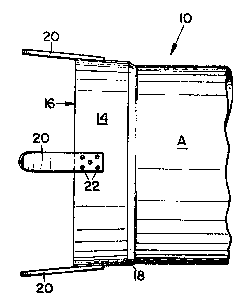
Fig. 1 is a front elevational view of a first
component of the flue gas conduit connector
of the invention;
Fig. 2 is an end elevational view as seen from the
left of Fig. l;
Fig. 3 is a front elevational view of a second
component of the flue gas conduit connector
of the invention;
Fig. 4 is an end elevational view as seen from the
left of Fig. 3;
Fig. 5 is a front elevational view showing the first
and second components in mated position
preparatory to being clamped together;
Fig. 6 is a front elevational view showing the first
and second components in clamped position; and
Fig. 7 is an enlarged, fragmentary cross-sectional view
taken on line 7-7 of Fig. 6.
DESCRIPTION OF THE PREFERRED EMBODIMENT
The flue gas conduit connector of the invention includes
a first or female component 10 ormed as an integral portion of
the end of a first metallic flue gas conduit A, as shown in
Figs. 1 and 2, and a second or male component 12 formed as an
integral portion of the end of a second flue gas conduit B,
as shown in Figs. 3 and 4.
The first and second components 10 and 12 are adapted to
be brought into mating telescopic relationship and clamped
together as shown in Figs. 5 - 7.
First component 10 includes a bell-shaped, tapered, annular
end 50int 14 which tapers inwardly from an end portion outer
face 16 and terminates at an inner shoulder 18 which merges with
first flue gas conduit A.

1322~7
A plurality of flat, finger-like locking tabs 20 extend
substantially-horizontally outwardly from outer face 16 at
spaced inter-~als around bell-shaped end joint 14.
The inner end of each tab 20 is fixed as by spot welds 22
to the outer periphery of bell-shaped end joint 14, thereby
avoiding any low alloy fasteners on the interior of the joint
and providing a corrosion resistant inner 1ue passage.
Second component 12 includes a reverse bell-shaped annular,
tapered end joint 24 which tapers outwardly from an end portion
outer face 26 and terminates at an inner shoulder 28 which merges
with second flue gas conduit B.
A locking ring 30 is loosely sleeved on second flue gas
conduit B rearwardly of shoulder 28.
A resilient gasket 32 formed from silicone rubber or the
like~ is positioned on the outer periphery of bell-shaped end
joint 24 intermediate outer face 26 and shoulder 28.
Reverse bell-shaped end joint 24 of second component 12
is of appropriate size and configuration as to be snugly
receivable in bell-shaped end joint 14 of first component 10
when the two components are brought into confronting,
face-to-face position, as shown in Fig. 5.
Further inward movement of second component 12 relative to
first component 10 will wedge gasket 32 on the outer face of
reverse bell-shaped end joint 24 against the inner face of
bell-shaped end joint 14, to create an air-tight seal between
the components.
At this time, the first and second components may be
securely clamped together by deflecting the outer ends of locking
tabs 20 down~ardly relative to shoulder 28 of second component 12,
sliding locking ring 30 over the tab ends, and then bending the
tab ends over the locking ring as shown in Figs. 6 and 7.

~322~17
The design is such that as tabs 20 are bent over sliding
ring 30, the ring is pulled onto shoulder 28, drawing the
bell-shapecl joints 14 and 24 together tightly into the
resilient gasket ~2.
It will be apparent that the flue gas conduit connector
hereof creates a corrosion resistant inner 1ue passage
uncorrupted by low alloy fasteners of any kind, in a system
which will contain low pressure venting of mildly corrosive
exhaust gases through the use of a taper fit secured by the
locking tabs and a sliding ring.
Herein, all components of the joint configuration are
external to the inner flue of the system allowing inspection
at all times. The locking tabs are welded to the outside of
the belled end so that the spot welds are outside of the
flue path.
The end joint is designed so that as the locking tabs
are bent over the sliding ring the ring is pulled onto the
expanded bead drawing the taper joints together tightly
and securely into the bead of silicone based gasket material,
while preventing the ring from slipping to the next section.
- 4 -

Dessin représentatif
Une figure unique qui représente un dessin illustrant l'invention.
États administratifs

2024-08-01 : Dans le cadre de la transition vers les Brevets de nouvelle génération (BNG), la base de données sur les brevets canadiens (BDBC) contient désormais un Historique d'événement plus détaillé, qui reproduit le Journal des événements de notre nouvelle solution interne.

Veuillez noter que les événements débutant par « Inactive : » se réfèrent à des événements qui ne sont plus utilisés dans notre nouvelle solution interne.

Pour une meilleure compréhension de l'état de la demande ou brevet qui figure sur cette page, la rubrique Mise en garde , et les descriptions de Brevet , Historique d'événement , Taxes périodiques et Historique des paiements devraient être consultées.

Historique d'événement

Description Date
Inactive : Regroupement d'agents 2013-10-10
Inactive : Périmé (brevet sous l'ancienne loi) date de péremption possible la plus tardive 2010-09-07
Lettre envoyée 2009-01-21
Inactive : Correspondance - Transfert 2009-01-15
Lettre envoyée 2007-08-08
Lettre envoyée 2007-07-12
Inactive : CIB de MCD 2006-03-11
Accordé par délivrance 1993-09-07

Historique d'abandonnement

Il n'y a pas d'historique d'abandonnement

Titulaires au dossier

Les titulaires actuels et antérieures au dossier sont affichés en ordre alphabétique.

Titulaires actuels au dossier
SELKIRK CORPORATION
Titulaires antérieures au dossier
LLOYD C. GREEN
Les propriétaires antérieurs qui ne figurent pas dans la liste des « Propriétaires au dossier » apparaîtront dans d'autres documents au dossier.
Documents

Pour visionner les fichiers sélectionnés, entrer le code reCAPTCHA :


Pour visualiser une image, cliquer sur un lien dans la colonne description du document. Pour télécharger l'image (les images), cliquer l'une ou plusieurs cases à cocher dans la première colonne et ensuite cliquer sur le bouton "Télécharger sélection en format PDF (archive Zip)" ou le bouton "Télécharger sélection (en un fichier PDF fusionné)".

Liste des documents de brevet publiés et non publiés sur la BDBC .

Si vous avez des difficultés à accéder au contenu, veuillez communiquer avec le Centre de services à la clientèle au 1-866-997-1936, ou envoyer un courriel au Centre de service à la clientèle de l'OPIC.


Description du
Document 
Date
(aaaa-mm-jj) 
Nombre de pages   Taille de l'image (Ko) 
Revendications 1994-03-07 2 67
Dessins 1994-03-07 2 51
Abrégé 1994-03-07 1 13
Description 1994-03-07 5 198
Dessin représentatif 2001-08-01 1 7
Courtoisie - Certificat d'enregistrement (document(s) connexe(s)) 2009-01-20 1 104
Correspondance reliée au PCT 1993-06-06 1 44
Correspondance de la poursuite 1993-01-19 2 41
Demande de l'examinateur 1992-10-19 1 52
Correspondance de la poursuite 1992-06-24 2 33
Demande de l'examinateur 1992-05-28 1 55
Correspondance de la poursuite 1989-10-30 2 45
Taxes 2000-08-20 1 56
Taxes 1998-08-24 1 56
Taxes 2001-07-30 1 61
Taxes 2002-08-15 1 56
Taxes 1997-09-01 1 58
Taxes 1999-08-22 1 56
Correspondance 2007-07-11 1 13
Correspondance 2007-08-07 1 12
Correspondance 2007-07-23 1 23
Correspondance 2008-09-10 1 25
Taxes 1996-08-26 1 55
Taxes 1995-08-03 1 51