Sélection de la langue

Search

Sommaire du brevet 1322821 

Énoncé de désistement de responsabilité concernant l'information provenant de tiers

Une partie des informations de ce site Web a été fournie par des sources externes. Le gouvernement du Canada n'assume aucune responsabilité concernant la précision, l'actualité ou la fiabilité des informations fournies par les sources externes. Les utilisateurs qui désirent employer cette information devraient consulter directement la source des informations. Le contenu fourni par les sources externes n'est pas assujetti aux exigences sur les langues officielles, la protection des renseignements personnels et l'accessibilité.

Disponibilité de l'Abrégé et des Revendications

L'apparition de différences dans le texte et l'image des Revendications et de l'Abrégé dépend du moment auquel le document est publié. Les textes des Revendications et de l'Abrégé sont affichés :

  • lorsque la demande peut être examinée par le public;
  • lorsque le brevet est émis (délivrance).
(12) Brevet: (11) CA 1322821
(21) Numéro de la demande: 1322821
(54) Titre français: APPAREIL PHALANGIEN A AILETTES
(54) Titre anglais: FINNED PHALANGEAL DEVICE
Statut: Périmé et au-delà du délai pour l’annulation
Données bibliographiques
(51) Classification internationale des brevets (CIB):
  • A61F 02/54 (2006.01)
  • A61F 02/58 (2006.01)
  • A63B 31/04 (2006.01)
(72) Inventeurs :
  • GABOURIE, ROBERT (Canada)
(73) Titulaires :
  • NIAGARA PROSTHETICS & ORTHOTICS CORP.
(71) Demandeurs :
  • NIAGARA PROSTHETICS & ORTHOTICS CORP. (Canada)
(74) Agent: MITCHES & CO.
(74) Co-agent:
(45) Délivré: 1993-10-12
(22) Date de dépôt: 1989-02-21
Licence disponible: Oui
Cédé au domaine public: S.O.
(25) Langue des documents déposés: Anglais

Traité de coopération en matière de brevets (PCT): Non

(30) Données de priorité de la demande: S.O.

Abrégés

Abrégé anglais


- 7 -
TITLE
FINNED PHALANGEAL DEVICE
APPLICANT
NIAGARA PROSTHETICS AND ORTHOTICS CORP.
INVENTOR
Robert GABOURIE C. P.
ABSTRACT
A finned phalangeal device includes a plurality of
spacially disposed, phalanges. On each phalange, a
longitudinal flexible fin element is attached on the back side
while allowing the longitudinal margins of each flexible film
element to extend normally toward a like element on an
adjacent phalange. When the device is moved in one direction
through a fluid the flexible fin elements feather against the
phalange and allow the fluid to pass between adjacent
phalanges with relatively little resistance. When the device
is moved in the opposite direction the flexible fin elements
open to adjacently overlay each other and hence to provide a
fluid seal inhibiting fluid flow between adjacent phalanges.
In one embodiment the phalanges are integral members of a
glove and specifically are finger encircling elements thereof
while in another embodiment each phalange is a rigid
prosthesis element simulating those fingers.

Revendications

Note : Les revendications sont présentées dans la langue officielle dans laquelle elles ont été soumises.


The embodiments of the invention in which an exclusive
property or privilege is claimed are defined as follows:
1. A finned phalangeal device comprising;
(a) a plurality of spacially disposed phalanges that
at one end merge into a body portion;
(b) attachment means defined by the body portion for
attachment of the body portion to a protruding section of a
human limb whereby to secure the device thereto; and,
(c) a plurality of longitudinal flexible fin elements
overlaying each phalange and having protruding longitudinal
margins, the margins protruding beyond each phalange and
adapted, to feather against the phalange when the device is
moved through a liquid in one direction and hence to allow
passage of the liquid between adjacent phalanges and when the
device is moved through the liquid in the opposite direction
to move into an extended and protruding position to make
overlaying contact with the margin of an adjacent element so
as to form a fluid barrier or seal between adjacent
phalange.
2. The device claimed in claim 1 wherein each flexible fin
element is elastameric.
3. The device claimed in claim 2 wherein the body portion
is a tubular portion that is adapted to overlay the palm and
the back of the hand, and each phalange is a tubular finger
engaging element.
4. The device claimed in claim 1 or 2 wherein each
phalange is a rigid longitudinal element that at one end
extends into a rigid formed body portion, the body portion
carrying said attachment means (b).
5. The device claimed in claim 1 or 2 wherein each
phalange is a rigid longitudinal element that at one end
extends into a rigid formed body portion, the body portion
carrying said attachment means (b) wherein the attachment

means is a threaded stud.
6. The device as claimed in claim 3 wherein the attachment
means is a wrist engaging cuff.

Description

Note : Les descriptions sont présentées dans la langue officielle dans laquelle elles ont été soumises.

` 11 3~2~1
This invention relates to a prosthesis and particularly
one which is adapted to be afixed to the end of one of the
upper limbs such as, over the hand or as a replacement for a
hand, or ~o the wrist.
Those who have lost a Einger or Eingers, or a hand, or
have had an upper limb severed at or below the elbow have
dLE~Lculty ~n swimming as there are insufficient or no fingers
avallable to form a "web" and tlence to provide the mechanical
means for an efficient power stroke of the arm.
Swimming is an exerclse that beneEits ones health and is
particularly helpful to handlcapped persons and should be
encouraged.
I have conceived of a fixture, which in one embodiment
is in the Eorm of a glove whose finger encircling elements
have flexible lateral fin-like projections which when the palm
oE a hand is moved in a power stroke direction, against the
water, the projections open to mate against adjacent
projections and hence provide a web like seal to water thus
converting the arm stroke into a power stroke for the swimmer.
In an alternative embodiment, the projections are
affixed to each rigid phalange oE a prosthesis which is
structured in the Eorm of a hand; the prosthesis having means
for attaching the same to the wrist or upper arm.
In the power stroke, both embodiments operate -the same~
In the recovery stroke, the projections feather against the
finger encircling elements oE the glove or feather against the
phalange of the prosthesis so as to allow easy movement
through the water with little resistance.
In sum~ary therefore, -the invention has as an objectl a
finned phalangeal deYice includes a plurality of spacially
disposed, phalanges. On each phalange, a longitudinal
flexible fin element is attached on the ~ack side while
allowing the longitudinal margins of each flexible film
element -to extend normally toward a like element on an
adjacent phalange. When the device is moved in one direction
through a fluid the flexible ~in elements feather against the ~-
~e" !
~' ' '' ' ' ' ' " '

~2232~1
-- 2
phalange and allow the f:luid to pass between adjacent
phalanges with relatively little resistance. When the device
is moved ln the opposite direction the flexible fin elements
open to adj~cently overlay each other and hence to provide a
Eluid seal inhibiting fluid elow between adjacent phalanges.
In one embodiment the phalanges are integral me~bers of a
glove and speciEica~l~ are Einger ~ncircling elements thereof
whlle in another embodimellt each phalange is a ~igid
prosthesis elemellt simulating those fingers.
The invention thereEore contemplates a finned phalangeal
device comprising:
(a) a plurality of spacially disposed phalanges that at
one end merge into a body portion;
(b) attachment means defined by the body portion for
attachment of the body portion to a protruding section
of a human limb whereby to secure the device thereto;
and,
(c) a plurality of longitudinal flexible fin elements
overlaying each phalange and having protruding
longitudinal margins, the margins protruding beyond
each phalange and adapted, to Eeather against the
phalange when the device is moved through a liquid in
one direction and hence to allow passage of the liquid
between adjacent phalanges and when the device is moved
through the liquid in -the opposite direction -to move
into an extended and protruding position to make over-
laying contact with the margin of an adjacent element
so as to form a fluid barrier or seal between adjacent
phalanges.
Additionally, the body portion may be a tubular overlay
of the palm and back of the hand and each phalange an integral
tubular finger engaging element so as to form a glove. In
this embodiment, the glove can be a ~abric or an elastomeric.
The flexible fin elements can also be elastomeric.
In another embodiment, each phalangeal is a rigid
longitudinal element that at one end extends into a rigid form
,
. .

. --
:~3~82~
-- 3
body portion resembling that of a palm and having means for
a-ttachmen-t to a severed upper limb.
The embodimen-ts o:E the invention will now be described by
way oE example and reEerence the accompany.ing drawings in
which:
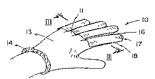
Figure I illustrates a glove emplo~:ing the Ein-like
pro~ection~ on the flngers.
E`igure 2 is a perspective view Oe a prosthesis employing
simllar fins~
Figure 3 i9 sectional view along III-III of figure 1.
Figure 4 is a sectional view along IV-IV of ~igure 2.
Figure 5 illustrates the insertion o.E the pros-thesis of
Eigure 2 into the stump of a :Eorearm.
Figure 6 is a perspective of a swimmer employing the
prosthesis of figures 1 or 2.
ReEerring to Eigure 1, a glove 10 is generally shown
having finger encircling elements 11 integral to both the palm
. side 12 and the back of the hand side 13; the palm and back of
i the hand sides re~pectively are interjoined and terminate at a
; 20 wrist-like cuff or wrist engagement means 14.
Each oE the :Einger encircling elemen-ts 11 has along the
upper back margin thereof and welded thereto at 16 a
longitudinal sheek or fin member 17 with opposite flexible
lateral margins 18.
Referr.ing to figures 3A and 3B, when the glove is moved
backward.s, during ~he recovery stroke in the direction of
arrows 20, through water 22, the water travels in the
direction of arrows 23 between the finger encircling elements
11 and causes each of the flexible fins 17 to feather into the
position indicated in f.igure 3A.
Referring to figure 3B which is illustrative of the
power stroke, when the glove 10, is moved by the hand, in
direction 25, as during swimming and hence against the water
22, the water follows in the paths of arrows 26, and 27 and
urges the fins 17, move from the Eeathered position shown in
figure 3A to that of figure 3B so that the distal margins of
.
, ~ ..
. ', ~
.
. ~ . , :
: ~ :

.
132282 L
adjacent fins overlap as shown. Th.is provides resistance to
the water and a power stroke can be initiated without the
fingers being put together in a juxtaposed manner. Those who
have arthritis in the hand will find such glove of use in
swimm:ing.
Re.EerrLng now to :E.igures 2, 4~ and 4~ a prosthesis 10'
is ge~nerally shown having .Eins 17' installed along phalanges
11l, the pha.Langes merging into a base or palm piece l2' and
terminating with a prokruding stud 15 which, as seen :in .Eigure
5 is adapted, to he screwed into a .Eorearm stump 30 tha-t has a
forward receiver, not shown, adapted to matingly engage with
the threaded s-tud 15.
In a similar fashion and referring to figures 4A and 4B,
dueing the forward recovery stroke or movement of the
prosthesis 10' as in figure 4A the fins 17 are feathered and
water teavels in the direction of arrow 23'~ During the power
stroke, adjacent fins move -to overlap along there adjacent
margins overlap, as shown in :Eigure 4A, and the power stroke
is initiated in the direction o.E arrow 25'.

Dessin représentatif
Une figure unique qui représente un dessin illustrant l'invention.
États administratifs

2024-08-01 : Dans le cadre de la transition vers les Brevets de nouvelle génération (BNG), la base de données sur les brevets canadiens (BDBC) contient désormais un Historique d'événement plus détaillé, qui reproduit le Journal des événements de notre nouvelle solution interne.

Veuillez noter que les événements débutant par « Inactive : » se réfèrent à des événements qui ne sont plus utilisés dans notre nouvelle solution interne.

Pour une meilleure compréhension de l'état de la demande ou brevet qui figure sur cette page, la rubrique Mise en garde , et les descriptions de Brevet , Historique d'événement , Taxes périodiques et Historique des paiements devraient être consultées.

Historique d'événement

Description Date
Inactive : CIB de MCD 2006-03-11
Inactive : Demande ad hoc documentée 1996-10-12
Le délai pour l'annulation est expiré 1996-04-14
Lettre envoyée 1995-10-12
Accordé par délivrance 1993-10-12

Historique d'abandonnement

Il n'y a pas d'historique d'abandonnement

Titulaires au dossier

Les titulaires actuels et antérieures au dossier sont affichés en ordre alphabétique.

Titulaires actuels au dossier
NIAGARA PROSTHETICS & ORTHOTICS CORP.
Titulaires antérieures au dossier
ROBERT GABOURIE
Les propriétaires antérieurs qui ne figurent pas dans la liste des « Propriétaires au dossier » apparaîtront dans d'autres documents au dossier.
Documents

Pour visionner les fichiers sélectionnés, entrer le code reCAPTCHA :


Pour visualiser une image, cliquer sur un lien dans la colonne description du document (Temporairement non-disponible). Pour télécharger l'image (les images), cliquer l'une ou plusieurs cases à cocher dans la première colonne et ensuite cliquer sur le bouton "Télécharger sélection en format PDF (archive Zip)" ou le bouton "Télécharger sélection (en un fichier PDF fusionné)".

Liste des documents de brevet publiés et non publiés sur la BDBC .

Si vous avez des difficultés à accéder au contenu, veuillez communiquer avec le Centre de services à la clientèle au 1-866-997-1936, ou envoyer un courriel au Centre de service à la clientèle de l'OPIC.

({010=Tous les documents, 020=Au moment du dépôt, 030=Au moment de la mise à la disponibilité du public, 040=À la délivrance, 050=Examen, 060=Correspondance reçue, 070=Divers, 080=Correspondance envoyée, 090=Paiement})


Description du
Document 
Date
(aaaa-mm-jj) 
Nombre de pages   Taille de l'image (Ko) 
Revendications 1994-03-03 2 52
Dessins 1994-03-03 2 46
Abrégé 1994-03-03 1 30
Description 1994-03-03 4 163
Dessin représentatif 2000-08-16 1 6
Correspondance reliée au PCT 1993-07-01 1 31
Correspondance de la poursuite 1992-11-08 1 35
Correspondance de la poursuite 1989-10-01 1 39
Correspondance de la poursuite 1989-09-05 2 41
Demande de l'examinateur 1992-11-01 1 63