Sélection de la langue

Search

Sommaire du brevet 1323898 

Énoncé de désistement de responsabilité concernant l'information provenant de tiers

Une partie des informations de ce site Web a été fournie par des sources externes. Le gouvernement du Canada n'assume aucune responsabilité concernant la précision, l'actualité ou la fiabilité des informations fournies par les sources externes. Les utilisateurs qui désirent employer cette information devraient consulter directement la source des informations. Le contenu fourni par les sources externes n'est pas assujetti aux exigences sur les langues officielles, la protection des renseignements personnels et l'accessibilité.

Disponibilité de l'Abrégé et des Revendications

L'apparition de différences dans le texte et l'image des Revendications et de l'Abrégé dépend du moment auquel le document est publié. Les textes des Revendications et de l'Abrégé sont affichés :

  • lorsque la demande peut être examinée par le public;
  • lorsque le brevet est émis (délivrance).
(12) Brevet: (11) CA 1323898
(21) Numéro de la demande: 1323898
(54) Titre français: CONFIGURATION DE TRESSE DE DISJONCTEUR EN BOITIER MOULE
(54) Titre anglais: MOLDED CASE CIRCUIT BREAKER LINE STRAP CONFIGURATION
Statut: Périmé et au-delà du délai pour l’annulation
Données bibliographiques
(51) Classification internationale des brevets (CIB):
  • H01H 33/02 (2006.01)
  • H01H 09/34 (2006.01)
  • H01H 11/06 (2006.01)
(72) Inventeurs :
  • ARNOLD, DAVID (Etats-Unis d'Amérique)
  • KOWALCZYK, KAREN BLOOMQUIST (Etats-Unis d'Amérique)
(73) Titulaires :
  • GENERAL ELECTRIC COMPANY
(71) Demandeurs :
  • GENERAL ELECTRIC COMPANY (Etats-Unis d'Amérique)
(74) Agent: RAYMOND A. ECKERSLEYECKERSLEY, RAYMOND A.
(74) Co-agent:
(45) Délivré: 1993-11-02
(22) Date de dépôt: 1989-09-21
Licence disponible: S.O.
Cédé au domaine public: S.O.
(25) Langue des documents déposés: Anglais

Traité de coopération en matière de brevets (PCT): Non

(30) Données de priorité de la demande:
Numéro de la demande Pays / territoire Date
292,717 (Etats-Unis d'Amérique) 1989-01-03

Abrégés

Abrégé anglais


MOLDED CASE CIRCUIT BREAKER
LINE STRAP CONFIGURATION
ABSTRACT OF THE DISCLOSURE
A molded case circuit breaker enclosure
cooperates with the current-limiting line strap to
prevent the egress of ionized gases. The gases are
generated by a high temperature arc which occurs when
the contacts are separated under short circuit
conditions.

Revendications

Note : Les revendications sont présentées dans la langue officielle dans laquelle elles ont été soumises.


- 5 -
The embodiments of the invention in which an
exclusive property or privilege is claimed are defined
as follows:
1. A circuit breaker enclosure comprising:
a molded plastic cover;
a molded plastic case including a plurality of
line lug compartments at one end and a corresponding
plurality of load lug compartments at an opposite end;
a plurality of arc chambers abutting said line
lug compartments and separated therefrom by an
upstanding compartment wall integrally-formed within
said case;
a plurality of line straps within said arc
chambers and extending within said line lug
compartments through a corresponding plurality of
openings through a bottom of said compartment wall,
each of said line straps including means formed on one
end cooperating with means formed on opposing edges of
said openings to thereby prevent the egress of arc
gases from said case during circuit interruption.
2. The circuit breaker enclosure of Claim 1
including a plurality of pedestals integrally-formed on
a bottom surface of said case, said pedestals receiving
corresponding slots formed through said line straps.
3. The circuit breaker enclosure of Claim 1
wherein each of said line straps comprise a U-shaped
configuration including a planar top and bottom part,
said line strap means comprising ridges formed on
parallel edges of said bottom part.
4. The circuit breaker enclosure of Claim 1
wherein said means formed on said openings comprise
wedges integrally-formed within said case.
5. The circuit breaker enclosure of Claim 3
wherein said parallel edges taper towards each other.
6. The circuit breaker enclosure of Claim 2

- 6 -
wherein said pedestals include a forward surface
inclining towards said openings to facilitate receiving
said line strap slot.
7. The circuit breaker enclosure of Claim 1
including projections integrally-formed subjacent said
openings to cooperate with said line strap bottom part
to further prevent egress of said arc gases.
8. The circuit breaker enclosure of Claim 1
including a corresponding plurality of load strap
compartments at opposite ends of said case and a
corresponding plurality of load straps within said load
strap compartments.
9. The circuit breaker enclosure of Claim 4
including a corresponding plurality of protuberances
formed on said wedges, said protuberances providing
stops to said line strap edges when said line straps
are inserted through said compartment openings.

Description

Note : Les descriptions sont présentées dans la langue officielle dans laquelle elles ont été soumises.

L ~ ~ 3 i '~ ~
lPR-06644
MOLDED CA8E 8TRAP CIRCUIT B~EARER
LINB 8TRAP CONFIGUR~TION
BACRG~OIIND OF T}~E~ INVENTION
Current-limiting circuit breakers are
currently designed to interrupt a fault condition in
the early stages of the let-through current waveform to
substantially reduce the intensity of the arc that
occurs between the contacts during the rapid separation
process. To promote the electrodynamic repulsion that
occurs between the fixed line strap that supports the
line contact and the movable contact arm that supports
the movable contact, the line strap i5 provided with a
"reverse loop~ onfiguration. One example of an
efficient current-limiting circuit breaker employing
such a reverse loop line strap is found within U.S.
Patent 4,679,016.
In order to rapidly de-ionize and thermally
quench the arc, an arc chute configuration is employed
having good mechanical strength and further having the
ability to generate electronegative gases which both
de-ionize as well as thermally cool the arc. One
example of an arc chute composition having specific gas
evolving properties is described within U.S. Patent
4,748,301.
To prevent the egress of such ionized gases
from the circuit breaker enclosure, a sealant material
is generally applied to the outside of the circuit
breaker enclosure where the line straps exit to join
the line strap connecting lugs. With the advent of
~`

4lPR-06644
- 2 -
robotic assembly of the circuit breaker components, it
is essential to eliminate as many production steps as
possible in order not to interfere with the efficiency
of the components assembly process.
One purpose of the instant invention is to
provide means for automatically sealing the circuit
breaker enclosure from the arc gases generated during
circuit interruption without requiring any sealant
material on the exterior of the circuit breaker
enclosure.
8UMMARY OF TRE INVENTION
The invention comprises a reverse loop line
conductor that is configured to cooperate with
complementary extensions formed on the interior of a
circuit breaker molded plastic case. The bottom
interior of the case is configured to accept the
reverse loop line strap in a press-fit configuration.
BRIFF DE8CRIPTION OF TRE DRAWING~
Figure 1 is a plan view of a molded case
circuit breaker with the cover partially removed to
show the line straps according to the invention:
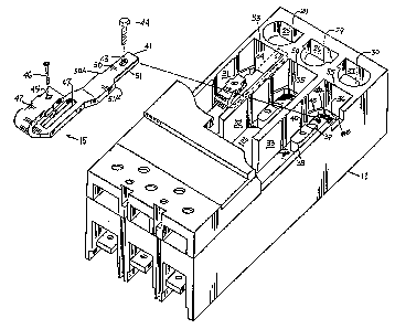
Figure 2 is a top perspective view of the
circuit breaker of Figure l with the cover partially
removed and the line straps in isometric projection;
Figure 3A and 3B are side views in partial
section depicting the assembly of the line straps shown
in Figures 1 and 2;
Figure 4 is a cut-away plan view of the
circuit breaker case depicted in the preceding
drawings; and
Figure 5 is a top perspective view of the
circuit breaker of Figure 1 depicting an alternative
embodiment of the line strap of the invention.
DE~CRIPTION OF TRE PREFERRED ENBODINENT
A current-limiting circuit breaker 10 is

~ .3 ~ 3
4lPR-06644
-- 3 --
depicted in Figure 1 and includes a molded plastic case
11 to which a molded plastic cover 12 is secured. The
cover includes an ON-OFF operating handle 13 that exits
through the cover aperture 14. Electrical connection
with the electrical distribution power buses (not
shown) is made by means of the line straps 15-17 which
are electrically isolated from each other by means of
integrally-formed baffles 18, 19. Electrical
connection with an associated load is made by means of
the load straps ~0-22 which are similarly isolated from
each other by means of integrally-formed baffles 23,
24.
The line straps, such as depicted at 15 in
Figure 2 are each assembled within corresponding arc
chambers 31-33 such that the forward part 41 through
slots 34-36 to within the line lug compartments 25-27.
Walls 53-55 are integrally-formed within the circuit
breaker case and separate the arc chambers from the
line lug compartments. The line lug compartments are
externally accessible through the openings 28-30 formed
in the end of the case. In assembling the line strap
15 within the arc chamber 33, for example, the forward
part 41 is inserted within slot 36 and extended through
the slot until the ridges 50A, 51A formed on the
respective edges 50, 51 strike against the
protuberances 49A, 49B in the arc chamber 33 that are
formed at the juncture between wedge-shaped extensions
48 and the corresponding slot 36. The line strap is
then rotated down until the slot 47 formed in the line
strap encompasses the pedestal 38 integrally-formed in
the bottom 37 of the case and which includes a forward
sloped surface 39 to guide and accommodate the line
strap. An opening 40 receives a retainer screw 46 for
fastening the line strap to the case by means of the
thru-hole 45 formed in the reverse loop part 42 of the
. .
,, ` ~ ' .

L~ "
41PR-06644
- 4 -
line strap. When the line strap is fastened to the
case, the busbar connector 44 is threadingly attached
by means of the threaded opening 43 formed in the
forward part 41 which extends within the line lug
compartment 27. The case 11 is depicted in Figure 4 to
shown the protuberances 49A, 49B on opposite sides of
the slot 36 and formed on opposing wedge-shaped
extensions 48A, 48B ahead of the pedestal 38.
The assembly of the line strap 15 is best seen
by now referring to Figures 3A, 3B wherein the forward
part 41 is shown extending through slot 36 with the
ridge 50A of the tapered edge 50 stopped against the
protuberance 49A formed on the wedge-shaped extension
48A on one side of the slot 36. The ridge 51A on the
opposing tapered edge 51 also stops against a similar
protuberance 49B shown earlier in Figure 4. A
projection 52 is formed on the bottom of the case 11 to
provide for a press-fit connection between the line
strap 15 and the top and bottom edges of the slot 36
when the line strap is next rotated in the downward
direction to capture the pedestal 38 within the slot
47. As described earlier, the forward sloped surface
39 guides the line strap slot over the pedestal until
the line strap becomes completely supported by the
bottom of the case as best seen in Figure 3B.
In some circuit breakers having higher ampere
ratings, an elastomeric ~-ring or washer 56 is first
arranged over the forward part 41 of the line strap 15,
shown in Figure 5, until the washer becomes stopped by
the ridges 50A, 51A formed at the ends of the tapered
edges 50, 51. When the line strap is later inserted
within the corresponding slot 36, the washer 56
completely seals the interstices that may occur when
the line strap forward part 41 is completely inserted
through slot 36.
, ~ ' .

Dessin représentatif
Une figure unique qui représente un dessin illustrant l'invention.
États administratifs

2024-08-01 : Dans le cadre de la transition vers les Brevets de nouvelle génération (BNG), la base de données sur les brevets canadiens (BDBC) contient désormais un Historique d'événement plus détaillé, qui reproduit le Journal des événements de notre nouvelle solution interne.

Veuillez noter que les événements débutant par « Inactive : » se réfèrent à des événements qui ne sont plus utilisés dans notre nouvelle solution interne.

Pour une meilleure compréhension de l'état de la demande ou brevet qui figure sur cette page, la rubrique Mise en garde , et les descriptions de Brevet , Historique d'événement , Taxes périodiques et Historique des paiements devraient être consultées.

Historique d'événement

Description Date
Inactive : CIB de MCD 2006-03-11
Le délai pour l'annulation est expiré 1997-11-03
Lettre envoyée 1996-11-04
Accordé par délivrance 1993-11-02

Historique d'abandonnement

Il n'y a pas d'historique d'abandonnement

Titulaires au dossier

Les titulaires actuels et antérieures au dossier sont affichés en ordre alphabétique.

Titulaires actuels au dossier
GENERAL ELECTRIC COMPANY
Titulaires antérieures au dossier
DAVID ARNOLD
KAREN BLOOMQUIST KOWALCZYK
Les propriétaires antérieurs qui ne figurent pas dans la liste des « Propriétaires au dossier » apparaîtront dans d'autres documents au dossier.
Documents

Pour visionner les fichiers sélectionnés, entrer le code reCAPTCHA :


Pour visualiser une image, cliquer sur un lien dans la colonne description du document (Temporairement non-disponible). Pour télécharger l'image (les images), cliquer l'une ou plusieurs cases à cocher dans la première colonne et ensuite cliquer sur le bouton "Télécharger sélection en format PDF (archive Zip)" ou le bouton "Télécharger sélection (en un fichier PDF fusionné)".

Liste des documents de brevet publiés et non publiés sur la BDBC .

Si vous avez des difficultés à accéder au contenu, veuillez communiquer avec le Centre de services à la clientèle au 1-866-997-1936, ou envoyer un courriel au Centre de service à la clientèle de l'OPIC.

({010=Tous les documents, 020=Au moment du dépôt, 030=Au moment de la mise à la disponibilité du public, 040=À la délivrance, 050=Examen, 060=Correspondance reçue, 070=Divers, 080=Correspondance envoyée, 090=Paiement})


Description du
Document 
Date
(aaaa-mm-jj) 
Nombre de pages   Taille de l'image (Ko) 
Abrégé 1994-07-15 1 10
Dessins 1994-07-15 4 99
Revendications 1994-07-15 2 57
Description 1994-07-15 4 147
Dessin représentatif 2001-11-26 1 19
Taxes 1995-10-11 1 56
Demande de l'examinateur 1992-07-22 1 61
Correspondance de la poursuite 1992-09-30 2 53
Correspondance reliée au PCT 1993-07-28 1 33