Note : Les descriptions sont présentées dans la langue officielle dans laquelle elles ont été soumises.
2 ~
1 The invention generally relates to an ejector, and
2 in particular the invention relates to a steam chest
3 allowing for an easily replaceable nozzle subassembly.
Ba~grou~d of the Invontio~
7 The prior art ejectors include a steam chest having
8 an axis and a steam chest cavity, a suct:ion chamber
9 coaxial with the steam chest and having a suction chamber
cavity, a di~user coaxial with steam chest and suction
11 chamber and havin~ an elongate passage, a nozzle
12 subassembly extending frQm the steam chest through the
13 suction chamber cavity, and a construction joint disposed
14 between the steam chest and suction chamber for
disassembly and reassembly thereof for replacing,
16 cleaning or repairing the nozzle subassembly.
17 One problem with the prior art ejector assembly is
18 that the time to disassemble and reassemble the steam
19 chest and the nozzle subassembly into the suction chamber
is relatively long causing extensive down time o~ the
21 associated processing equipment.
22
23 ~ummary o~ ~he InYention
24
According to the present invention, a modified
26 ejector is provided which is easily disassembled. This
27 ejector includes a steam chest having an axis and having
28 a steam chest cavity, a suction chamber coaxial with the
29 steam chest and having a suction chamber cavity, a
di~fuser coaxial with the steam chest and the suction
31 chamber and having an elongate passage, a nozzle
32 subassembly extending through the steam chest cavity and
33 the suction chamber cavity, said steam chest having an
34 outside end wall and a peripheral wall and an in~ide end
wall
.~
~, ,,~, ,.
~ X VL5:in
, .~
.
.,
.. . ~ . , .
2 1~2~
1 with the nozzle subassembly, the opening having a removable
2 cap for removing and replacing the nozzle subassembly
3 therethrough. The nozzle unit has an enlarged portion having
4 a bearing surface for engaginy a bearing surface in the steam
- 5 chest, an externally threaded portion for receival in an
6 internally threaded hole in the steam chest, an elongate
7 passage interconnecting the steam chest cavity with the
8 suction chamber cavity, an end portion with an openi~g, and
g a nozzle insert received in the end portion opening. The
nozzle insert has a passage portion having an inlet portion,
~ 11 a necked down portion and an outlet portion. The steam chest
- 12 inside wall and an adjacent end wall of the suction chamber
: .
13 have a plurality of matching holes of the same angular
14 spacing and overall diameter for a plurality of bolts. The
diffuser and the suction chamber have bare adjacent
16 respective wall portions having a plurality of matching holes
17 of the same angular spacing and overall diameter for a
18 plurality of bolts for facilitating joining of the steam
19 chest inlet opening and suction chamber inlet opening to
outside piping connections.
21 By using the end wall opening and removable cap
22 disposed coaxially with the nozzle subassembly, the time of
23 replacing the nozzle subassembly is minimized.
,"~
24 The foregoing and other objects, features and
, 25 advantages will be apparent from the following description
26 of preferred embodiments of the invention as illustrated in
27 the accompanying drawings.
. ~
~ .
-`~ 28 Brief De~cription of the ~rawing~
,
29 Figure 1 is a section view of an ejector assembly
;~ 30 according to the invention;
~ 31 Figure 2 is a section view of a second embodiment of
: .~
~i~? 32 the ejector with a steam chest portion; and
., ~
~ . . .
LCD:vs
':~
j; ,
::~i B
..
.- .
,
;....................................... , ~,
. ; . .
.....
.
,
. .,
: ` :
` 2a 132~41~
1 Figure 3 is a section view as taken along the line
2 3-3 of Figure 2;
3 Figure 4 is a section view of a third embodiment of
4 the steam chest portion of the ejector; and
~ 5 Figure 5 is a section view of a fourth embod.iment of
: 6 the steam chest portion of the ejector.
7 De~cription of the Preferred Embodime~ts
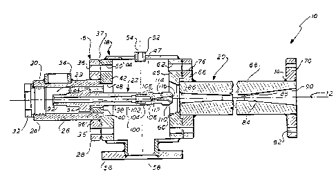
. 8 As shown in Figure 1, a steam ejector 10 is
9 provided. The ejector 10 has an elongate axis 12 and is a
~ 10 welded subassembly having a typical weld 14. The ejector 10
: 11 includes a steam chest 16, which has a round profile in cross
12 section, and includes a su¢tion chamber 18, which has a
13 cylindrical profile in cross section. The ejector 10 also
, 14 includes a diffuser 20, which has a cylindrical profile in
:;; 15 cross section, and includes a nozzle subassembly 22, which
~ 16 also has a cylindrical profile in cross section and which is
., 17 disposed inside the steam chest 16 and suction chamber 18,
:l 18 and which is supported by the steam chest 16.
.
,:
: .
,:
:
i,.. .
, .
,
, .,
,.',,j~
,:..
',
:.~
.i,i LCD: vs
.~. .
; iB
1.,
:'.,, '. ' ~ ~
:,'',:' ' : . ~
::
. ' :, , , , ` .
'. r
. ~, .
` ~32~
1 The steam chest 16 has a left outside end wall 24, a
2 peripheral wall 26 and a right inside end wall 28 forming
3 a cavity 29. The left end wall 24 has an internally
4 threaded hole 30 with an externally threaded cap or plug
, 5 32.
6 The peripheral wall 26 has a threaded pipe
7 connection 34 for use as a fluid inlet or an air inlet or
8 a steam inlet. Right end wall 28 has a plurality of
9 connector holes 36 for bolts ~not shown) for forming an
assembly joint 37. The right end wall 28 has an inner
11 wall portion 38, which has an internally threaded hole
12 40, that is coaxial with nozzle subassembly 22.
13 The suction chamber 18 has a left end wall 42, a
14 peripheral wall 44, and a right end wall 46 forming a
cavity 47. Walls 42, 44, 46 have a cylindrical profile
, 16 in cross section.
17 The left end wall 42 has an inner hole 48, which is
, 18 coaxial with hole 40, and with nozzle subassembly 22.
"l 19 Left end wall 42 has a plurality of connector holes 50
which are aligned with respective holes 36.
21 The peripheral wall 44 has a pipe portion 52, which
~ 22 has an internally threaded hole 54 for a conventional
`~ 23 vacuum gage (not shown). Peripheral wall 44 has a flange
~J~ 24 connection 56, which has an inlet opening 58 for
connection to a conventional condenser (not shown).
26 Right end wall 46 has an inner hole 60, which has an
j 27 inner diameter that decreases in size from left to right.
28 Hole 60 is coaxial with hole 48. The right end wall 46
29 also has a plurality of connector holes 62 for bolts ~not
shown).
z, 31 The right end wall 28 of the steam chest 16 also has
32 a bearing surface or machined surface 64 on its axially
33 inner side. Surface 64 is a stop surface for threading
~q 34 nozzle assembly 22 into place, as explained hereafter,
"''J 35 after inserting nozzle assembly 22 through hole 30.
!;~ 36 Diffuser 20 has a left end wall 66, a peripheral
~ 37 wall 68, and a right end wall 70. The left end wall 66
~,
i, VLS:in
:
, :
.
. ~ ~
,., :~
4 ~32~
1 has respectively aligned with holes 62. Peripheral wall
2 68 is connected to right end wall 70 which has a
3 plurality of connector holes 82. Diffuser 20 has an
4 elongate passage 84, which has a selective elongate inner
profile, and which has an inlet portion 86 and a necked
6 down portion 88 and a discharge portion 90.
7 The nozzle subassembly 22 has a left end portion 92
8 of hexagonal profile in cross section, and an enlarged
9 portion 94, which has a kearing surface 96 that engages
bearing surface 64. The nozzle subassembly 22 has a
11 threaded portion 98, which is threaded into threaded hole
12 40, and has a right end portion 100. The nozzle
13 subassembly 22 further has an elongate pas~age 102.
14 Right end portion 100 has an internally threaded
portion 104, which receives a nozzle insert 106. The
16 insert 106 has an externally threaded portion 108, which
17 is received in portion 104. The insert 106 has a passage
18 110, which has an inlet portion 112~ a necked down
19 portion 114 and an outlet portion 116.
With the construction of the ejector 10, end cap 32
21 can be removed in order to remove nozzle subassembly 22
22 through end hole 30. Thus, the time to replace nozzle
23 subassembly 22 is minimized. The primary benefit of
24 ejector 10 is that it can be easily taken apart to
replace the nozzle assembly 22, which is the part that
26 has the most wear.
.,.~ ,,,
27 Following are advantages of the ejector 10:
28 Only the step of checking or removing nozzle
29 assembly 22 is required. Many additional steps to check
the prior art ejector are avoided.
31 First, disconnect of steam line is avoided.
32 Second, removal of steam pressure gage is avoided.
33 Third, removal of steam chest bolts is avoided.
34 Fourth, prying loose of steam chest is avoided.
Fifth, unscrewing extensions and removing spacers
36 are avoided.
37 Sixth, after checking the nozzle subassembly, the
VLS:in
. ', ~
~,
,, i, ~ ~ . .
... .
:. ~
~2~
1 reinstalling of a gasket between the steam chest and
2 suction chamber is a~voided.
3 Seventh, reinstalling the steam chest bolts is
4 avoided.
Eight, reinstalling the steam pressure gage is
6 avoided.
7 Ninth, reconnecting the steam lin~ is avoided.
B Other advantages of generator 10 are indicated
9 below:
Only the detail steps of unscrewing the cap 32 and
~, 11 nozzle subassembly 22 using wrenches, and later screwing
12 back the nozzle subassembly 22 and cap 32 are required.
~ 13 Figure 2 shows a second e~bodiment or ejector lOa.
1 14 Parts of ejector lOa in Figure 2, which are the same as
parts of the ejector 10 in Figure 1, have the same
! 16 numerals, but with a subscript "a" added thereto. Figure
~ 17 2 corresponds to a portion only of Figure 1.
`A' 18 The ejector lOa which has an axis 12a, includes a
19 steam chest 16a and a nozzle subassembly 22, supported
~l 20 therefrom. The steam chest 16a has a left wall 24a, a
2~ peripheral wall 26a and a right wall 28a. Left wall 24a
22 has an internally threaded end hole 30a. The peripheral
23 wall 26a has an internally threaded gage hole 144 and has
24 an internally threaded pipe connection 34a. Right wall
28a has a plurality of connector holes 36a and an inner
26 wall portion 38a, which has a threaded inner hole 40a~
~, 27 Nozzle subassembly 22a has an enlarged portion 118
28 with a bearing surface 120 which engages a surface 64a on
29 wall 38a. Nozzle subassembly 22a has an externally
threaded portion 122 and a right end portion 124. The
31 nozzle subassembly 22a also has a passage 126. The
32 passage 126 has an inlet portion 128, a necked down
33 portion 130, and an outlet portion 132.
34 The nozzle assembly 22a has a lock nut 134.
~ 35 Peripheral wall 26a has an internally threaded portion
-~3i~ 36 136; and lock nut 134 has an externally threaded porti~n
37 142, received by portion 136. The lock nut 134 has a
i
~ V~S:in
,:g
.:,.
": ;
'~r.
"'`'.' :
'''
~32~
1 passage portion 138 which is coaxial with passage 126.
2 Lock nut 134 also has two tool receiving holes 140, which3 can receive a tool wrench with a dual prong head (not
4 shown).
The noæzle assembly 22a is better able to resist
6 loosening thereof due to vibration, because lock nut 134
7 provides a locking force thereon. The nozzle assembly
8 22a is less complicated to manufacture, as it is one
9 piece; and it is more rigid, as it has a smaller length
to diameter ratio.
11 Figure 4 shows a third embodiment of a steam chest
12 16b, which has a circular profile in cross section and
13 which is a portion of an ejector. Parts of steam chest
14 16b in Figure 4, which are the same as parts of steam
chest 16 in Figure 1, have the same numerals, but with a
16 subscript "b" added thereto. Figure 4 corresponds to a
17 steam chest portion only of Figure 1.
18 Steam chest 16b, which has an axis 12b, includes a
19 left outside end wall 25b, a peripheral wall 26b and a
right inside end wall 28b. Left wall 24b has an
21 internally threaded end hole 30b. Peripheral wall 26b
r ,~,1
22 has an internally threaded gage hole 150, and has an
23 internally threaded pipe connection 34b. Right wall 28b
24 has a plurality of connector holes 36b, and has an inner
wall portion 38b, which has a threaded inner hole 40b,
26 inner wall portion 38b has an axially inner bearing
27 surface 64b for bearing against a nozzle assembly.
28 Right wall 28b has an axially inner machined surface
29 poxtion 152. Peripheral wall 26b has an axially outer
machined surface 154, which facPs surface 152. Surfaces
31 152 and 154 have an annular butt weld 156, which is
32 disposed therebet~een. Right wall 28b has an axially
33 outer surface 158 for forming part of a construction
34 joint with a left wall of an e~ector suction chamber.
Right wall 28b is a circular, one piece, machined
3~ plate for ease of manufacture thereof.
37 Figure 5 shows a fourth embodiment of a steam chest
. .--
;;i VLS:in
~"~
.'.,~',~
:
.
., ~
,
.. . .
:
- 7 ~32~
16c which has a circular profile in cross section. Parts
2 of steam chest 16c, which are the same as parts of steam
3 chest 16 in Figure 1, have the same numerals, but with a
4 subscript "c" added thereto. Figure 5 corresponds to a
steam chest portion only of Figure 1.
6 Steam chest 16c, which has an axis 12c, includes a
7 left outside end wall 24c, a peripheral wall 26c, and a
8 right inside end wall 28c. Le~t wall 24c has an
9 internally threaded end hole 30c. Peripheral wall 26c
has an internally threaded gage hole 170, and has an
11 internally threaded pipe connection 34c. Right wall 28c
12 has an inner wall portion 38c, which has a threaded inner
13 hole 40c. Inner wall portion 38c has an axially inner
14 bearing surface 64c for bearing against a nozzle
assembly.
16 Right wall 28c has an axially outer surface 172 for
17 forming part of a construction joint with a leet wall of
18 an ejector suction chamber. Right wall 28c has a
19 projecting portion 174 which has a radially outer,
externally threaded circular surface 176, for threading
21 into a radially inner internally threaded hole (not
22 shown) in a left wall of an ejector suction chamber.
23 Right wall 28c is a threaded unit ~or ease of
24 disassenbly from and reassembly to an ejector suction
chamber.
26 Although the construction as shown of each
27 embodiment has many parts welded together it should be
28 apparent that any method of assembly is suitable and the
29 sections can be constructed of single pieces rather than
the sub sections shown. Further, although the apparatus
31 has been disclosed as used with steam it c:an also be
:i
~, 32 utilized with air or any similar fluid or gas.
-.' 33 While the invention has been described in its
, ~
34 preferred embodiments, it is to be understood that the
;~j 35 words which have been used are words of description
~ 36 rather that limitation and that changes may be made
. .
'' 37 within the purview of the appended claims without
~!
,~ ,5~.
~ VLS:in
~ ,...
"
~. X
',', :
;' , ' '
'~
,
~325~1~
, 8
1 departing from the true scope and spirit of the invention
2 in its broader aspeot~.
~,
'.
;~
., .
.~ ~
: .,.
.
~;
,,~,
,,.
.
,':~
~`
~,, .
~1 ,
,~J
y
~,
..
.~
",. i,
.,,.;
, .
~ VLS:in
..~,,
;: