Sélection de la langue

Search

Sommaire du brevet 1327268 

Énoncé de désistement de responsabilité concernant l'information provenant de tiers

Une partie des informations de ce site Web a été fournie par des sources externes. Le gouvernement du Canada n'assume aucune responsabilité concernant la précision, l'actualité ou la fiabilité des informations fournies par les sources externes. Les utilisateurs qui désirent employer cette information devraient consulter directement la source des informations. Le contenu fourni par les sources externes n'est pas assujetti aux exigences sur les langues officielles, la protection des renseignements personnels et l'accessibilité.

Disponibilité de l'Abrégé et des Revendications

L'apparition de différences dans le texte et l'image des Revendications et de l'Abrégé dépend du moment auquel le document est publié. Les textes des Revendications et de l'Abrégé sont affichés :

  • lorsque la demande peut être examinée par le public;
  • lorsque le brevet est émis (délivrance).
(12) Brevet: (11) CA 1327268
(21) Numéro de la demande: 1327268
(54) Titre français: ENCEINTE D'EPREUVE AU GAZ
(54) Titre anglais: GAS SINK
Statut: Durée expirée - après l'octroi
Données bibliographiques
(51) Classification internationale des brevets (CIB):
  • C21C 07/072 (2006.01)
  • B22D 01/00 (2006.01)
  • C22B 09/05 (2006.01)
(72) Inventeurs :
  • WINKELMANN, MANFRED (Allemagne)
  • ROTHFUSS, HANS (Allemagne)
  • METZGER, HERBERT (Allemagne)
(73) Titulaires :
  • DIDIER-WERKE A.G.
(71) Demandeurs :
  • DIDIER-WERKE A.G. (Allemagne)
(74) Agent: SMART & BIGGAR LP
(74) Co-agent:
(45) Délivré: 1994-03-01
(22) Date de dépôt: 1989-01-27
Licence disponible: S.O.
Cédé au domaine public: S.O.
(25) Langue des documents déposés: Anglais

Traité de coopération en matière de brevets (PCT): Non

(30) Données de priorité de la demande:
Numéro de la demande Pays / territoire Date
P 38 02 657.0 (Allemagne) 1988-01-29

Abrégés

Abrégé anglais


ABSTRACT
The optical identifiability of the state of wear in a gas-fluxing
stone of refractory ceramic material, is improved. The
identifiability is intended to be independent of the material of
the gas-fluxing stone. To this end, a gas-permeable separator
space 3, which has different geometric forms in the direction of
wear, extends in the gas-fluxing stone. As a result, during
throughflow of gas through the separator space 3, a pattern which
differs according to the state of wear is visible on the surface
of the gas-fluxing stone.

Revendications

Note : Les revendications sont présentées dans la langue officielle dans laquelle elles ont été soumises.


THE EMBODIMENTS OF THE INVENTION IN WHICH AN EXCLUSIVE
PROPERTY OR PRIVILEGE IS CLAIMED ARE DEFINED AS FOLLOWS:
1. A gas-fluxing stone of refractory ceramic material in
which the state of wear is optically identifiable and in which
an inner body is inserted in an outer body, wherein a gas-
permeable separator space extends in the gas-fluxing stone, and
wherein the separator space has, different geometric forms in
the direction of wear, with the result that, during the flow of
gas through the separator space, different geometric patterns
corresponding to the respective state of wear are visible on the
surface of the gas-fluxing stone.
2. A gas-fluxing stone according to claim 1, wherein the
separator space extends in the form of a gap between the outer
body of fluxing-stone material and the inner body of fluxing-
stone material.
3. A gas-fluxing stone according to claim 2, wherein the gap
is continuously of the same width.
4. A gas-fluxing stone according to claim 1, wherein the
separator space is formed by a permeable body inserted into the
outer body.
5. A gas-fluxing stone according to claim 1,
2 or 3, wherein the separator space extends between the outer
body, which is formed by an iron shell of the fluxing stone, and
a fluxing-stone upper part, and between the latter and a fluxing
stone bottom part.

6. A gas-fluxing stone according to claim 1, 2 or 4,
wherein during throughflow of gas, the geometric pattern is
visible as flame pattern.
7. A gas-fluxing stone according to claim 1, 2 or 4,
wherein during throughflow of gas, the geometric pattern is
visible as a dark zone.

Description

Note : Les descriptions sont présentées dans la langue officielle dans laquelle elles ont été soumises.

2 ~ 32~2S8
This invention relates to a gas-fluxing stone of refractory
ceramic material in which the state of wear is optically
identifiable and in which an inner body is :inserted in an outer
body.
A gas-fluxing stone of this kind is described in DE-PS 31 42 989.
In that instance, the two bodies have different gas-
permeabilities. The difference of the emissivity of the two
bodies is greater,than 0,1. To determine the wear, the intensity
pattern of the hot gas-fluxing stone is considered. The
evaluation of the different light emissions is complicated. In
addition, the possibility of selecting the materials is
restricted by the demand for specific emissivities.
:
The invention concerns a gas-fluxing stone of the kind mentioned
at the outset, in which the identifiability of the state of wear
is improved and is substantially independent of the material of
the gas-fluxing stone.
The present in~ention provides a gas-fluxing stone of refractory
ceramic material in which the state of wear is optionally
identifiable and in which an inner body is inserted in an outer
body, wherein a gas-permeable separator space extends in the gas-
~luxing stone, and wherein the separator space has, different
geometric forms in the direction of wear, with the result that,
during the flow of gas through the separator space, clifferent
geometric patterns corresponding to the xespective state o~ wear
are visible on the surface of the gas-fluxing stone.
.... . ...... ..

3 ~3272~8
In parallel sectional planes, the separator space has different
cross-sectional shapes. If gas, for example natural gas, is
passed through the separator space, then that form which the
separator space has in that region is visible on the surface of
the gas-fluxing stone. Subject to knowledge of the position of
the respective form, it is therefore possible to come to a
conclusion with respect to the wear. Mere inspection of the form
of the gas issuing therefore shows the respective wear. The
shapes are easily designed to differ such that they are
distinguishable beyond all doubt. The identifiability of the
state of wear, in this case, does not require any particular
selection of material in respect of the gas-fluxing stone, with
the result that the invention can be applied in the most varied
gas-fluxing-stone constructions.
It is also advantageous for the state of wear to be identifiable
not only when substantial wear of the gas-fluxing stone has
already taken place. The state of wear is also identifiable when
the gas-fluxing stone can easily continue to be used.
o
It is also advantageous for the separator chamber to be ~esigned
so that the identical quantity of gas flow passes through it in
the case of all states of wear.
Conveniently the separator space extends in the form of a gap
between the outer body of fluxing-stone material and the inner
body of fluxing-stone material. The gap may be continuously of
the same width.

4 ~32~8
The separator space may be formed by a permeable body inserted
into the outer body. If desired, the sPparator space may extend
between the outer bvdy, which is formed by an iron shell of the
fluxing stone, and a fluxing stone upper part/ and between the
latter and a fluxing-stone bottom part.
During throughflow of gas the geometric pattern may be visible
as a flame pattern or as a dark zone.
The invention is illustrated in non-limiting manner with
reference to the accompanying drawings in which
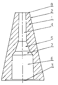
igure 1 shows an outer body of a gas-fluxing stone in
longitudinal section,
Figure 2 shows a view along line II-II of Figure 1,
Figure 3 shows a gas-fluxing stone in perspective,
igure 4 shows a plan view of the patterns which become
visible in the case of the gas-fluxing stone of
Figure 3 in the course of wear,
igure 5 shows a third exemplified embodiment of a gas-
fluxing stone, and
igure 6 shows a fourth exemplified embodiment of a gas-
fluxing stone.
A gas-fluxing stone according to Figure 1 has an outer body ~
having a conical surface shell 2. At the interior of the outer
body 1, a separator space 3 is provided. The latter has section
of different shapes at di~ferent elevations. Top section 4 is
circular--cylindrical. The section 5 connected thereto is
conically square. Bottom section 6 is circular-cylindrical. A
~ ~ '

~3272~
transition section 7 is provided between the section 6 and the
section 5.
The separator space 3 is filled with a gas-permeable material.
When natural gas is passed through the separator space 3, a
circular flame pattern is formed on the surface 8. During the
through-passage of the gas, this continues for as long as the
wear has not progressed beyond the section 4. I~ the wear has
advanced into the region of the section 5, a square flame pattern
is formed. This is an indication of substantially advanced wear.
In the case of continuing wear reaching into the bottom section
6, a circular flame pattern again appears, the diameter of which
is, however, considerably larger than the diameter of section 4.
It is also possible to insert an inner body into the interior
space of the outer body 1. The separator space 3 is then formed
by a gap or joint between the outer body 1 and the inner body.
In this instance, this will result in a corresponding annular
flame pattern during the through-passage of the gas.
In the case of the exemplified embodiment according to Figure 3,
an inner body 9 is inserted ln the outer body 1. rrhe separator
space 3, in the form of a gas-permeable joint, is provided
between the inner body 9 and the outer body 1. The outer body
1 and the inner body 9 are spaced equidistantly in all regions.
In its upper section 4, the inner body 9 is designed to be'
frusto-conical. Its bottom section 6 is designed to be
parallelepipedal. An appropriate transition section 7 is
~' ,

~272~
provided between these sections 4, 6. The separator space 3 can
have a hollow form corresponding to the outer body 1.
During the through~low of gas and while the bodies 1 and 9 are
not yet worn, a gas haze emerges on the surface 8, producing a
flame pattern which, in top view, appears circular-ring shaped
~cf. Figure 4a).
When the wear has advanced to the elevation b, a flame pattern
corresponding to Figure 4b in the basic form of a square with
rounded-off corners is produced. In the case of wear having
advanced to the elevation c, the plan view of the flame pattern
is square with sharp corners (cf. Figure 4c).
In the case of the gas-fluxing stone according to Figure 5, an
iron shell 10 forms the outer body 1. Disposed within the iron
shell 10, as the inner body 9, is a fluxing-stone upper part 11
and a fluxing-stone bottom part 12. The separator space 3 is
disposed between the iron shell 10 and the fluxing-stone upper
part 11, as well as bet~een the fluxing-stone upper part 11 and
the fluxing-stone bottom part 12. Between the iron shell 10 and
the fluxing-stone upper part 11, the separator space 3 is formed
by joints 13. Between the fluxing-stone upper part 11 and the
fluxing stone bottom part 12, hiyhly permeable material, for
example having a permeability in excess of 50 nPm, is inserted
in the separator space. Compared therewith, the fluxing-stone
upper part 11 and the fluXing-stone bottom part 12 are
impermeable, or slightly permeable, respectively.
,

7 13~72~`8
~he iron shell 10 is shrunk on to the fluxing-stone bottom part
12 or is tightly connected thereto by means of ~ cemented joint
14.
If scavenging gas i5 passed by a gas supply 15 through the gas-
~luxing stone, a circular ring, which is dark in comparison with
the light red surface 8 9f the fluxing-stone upper part 11, is
visible in the region of the fluxing joint 13, as a result of the
cooling effsct of the scavenging gas. If the fluxing-stone upper
part 11 is worn up to the elevation b, then a dark circular spot
is visible. This is an indication that the gas-fluxing stone
must be replaced.
The exemplified embodiment according to Figure 6-is similar to
that of Figure 5. In this case, an insert 16 having capillary
tubes is mounted in the fluxing-stone bottom part 12. Gas ducts
17 extend star-like radially outwards between the fluxing-stone
upper part 11 and the fluxing stone bottom part 12. Accordingly,
in the event of wear, a dark star is visiblè up to the elevation
b.
,
,

Dessin représentatif
Une figure unique qui représente un dessin illustrant l'invention.
États administratifs

2024-08-01 : Dans le cadre de la transition vers les Brevets de nouvelle génération (BNG), la base de données sur les brevets canadiens (BDBC) contient désormais un Historique d'événement plus détaillé, qui reproduit le Journal des événements de notre nouvelle solution interne.

Veuillez noter que les événements débutant par « Inactive : » se réfèrent à des événements qui ne sont plus utilisés dans notre nouvelle solution interne.

Pour une meilleure compréhension de l'état de la demande ou brevet qui figure sur cette page, la rubrique Mise en garde , et les descriptions de Brevet , Historique d'événement , Taxes périodiques et Historique des paiements devraient être consultées.

Historique d'événement

Description Date
Inactive : Périmé (brevet sous l'ancienne loi) date de péremption possible la plus tardive 2011-03-01
Lettre envoyée 2006-05-02
Inactive : CIB de MCD 2006-03-11
Inactive : Lettre officielle 2006-02-27
Inactive : Renversement de l'état réputé périmé 2003-03-20
Le délai pour l'annulation est expiré 2002-03-01
Inactive : Lettre officielle 2001-03-14
Lettre envoyée 2001-03-01
Lettre envoyée 2000-03-01
Accordé par délivrance 1994-03-01

Historique d'abandonnement

Il n'y a pas d'historique d'abandonnement

Titulaires au dossier

Les titulaires actuels et antérieures au dossier sont affichés en ordre alphabétique.

Titulaires actuels au dossier
DIDIER-WERKE A.G.
Titulaires antérieures au dossier
HANS ROTHFUSS
HERBERT METZGER
MANFRED WINKELMANN
Les propriétaires antérieurs qui ne figurent pas dans la liste des « Propriétaires au dossier » apparaîtront dans d'autres documents au dossier.
Documents

Pour visionner les fichiers sélectionnés, entrer le code reCAPTCHA :


Pour visualiser une image, cliquer sur un lien dans la colonne description du document. Pour télécharger l'image (les images), cliquer l'une ou plusieurs cases à cocher dans la première colonne et ensuite cliquer sur le bouton "Télécharger sélection en format PDF (archive Zip)" ou le bouton "Télécharger sélection (en un fichier PDF fusionné)".

Liste des documents de brevet publiés et non publiés sur la BDBC .

Si vous avez des difficultés à accéder au contenu, veuillez communiquer avec le Centre de services à la clientèle au 1-866-997-1936, ou envoyer un courriel au Centre de service à la clientèle de l'OPIC.


Description du
Document 
Date
(aaaa-mm-jj) 
Nombre de pages   Taille de l'image (Ko) 
Revendications 1994-07-20 2 48
Abrégé 1994-07-20 1 17
Dessins 1994-07-20 5 103
Description 1994-07-20 6 219
Dessin représentatif 2001-08-20 1 8
Avis concernant la taxe de maintien 2000-03-28 1 178
Avis concernant la taxe de maintien 2001-03-28 1 178
Correspondance reliée au PCT 1993-12-05 1 30
Correspondance de la poursuite 1992-05-28 6 167
Demande de l'examinateur 1992-02-05 1 70
Courtoisie - Lettre du bureau 1989-04-27 1 37
Taxes 2000-02-17 1 173
Taxes 2001-02-17 1 163
Correspondance 2001-03-13 7 297
Correspondance 2006-02-26 1 17
Correspondance 2006-05-01 1 14
Correspondance 2006-04-24 1 33
Taxes 1997-02-16 1 80
Taxes 1996-02-19 1 79