Note : Les descriptions sont présentées dans la langue officielle dans laquelle elles ont été soumises.
t 33645~
HARMONIC SPEECH CODING ARRANGEMENT
Technical Field
This invention relates to speech processing.
Background and Problem
Accurate representations of speech have been demonstrated using
harmonic models where a sum of sinusoids is used for synthesis. An analyzer
partitions speech into overlapping frames, E~mming windows each frame,
constructs a magnitude/phase spectrum, and locates individual sinusoids. The
correct m~gnitllde, phase, and frequency of the sinusoids are then tr3n~mittç~1 to a
10 synthesizer which generates the synthetic speech. In an unqu~nti7ed harmonic
speech coding system, the resulting speech quality is virtually transparent in that
most people cannot distinguish the original from the synthetic. The difficulty in
applying this approach at low bit rates lies in the necessity of coding up to 80harmonics. (The sinusoids are referred to herein as harmonics, although they are15 not always harmonically related.) Bit rates below 9.6 kilobits/second are typically
achieved by incorporating pitch and voicing or by dropping some or all of the
phase information. The result is synthetic speech differing in quality and
robustness from the unquantized version.
One approach typical of the prior art is disclosed in R. J. McAulay
20 and T. F. Quatieri, "Multirate sinusoidal transform coding at rates from 2.4 kbps
to 8 kbps," Proc. EEE Int. Conf. Acoust., Speech, and Si~nal Proc., vol. 3,
pp. 1645-1648, April 1987. A pitch detector is used to determine a filnd:3m~ntalpitch and the speech spectrum is modeled as a line spectrum at the determined
pitch and multiples thereof. The value of the determined pitch is tr~n~mittP-l from
25 the analyzer to the synthesizer which reconstructs the speech as a sum of
sinusoids at the filnd~m~ntal frequency and its multiples. The achievable speechquality is limited in such an arrangement, however, since substantial energy of the
input speech is typically present between the lines of the line spectrum and
because a separate approach is required for unvoiced speech.
In view of the foregoing, a recognized problem in the art is the
reduced speech quality achievable in known harmonic speech coding arrangements
where the spectrum of the input speech is modeled as only a line spectrum--for
example, at only a small number of frequencies or at a fllnd~mental frequency and
its multiples.
35 Solution
- 1 336456
- 2 -
The foregoing problem is solved and a technical advance is achieved
in accordance with the principles of the invention in a harmonic speech coding
arrangement where the m~gnitll(le spectrum of the input speech is modeled at theanalyzer by a relatively small set of p~llelel~, and, significantly, as a continuous
5 rather than only a line m~gninlde spectrum. The synthesizer, rather than the
analyzer, determines the magnitude, frequency, and phase of a large number of
sinusoids which are summed to generate synthetic speech of improved quality.
Rather than receiving information explicitly defining the sinusoids from the
analyzer, the synthesizer receives the small set of parameters and uses those
10 parameters to determine a spectrum, which in turn, is used by the synthesizer to
determine the sinusoids for synthesis.
At an analyzer of a harmonic speech coding arrangement, speech is
processed in accordance with a method of the invention by first determining a
m~gnitu-l.o spectrum from the speech. A set of parameters is then calculated
15 modeling the determined m~gnitllde spectrum as a continuous m~gnitllde spectrum
and the parameter set is comm-lni~ated for use in speech synthesis.
At a synthesizer of a harmonic speech coding arrangement, speech is
synthesized in accordance with a method of the invention by receiving a set of
parameters and determining a spectrum from the p~ameler set. The spectrum is
20 then used to determine a plurality of sinusoids, where the sinusoidal frequency of
at least one sinusoid is determined based on amplitude values of the spectrum.
Speech is then synthesized as a sum of the sinusoids.
At the analyzer of an illustrative h~nnonic speech coding arrangement
described herein, the m~gnitllcle spectrum is modeled as a sum of four functions25 comprising the estim~ted m~gninlde spectrum of a previous frame of speech, a
m~gnitude spectrum of a first periodic pulse train, a m~gninlde spectrum of a
second periodic pulse train, and a vector chosen from a codebook. The parameter
set is calculated to model the mzlgnitllde spec~ m in accordance with a minimllmmean squared error criterion. A phase spectrum is also determined from the
30 speech and used to calculate a second set of p~l~ters modeling the phase
spectrum as a sum of two functions comprising a phase estimate and a vector
chosen from a codebook. The phase estimate is determined by performing an all
pole analysis, a pole-zero analysis and a phase prediction from a previous frameof speech, and selecting the best estimate in accordance with an error criterion.
35 The analyzer determines a plurality of sinusoids from the m~gninlde spectrum for
use in the phase estimation, and matches the sinusoids of a present frame with
1 S36456
-- 3 --
those of previous and subsequent frames using a m~tching criterion that takes into
account both the amplitude and frequency of the sinusoids as well as a ratio of
pitches of the frames.
At the synthesizer of the illustrative harmonic speech coding
S arrangement, an estim~t~-l m~gnit~ e spectrum and an estim~t~d phase spectrum
are determined based on the received parameters. A plurality of sinusoids is
determined from the estimated m~gnitllde spectrum by finding a peak in that
spectrum, subtracting a spectral component associated with the peak, and
repeaLillg the process until the esfim~t~d m~gnit~ltle spectrum is below a threshold
10 for all frequencies. The spectral component comprises a wide magnitude spectrum
window defined herein. The sinusoids of the present frame are matched with
those of previous and subsequent frames using the same matching criterion used at
the analyzer. The sinusoids are then constructed having their sinusoidal amplitude
and frequency determined from the estim~ted m~gni~lde spectrum and their
15 sinusoidal phase determined from the estim~ted phase spectrum. Speech is
synthesized by sllmming the sinusoids, where interpolation is performed between
matched sinusoids, and lmm~tch~d sinusoids remain at a constant frequency.
In accordance with one aspect of the invention there is provided in a
harmonic speech coding arrangement, a method of processing speech signals, said
20 speech signals comprising frames of speech, said method comprising determinin~
from a present one of said frames a m~gnit~lde spectrum having a plurality of
s~ecLl~n points, the frequency of each of said spectrum points being independentof said speech signals, calclll~fin~ a set of parameters for a continuous m~gnitl1cle
spectrum that models said de~ cl m~gnitll(le spectrum at each of said
25 spectrum points, the number of parameters of said set being less than the number
of said spectrum points, said continuous m~gnihlde spectrum comprising a sum of
a plurality of functions, one of said functions being a m~gnitllde spectrum for a
previous one of said frames, encoding said set of parameters as a set of parameter
signals representing said speech signals, co~ "ll~icating said set of parameter
30 signals representing said speech signals for use in speech synthesisj and
synthesizing speech based on said co",l"lll~ tecl set of parameter signals.
3 1 336456
- a-
In accordance with another aspect of the invention there is provided in
a harmonic speech coding arrangement, apparatus comprising means responsive to
speech signals for d~tel,llillil~g a m~gnihlde spectrum having a plurality of
spectrum points, said speech signals comprising frames of speech, said determining
means determining said m~gninlde spectrum having a plurality of spectrum points
from a present one of said frames, means responsive to said determining means
for calcnl~ting a set of parameters for a continuous m~gnit~lde spectrum that
models said determined m~gninlde spectrum at each of said spectrum points, the
number of parameters of said set being less than the number of said spectrum
points, said continuous m~gnihl~ spectrum comprising a sum of a plurality of
functions, one of said functions being a m~gnihlde spectrum for a previous one of
said frames, means for encoding said set of parameters as a set of parameter
signals representing said speech signals, means for co"""lll-ic~ting said set ofparameter signals representing said speech signals for use in speech synthesis, and
means for synth~si7ing speech based on said set of parameter signals
collll~ll"~ic~tçd by said co~ llic~ting means.
Detailed Deselil,lion
FIG. 1 is a block diagram of an exemplary harmonic speech coding
arrangement in accordance with the invention;
FIG. 2 is a block diagram of a speech analyzer included in the
arrangement of FIG. l;
FIG. 3 is a block diagram of a speech synthesizer included in the
arrangement of FIG. l;
FIG. 4 is a block diagram of a m~gnihlrle qll~nti7er included in the
analyzer of FIG. 2;
FIG. 5 is a block diagram of a m~gnihlde s~ecllul~l estim~tor included
in the synthPsi7~r of FIG. 3;
FIGS. 6 and 7 are flow charts of exemplary speech analysis and speech
synthesis programs, respectively;
FIGS. 8 through 13 are more detailed flow charts of routines included
in the speech analysis program of FIG. 6;
FIG. 14 is a more ~et~ilel1 flow chart of a routine included in the
speech synthesis program of FIG. 7; and
r~
-
1 336456
- 4 -
FIGS. 15 and 16 are flow charts of alternative speech analysis and
speech synthesis prograrns, respectively.
General Description
The approach of the present harmonic speech coding arrangement is to
5 transmit the entire complex spectrum instead of sending individual harmonics.
One advantage of this method is that the frequency of each harmonic need not be
tr~n~mitte~l since the synthesizer, not the analyzer, estimates the frequencies of the
sinusoids that are summed to gel1cldte synthetic speech. Harmonics are found
directly from the m~gnitude spectrum and are not required to be harmonically
10 related to a filnd~m~ntal pitch.
To transmit the continuous speech spectrum at a low bit rate, it is
necessary to characterize the spectrum with a set of continuous functions that can
be described by a small number of parameters. Functions are found to match the
m~gnitl1rle/phase spectrum co~llputed from a fast Fourier transform (FFT) of the15 input speech. This is easier than fitting the reaVim~gin~ry spectrum because
special re~ nd~ncy characteristics may be exploited. For example, m~gnitude and
phase may be partially predicted from the previous frame since the m~gnitude
spectrum remains relatively constant from frame to frame, and phase increases at a
rate pl~olLional to frequency.
Another useful function for ~cpl~sellling m~gninlde and phase is a
pole-zero model. The voice is modeled as the response of a pole-zero filter to
ideal impulses. The m~gnitude and phase are then derived from the filter
p~dlllete.~. Error ~...~ining in the model estimate is vector qu~nti7~1 Once thespectra are matched with a set of functions, the model parameters are tr~nsmitte~l
25 to the synthesi7-o,r where the spectra are reconstructed. Unlike pitch and voicing
based strategies, performance is relatively insensitive to parameter estimation
errors.
In the illustrative embodiment described herein, speech is coded using
the following procedure:
30 Analysis
1. Model the complex spectral envelope with poles and zeros.
2. Find the m~gnitude spectral envelope from the complex envelope.
3. Model fine pitch structure in the m~gnitude spectrum.
4. Vector quantize the remaining error.
35 5. Evaluate two methods of modeling the phase spectrum:
l 336456
a. Derive phase from the pole-zero model.
b. Predict phase from the previous frame.
6. Choose the best method in step 5 and vector quantize the residual error.
7. Transmit the model pa~ cte
5 Synthesis:
1. Reconstruct the m~gnit~lde and phase spectra.
2. Determine the sinusoidal frequencies from the m~gnit~lde spectrum.
3. Generate speech as a sum of sinusoids.
Modeling The l~nit~lde Spectrum
To represent the spectral m~gnit~lde with as few parameters as
possible, advantage is taken of redllnd~ncy in the spectrum. The m~nit~lde
spect;um consists of an envelope defining the general shape of the spectrum and
approximately periodic components that give it a fine structure. The smooth
m~gnitufie spectral envelope is represented by the m~gninl-le response of an all-
15 pole or pole-zero model. Pitch detectors are capable of representing the finestructure when periodicity is clearly present but often lack robustness under non-
ideal conditions. In fact, it is difficult to find a single p~dlllcLlic function that
closely fits the m~gnitude spectrum for a wide variety of speech characteristics. A
reliable estimate may be constructed from a weighted sum of several functions.
20 Four functions that were found to work particularly well are the estim~ted
m~gnit~lde s~ecllu~ll of the previous frame, the m~gnit~lde spectrum of two
periodic pulse trains and a vector chosen from a codebook. The pulse trains and
the codeword are ~mming windowed in the time domain and weighted in the
frequency domain by the m~gnitude envelope to preserve the overall shape of the
25 spectrum. The oplilllum weights are found by well-known mean squared error
(MSE) ~ i-,.;7~l;on techniques. The best frequency for each pulse train and the
optimum code vector are not chosen simlllt~neously. Rather, one frequency at at
time is found and then the codeword is chosen. If there are m functions di(~),
l~i<m, and coll.,.yonding weights ai,m, then the esli,llate of the m~nitude
30 spectrum IF(~)I is
IF(~3)l = ~aimdi(~) (1)
i= 1
Note that the m~gnit~lde spectrum is modeled as a continuous spectrum rather than
a line spectrum. The OplimUlll weights are chosen to minimi7e
1 33645~
~D, / 2 ~ 2
J I F(c~ , aimd~ ) do, (2)
O _ i=l _
where F(co) is the speech spectrum, ~s is the sampling frequency, and m is the
number of functions included.
The frequency of the first pulse train is found by testing a range
S (40 - 400 Hz) of possible frequencies and selecting the one that minimi7es (2) for
m=2. For each c~n~ te frequency, optimal values of ai,m, are compu~ed. The
process is repeated with m=3 to find the second frequency. When the m~gnitlld~
spectrum has no periodic structure as in unvoiced speech, one of the pulse trains
often has a low frequency so that windowing effects cause the associated spectrum
10 to be relatively smooth.
The code vector is the entry in a codebook that minimi7es (2) for
m=4 and is found by searching. In the illustrative embodiment described herein,
codewords were constructed from the FFT of 16 sinusoids with random
frequencies and amplitudes.
lS Phase Modeling
Proper representation of phase in a sinusoidal speech synthesizer is
important in achieving good speech quality. Unlike the m~gninlde spectrum, the
phase spectrum need only be matched at the harmonics. Therefore, harmonics are
determined at the analyzer as well as at the synthesizer. Two methods of phase
20 estimation are used in the present embodiment. Both are evaluated for each
speech frame and the one yielding the least error is used. The first is a parametric
method that derives phase from the spectral envelope and the location of a pitchpulse. The second ass~lm~s that phase is continuous and predicts phase from thatof the previous frame.
Homomorphic phase models have been proposed where phase is
derived from the m~gnit~lde s~ectrulll under assumptions of ...ini.~ phase. A
vocal tract phase function q~k may also be derived directly from an all-pole model.
The actual phase k of a harmonic with frequency ~k iS related to ~k by
~k = ~k~ k+ 2~ ~k (3)
30 where to is the location in time of the onset of a pitch pulse, ~ is an integer, and
~k is the estimation error or phase residual.
The variance of ~k may be substantially reduced by replacing the all-
pole model with a pole-zero model. Zeros aid representation of nasals and speechwhere the shape of the glottal pulse deviates from an ideal impulse. In
35 accordance with a method that minimi7es the complex spectral error, a filter
1 336456
- 7 -
H(c~k) consisting of p poles and q zeros is specified by coefficients ai and b
where
~biej
~aiei'~
i=o
The oplimulll filter minimi7~s the total squared spectral error
Es = ~, I e j~to H((dk) - F(CI)k) I 2. (5)
k=l
Since H(~3k) models only the spectral envelope, Ct~k, l<k~K, corresponds to peaks
in the magnitude ~l~ecL~ulll. No closed form solution for this expression is known
so an iterative approach is used. The impulse is located by trying a range of
values of to and selecting the value that minimi7es Es~ Note that H(~k) is not
10 constrained to be minimllm phase. There are cases where the pole-zero filter
yields an accurate phase specL~um, but gives errors in the m~gnin1de spectrum.
The simplest solution in these cases is to revert to an all-pole filter.
The second method of estimating phase assumes that frequency
changes linearly from frame to frame and that phase is continuous. When these
15 conditions are met, phase may be predicted from the previous frame. The
estimated increase in phase of a harmonic is tc~k where ~k iS the average
frequency of the harmonic and t is the time belw~ell frames. This method works
well when good estimates for the previous frame are available and harmonics are
accurately matched between frames.
After phase has been estim~ted by the method yielding the least error,
a phase residual k remains. The phase residual may be coded by replacing ~k
with a random vector ~Irc,k- l<c<C, selected from a codebook of C codewords.
Codeword selection consists of an exhaustive search to find the codeword yielding
the least mean squared error (MSE). The MSE between two sinusoids of identical
25 frequency and amplitude Ak but differing in phase by an angle vk is
Ak[l - cos(vk)]. The codeword is chosen to minimi7e
~ Ak[l --Cos(~k --~c,k)] (6)
k= 1
This criterion also determines whether the parametric or phase prediction estim~te
is used.
1 336456
- 8 -
Since phase resid~ in a given spectrum tend to be uncorrelated and
normally distributed, the codewords are constructed from white Gaussian noise
sequences. Code vectors are scaled to minimi7e the error although the scaling
factor is not always optimal due to nonlinearities.
5 Harmonic Matchin~
Correctly matching harmonics from one frame to another is
particularly hllp~lL~lt for phase prediction. Matching is complicated by
f~lnll~mental pitch variation between frames and false low-level harmonics caused
by sidelobes and window subtraction. True harmonics may be distinguished from
10 false harmonics by incorporating an energy criterion. Denote the amplitude of the
kdl harmonic in frame m by Akm). If the energy norm~li7e~1 amplitude ratio
[A(m)]2/ ~ [Ai(m)]2 / [A~m-l)]2/ ~, [A~m-1)]2
i= 1 i= 1
or its inverse is greater than a fixed threshold, then Akm) and A~m- 1) likely do not
correspond to the same harmonic and are not matched. The ~Lilllulll threshold is15 e~l)el;",ellt~lly determined to be about four, but the exact value is not critical.
Pitch changes may be taken into account by estimating the ratio ~ of
the pitch in each frame to that of the previous frame. A harmonic with frequencycom~ is considered to be close to a harmonic of frequency ~km- 1) if the adjusted
dirr.,.~,nce frequency
I C~km) ~ m-l) I (8)
is small. Harmonics in adjacent frames that are closest according to (8) and have
similar amplitudes according to (7) are matched. If the correct matching were
known, ~ could be estim~te~ from the average ratio of the pitch of each harmonicto that of the previous frame weighted by its amplitude
r = ~ K 2 C~)Lm 1)
i = 1
The value of ~ is unknown but may be approximated by initially letting y equal
one and iteratively matching harmonics and updating ~ until a stable value is
found. This procedure is reliable during rapidly changing pitch and in the
presence of false harmonics.
30 Synthesis
A unique feature of the parametric model is that the frequency of each
sinusoid is determined from the m~gnitu(le spectrum by the synthesizer and need
not be tr:~n~mitte~l Since windowing the speech causes spectral spreading of
1 33645~
g
harmonics, frequencies are estim~ted by locating peaks in the spectlum. Simple
peak-picking algoli~hllls work well for most voiced speech, but result in an
unnatural tonal quality for unvoiced speech. These impairments occur because,
during unvoiced speech, the number of peaks in a spectral region is related to the
5 smoothness of the spectrum rather than the spectral energy.
The concentration of peaks can be made to correspond to the area
under a spectral region by subtracting the contribution of each harmonic as it is
found. First, the largest peak is assumed to be a harmonic. The m~gnitude
spectrum of the scaled, frequency shifted E~mming window is then subtracted
10 from the m~gninlde spectrum of the speech. The process repeats until the
m~nit~lcle spectrum is reduced below a threshold at all frequencies.
When frequency estimation error due to ~ l resolution causes a peak
to be estim~te~i to one side of its tlue location, portions of the spectrum remain on
the other side after window subtraction, resulting in a spurious harmonic. Such
15 artifacts of frequency errors within the resolution of the ~ l may be elimin~ted
by using a modified window transform W'i = max(Wi_l,Wi,Wi+l), where Wi is a
sequence representing the FFT of the time window. W'i is referred to herein as awide magnitude spectrum window. For large FFT sizes, W'i approaches Wi.
To prevent discontinuities at frame boundaries in the present
20 embodiment, each frame is windowed with a raised cosine function overlapping
halfway into the next and previous frames. Harmonic pairs in adjacent frames
that are matched to each other are linearly interpolated in frequency so that the
sum of the pair is a continuous sinusoid. Unmatched harmonics remain at a
constant frequency.
25 Detailed Description
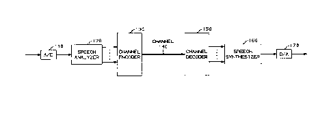
An illustrative speech processing arrangement in accordance with the
invention is shown in block diagram form in FIG. 1. Incoming analog speech
signals are converted to digitized speech samples by an A/D converter 110. The
~1igiti7ed speech samples from converter 110 are then processed by speech
30 analyzer 120. The results obtained by analyzer 120 are a number of parameterswhich are tr~n~mitted to a channel encoder 130 for encoding and tr~n~mi~sion
over a channel 140. A channel decoder 150 receives the q-l~nti7ed parameters
from channel 140, decodes them, and transmits the decoded parameters to a
speech synthesizer 160. Synthesizer 160 processes the palalllcters to generate
35 digital, synthetic speech samples which are in turn processed by a D/A converter
170 to reproduce the incoming analog speech signals.
1 336456
- 10 -
A number of equations and expressions (10) through (26) are
presented in Tables 1, 2 and 3 for convenient reference in the following
description.
I 336456
1 1 -
3W i=o (10)
H(~k) = p (11)
~aiej~i
=o
~ [IH(~3k)l -- IF(C~k)l] (12)
k=l
alphal = oldalphal + 3 (13)
fl = 40ealPhal~ln(lo) (14)
2s6 2
El = ~ IF(k)l - ~ai,2di(k) (15)
k=O _ i= 1 _
alpha2 = oldalpha2 + (16)
(SR2)3
TABLE 1
1 336456
f2 = 40ealpha2~ o) (17)
2s6 3 2
E2 = ~, IF(k)l - ~ai,3di(k) (18)
k=O _ i= 1
2s6 4 2
E3 = ~, IF(k)l - ~,ai,4di(k) (19)
k=O _ i= 1
S I F(c~ ai,4d~ )) (20)
i=l
K [Akm)]2 c~km)
~[Ai ] (21)
k) = arg [eiQ~tH(~k)] (22)
Ep = ~,Ak[l --cos(~(~k)--~ )k))] (23)
10 k=l
TABLE 2
1 336456
- 13 -
~Ak[l - COS(O(~k) - ~(~k) - Yc~c,k)] (24)
k=l
~(~k) = arg[ej H(~k)] +~c ~c,k (25)
m) + ~m 1)
~m(~k) = 2 t + ~c ~c,k (26)
s
TABLE 3
Speech analyzer 120 iS shown in greater detail in FIG. 2.
10 Converter 110 groups the digital speech samples into overlapping frames for
tr~n~mi~ion to a window unit 201 which H~mming windows each frame to
generate a sequence of speech samples, si. The framing and windowing
techniques are well known in the art. A spectrum generator 203 pelru~ s an
of the speech samples, si, to determine a m~gnitude spectrum, I F(~3) 1, and a
15 phase spectrum, 0(~). The FFT pclrc.,llled by spectrum generator 203 comprises
a one-dimensional Fourier transform. The determined m~gnit~lde spectrum I F(c
is an interpolated spectrum in that it comprises a greater number of frequency
samples than the number of speech samples, si, in a frame of speech. The
interpolated spectrum may be obtained either by zero padding the speech samples
20 in the time domain or by interpolating between adjacent frequency samples of a
nonint~olated spectrum. An all-pole analyzer 210 processes the windowed
speech samples, si, using standard linear predictive coding (LPC) techniques to
obtain the parameters, ai, for the all-pole model given by equation (11), and
performs a sequential evaluation of equations (22) and (23) to obtain a value of25 the pitch pulse location, to, that minimi7es Ep. The parameter, p, in equation (11)
is the number of poles of the all-pole model. The frequencies C)k used in
equations (22), (23) and (11) are the frequencies C)'k determined by a peak
detector 209 by simply locating the peaks of the m~gnitllde spectrum I F(c~) I .Analyzer 210 transmits the values of ai and to obtained together with zero values
30 for the palalllelels, bi, (corresponding to zeroes of a pole-zero analysis) to a
selector 212. A pole-zero analyzer 206 first determines the complex spectrum,
-~ 1 336456
- 14 -
F(c~), from the m~gni~lde spectrum, I F(cd)l, and the phase spectrum, O(c3).
Analyzer 206 then uses linear methods and the complex spectrum, F(c,~), to
determine values of the parameters ai, bi, and to to minimi7e Es given by equation
(5) where H(c~k) is given by equation (4). The parameters, p and z, in
5 equation (4) are the number of poles and zeroes, respectively, of the pole-zero
model. The frequencies Cl~k used in equations (4) and (5) are the frequencies C)'k
determined by peak detector 209. Analyzer 206 transmits the values of ai, bi, and
to to selector 212. Selector 212 evaluates the all-pole analysis and the pole-zero
analysis and selects the one that minimi7es the mean squared error given by
10 equation (12). A qll~nti7~r 217 uses a well-known qu~nti7~tion method on the
p~dl~le~el~ selected by selector 212 to obtain values of qu~nti7~ parameters, ai,
bi, and to, for encoding by channel encoder 130 and tr~ncmicsion over
channel 140.
A m~gnitllde qu~nti7.or 221 uses the qu~nti7ed parameters ai and bi,
15 the m~gnitllde spectrum I F(c~)l, and a vector, ~d,k. selected from a codebook 230
to obtain an estim~ted m~gnit~lde spectrum, I F(c3)1, and a number of palametersal,4, a2,4, a3,4, a4.4, fl, f2. ~gnit~lde qll~nti7er 221 is shown in greater detail
in FIG. 4. A summer 421 generates the estimated m~gnitude spectrum, lF(cl))l,
as the weighted sum of the estimated m~gnitllde spectrum of the previous frame
20 obtained by a delay unit 423, the m~gnitude spectrum of two periodic pulse trains
generated by pulse train transform generators 403 and 405, and the vector, ~d,k.selected from codebook 230. The pulse trains and the vector or codeword are
~mming windowed in the time dom~in, and are weighted, via spectral
multipliers 407, 409, and 411, by a m~gnitl~de spectral envelope generated by a
25 generator 401 from the q~l~nti7ed parameters ai and bi. The generated functions
dl(o), d2(c~), d3(~l)), d4(o) are further weighted by multipliers 413, 415, 417,and 419 respectively, where the weights al,4, a2,4, a3,4, ~X4,4 and the frequencies
fl and f2 of the t~,vo periodic pulse trains are chosen by an optimizer 427 to
minimi7e equation (2).
A sinusoid finder 224 (E~IG. 2) determines the amplitude, Ak, and
frequency, tl)k. of a number of sinusoids by analyzing the estimated m~gnitude
A A
spectrum, IF(~)I. Finder 224 first finds a peak in I F(c~)) I . Finder 224 then
constructs a wide m~gnitllde spectrum window, with the same amplitude and
frequency as the peak. The wide m~gnitll~e spectrum window is also referred to
35 herein as a modified window transform. Finder 224 then subtracts the spectralcomponent comprising the wide m~gnit~lde spectrum window from the estimated
- 1 336456
- 15 -
m~gnitllAe spectrum, I F(c~) I . Finder 224 repeats the process with the next peak
until the estimated m~gnitll(le spectrum, I F(~,) I, is below a threshold for all
frequencies. Finder 224 then scales the h~rmo,nics such that the total energy ofthe harmonics is the same as the energy, nrg, determined by an energy
5 calculator 208 from the speech samples, si, as given by equation (10). A sinusoid
matcher 227 then generates an array, BACK, defining the association between the
sinusoids of the present frame and sinusoids of the previous frame matched in
accordance with equations (7), (8), and (9). Matcher 227 also gen~dles an array,LINK, dçfining the association between the sinusoids of the present frame and
10 sinusoids of the subsequent frame matched in the same manner and using well-
known frame storage techniques.
A p~dllæLIic phase estim~tor 235 uses the q~l~nti7eA paldmelers ai, bi,
and to to obtain an e~ llated phase spectrum, ~O(c~,), given by equation (22). Aphase predictor 233 obtains an estimated phase spectrum, ~1 (~), by prediction
15 from the previous frame assuming the frequencies are linearly interpolated. Aselector 237 selects the estim~teA phase spectrum, ~ ,), that ~ ;,.li7es the
weighted phase error, given by equation (23), where Ak is the amplitude of each
of the sinusoids, ~3(Ct',k) iS the true phase, and ~3(Ct~',k) iS the estimated phase. If the
pald,ll~Llic method is selected, a p~dllletcr, phasemethod, is set to zero. If the
20 prediction method is selected, the parameter, phasemethod, is set to one. An
arrangement compri~ing ~.ull~ller 247, multiplier 245, and optimizer 240 is used to
vector quantize the error re~n~ining after the selected phase estimation method is
used. Vector ql1~nti7~tiQn consists of replacing the phase residual comprising the
difference between (~l3k) and ~(~k) with a random vector ~C,k selected from
25 codebook 243 by an çl~h~llstive search to determine the codeword that minimi7es
mean squared error given by equation (24). The index, Il, to the selected vector,
and a scale factor ~c are thus determined. The resultant phase spectrum is
genclaled by a s7umlll~l 249. Delay unit 251 delays the resultant phase spectrumby one frame for use by phase predictor 251.
Speech synthesi7~r 1~,0 is shown in greater detail in FIG. 3. The
received index, I2, is used to determine the vector, ~lld,k. from a codebook 308.
The vector, Yrd,k. and the received parameters al,4, a2,4, a3,4, a4,4, fl, f2, ai, bi
are used by a m~gnitllde sl,ec~lulll estimator 310 to determine the estimated
m~gnit~lde spectrum I F(c~) I in accordance with equation (1). The elements of
estimator 310 (FIG. 5)--501, 503, 505, 507, 509, 511, 513, 515, 517,
519, 521, 523--perform the same function that corresponding elements--401, 403,
- 1 336456
- 16 -
405, 407, 409, 411, 413, 415, 417, 419, 421, 423--perform in magnitllde
q~lanti7çr 221 (E~G. 4). A sinusoid finder 312 (FIG. 3) and sinusoid matcher 314perform the same functions in synthesi7er 160 as sinusoid finder 224 (FIG. 2) and
sinusoid matcher 227 in analyzer 120 to determine the amplitude, Ak, and
S frequency, k- of a number of sinusoids, and the arrays BACK and LINK,
defining the association of sinusoids of the present frame with sinusoids of theprevious and subsequent frames respectively. Note that the sinusoids determined
in speech synthesizer 160 do not have pred~Ftçrmined frequencies. Rather the
sin~lsoiAal frequencies are dependent on the pal~l~e~els received over channel 140
10 and are determined based on amplitude values of the estim~te~ magnitude
spectrum I F(~) 1. The sinusoidal frequencies are nonuniformly spaced.
A parametric phase e~ alol 319 uses the received pa~ ai, bi,
to, together with the frequencies CI)k of the sinusoids determined by sinusoid
finder 312 and either all-pole analysis or pole-zero analysis (p~.rolllled in the
15 same manner as described above with respect to analyzer 210 (FIG. 2) and
analyzer 206) to determine an estimatçd phase spectrum, ~0(c~). If the received
pal~lcters, bi, are all zero, all-pole analysis is pFIr~lnled. Otherwise, pole-zero
analysis is p~Çolllled. A phase predictor 317 (FIG. 3) obtains an estimated phase
spectrum, ~ )), from the arrays LINK and BACK in the same manner as phase
20 predictor 233 (FIG. 2). The estimated phase specLlulll is ~lçtenninçd by
estimator 319 or predictor 317 for a given frame dependent on the value of the
received parameter, pha~emFthoA If ph~emethod is zero, the estimated phase
spectrum obtained by estimator 319 is transmitteA via a selector 321 to a
F,. 327. If ph~emFthod is one, the e~ ~3 phase ~pe~l,ulll obtained by
25 predictor 317 is tran~mitted to su~ll~r 327. The selected phase spectrum is
combined with the product of the received pal~m~,ter, ~c, and the vector, ~c k, f
codebook 323 defined by the received index Il, to obtain a result~nt phase
spectrum as given by either equation (25) or equation (26) depending on the value
of ph~emFtho l The resultant phase s~cllulll is delayed one frame by a delay
30 unit 335 for use by phase predictor 317. A sum of sinusoids generator 329
constructs K sinusoids of length W (the frame length), frequency Cl)k. l~k<K,
amplitude Ak, and phase ~k. Sinusoid pairs in adjacent frames that are matched
to each other are linearly interpolated in frequency so that the sum of the pair is a
continuous sinusoid. Unmatched sinusoids remain at constant frequency.
35 Generator 329 adds the constructed sinusoids together, a window unit 331
windows the sum of sinusoids with a raised cosine window, and an
-- 1 336$56
- 17 -
overlap/adder 333 overlaps and adds with adjacent frames. The resulting digital
samples are then converted by D/A converter 170 to obtain analog, synthetic
speech.
FM. 6 is a flow chart of an illustrative speech analysis program that
5 pe,r ,lllls the functions of speech analyzer 120 (FIG. 1) and channel encoder 130.
In accordance with the example, L, the spacing bel~ ,n frame centers is 160
samples. W, the frame length, is 320 samples. F, the number of samples of the
FFT, is 1024 samples. The number of poles, P, and the nul~ of zeros, Z, used
in the analysis are eight and three, respectively. The analog speech is sampled at
10 a rate of 8000 samples per second. The digital speech samples received at
block 600 tFIG. 6) are processed by a TIME2POL routine 601 shown in detail in
FIG. 8 as comprising blocks 800 through 804. The window-norm~1i7e~1 energy is
col~u~ed in block 802 using equation (10). Processing proceeds from routine 601
(FIG. 6) to an ARMA routine 602 shown in detail in FIG. 9 as comprising
15 blocks 900 through 904. In block 902, Es is given by equation (5) where H(cq~)
is given by equation (4). Equation tll) is used for the all-pole analysis in
block 903. Expression (12) is used for the mean squared error in block 904.
P~-xessing proceeds from routine 602 tFIG. 6) to a QMAG routine 603 shown in
detail in FIG. 10 as comprising blocks 1000 through 1017. In block 1004,
20 equations (13) and (14) are used to coll-pu~e fl. In block 1005, El is given by
equation (15). In block 1009, equations (16) and (17) are used to com~ e f2. In
block 1010, E2 is given by equation (18). In block 1014, E3 is given by equation(19). In block 1017, the es~ t~ m~gnin1de spectrum, I F(~) I, is constructed
using equation (20). Proces~ing proceeds from routine 603 (FIG. 6) to a
25 MAG2LINE routine 604 shown in detail in FIG. 11 as compri~ing blocks 1100
through 1105. ~ocessil-g proceeds from routine 604 (FIG. 6) to a LINKLINE
routine 605 shown in detail in FIG. 12 as comprising blocks 1200 through 1204.
Sinusoid matching is p~ ed between the previous and present frames and
between the present and subsequent frames. The routine shown in FIG. 12
30 matches sinusoids ~ ,n frames m and (m - 1). In block 1203, pairs are not
similar in energy if the ratio given by e~piession (7) is less that 0.25 or greater
than 4Ø In block 1204, the pitch ratio, p, is given by equation (21). Processing
proceeds from routine 605 (FIG. 6) to a CONT routine 606 shown in detail in
FIG. 13 as comprising blocks 1300 through 1307. In block 1301, the estimate is
35 made by evaluating expression (22). In block 1303, the weighted phase elTor, is
given by equation (23), where Ak is the amplitude of each sinusoid, ~3(C)k) iS the
- 18- l 336456
true phase, and ~ ) is the estimated phase. In block 1305, mean squared error
is given by expression (24). In block 1307, the construction is based on equation
(25) if the parameter, phasemethod, is zero, and is based on equation (26) if
phasemethod is one. In equation (26), t, the time between frame centers, is given
5 by L/8000. Processing proceeds from routine 606 (FIG. 6) to an ENC routine 607 where the palallletel~ are encoded.
FIG. 7 is a flow chart of an illustrative speech synthesis program that
pelru~ s the functions of channel decoder 150 (FIG. 1) and speech
synthesizer 160. The pa~ c~ received in block 700 (FIG. 7) are decoded in a
10 DEC routine 701. Processing proceeds from routine 701 to a QMAG routine 702
which constructs the qu~nti7erl m~gnitllde ~ec~ I F (~) I based on
equation (1). Processing proceeds from routine 702 to a MAG2LINE routine 703
which is similar to MAG2LINE routine 604 (FIG. 6) except that energy is not
resc~l~l Processing proceeds from routine 703 (FIG. 7) to a LINKLINE
15 routine 704 which is similar to LINKLINE routine 605 (FIG. 6). Pr~ces~ing
proceeds from routine 704 (E~IG. 7) to a CONT routine 705 which is similar to
CONT routine 606 (FIG. 6), however only one of the phase esl;,.~l;on methods is
performed (based on the value of phasemethod) and, for the pal~le~lic estim~tion~
only all-pole analysis or pole-zero analysis is pelrolllled (based on the values of
20 the received parameters bi). Processing proceeds from routine 705 (FIG. 7) to a
SYNPLOT routine 706 shown in detail in FIG. 14 as comprising blocks 1400
through 1404.
FIGS. 15 and 16 are flow charts of alternative speech analysis and
speech synthesis programs, respectively, for harmonic speech coding. In FIG. 15,25 processing of the input speech begins in block 1501 where a spectral analysis, for
example finding peaks in a m~gnitu-le spectrum obtained by performing an ~ l, isused to ~etermine A~ , i for a plurality of sinusoids. In block 1502, a
palalllel~,r set 1 is ~let~rmine~1 in obtaining estim~tes, Ai, using, for example, a
linear predictive coding (LPC) analysis of the input speech. In block 1503, the
30 error between Ai and Ai is vector qll~nti7e~ in accordance with an error criterion
to obtain an index, IA. ~efining a vector in a codebook, and a scale factor, aA. In
block 1504, a parameter set 2 is determined in obtaining e~ es, C~i, using, for
example, a filn~ n~l frequency, obtained by pitch detection of the input
speech, and multiples of the fi~n~l~mental frequency. In block 1505, the error
35 bclween c~i and c3i is vector qll~nti7e 1 in accordance with an error criterion to
obtain an index, Ia" defining a vector in a codebook, and a scale factor a". In
- 1 336456
- 19 -
block 1506, a p~ tel set 3 is determined in obtaining estim~tes~ ~i, from the
input speech using, for example either parametric analysis or phase prediction as
described previously herein. In block 1507, the error between i and ~i is vector
qll~nti7yl in accordance with an error criterion to obtain an index, I~, defining a
S vector in a codebook, and a scale factor, a~. The various pa.~l~lel sets, indices,
and scale factors are encoded in block 1508. (Note that parameter sets 1, 2, and 3
are typically not disjoint sets.)
FIG. 16 is a flow chart of the alternative speech synthesis program.
Processing of the received pald,ne~el~ begins in block 1601 where pal~-,elel set 1
10 is used to obtain the essim~tes~ Ai. In block 1602, a vector from a codebook is
determined from the index, IA. scaled by the scale factor, aA, and added to Ai to
obtain Ai. In block 1603, p~al~te~ set 2 is used to obtain the estim~tes, c~i. In
block 1604, a vector from a codebook is determined from the index, ICD~ scaled by
the scale factor, a6D, and added to ~i to obtain ~i. In block 1605, a pa.~mete
lS set 3 is used to obtain the estim~tes, ~i. In block 1606, a vector from a codebook
is determined from the index, I~, and added to ~i to obtain i- In block 1607,
synthedc speech is generated as the sum of the sinusoids defined by Ai, c~i, i-
It is to be understood that the above-described harmonic speech
coding arrangelllel ts are merely illustrative of the principles of the present
20 invention and that many variations may be devised by those skilled in the artwithout departing from the spirit and scope of the invention. For example, in the
illustrative harmonic speech coding arrangements described herein, parameters are
co....~....-ir~te~l over a channel for synthesis at the other end. The arrangemecould also be used for efficient speech storage where the p~d-llet~l~ are
25 co....~ icatyl for storage in memory, and are used to generate synthetic speech at
a later time. It is thelerole intended that such variations be included within the
scope of the claims.