Note : Les descriptions sont présentées dans la langue officielle dans laquelle elles ont été soumises.
20~31269
The present invention relates to an apparatus for
electroplating or chemically treating metallic parts.
For reasons of completeness it should be understood that the
terms "electroplating" or "chemically treating" refer to any
kind of electroplating or chemical surface treatment or
application that does not involve the use of external current
of any kind, and which is used for bulky items and includes,
for example, nickel plating. Such an apparatus, used for
electroplating bulk items such as bolts, screws, nuts, and
the like, is described in DE-PS 31 27 390. At the entry
point of the system, these small items are moved through a
hopper onto a conveyor belt moving in a bath, lifted out of
the bath, and then moved through another hopper onto a drum
that moves the small items to another bath. When the drum is
rotated, these small items are moved from the entrance end to
the exit end of the drum by means of spiral ribs that are
incorporated in the drum, and from there are moved onto a
conveyor belt that extends beyond the level of the liquid and
ejects the small items into another bath, from which they are
removed by means of another conveyor belt. Although this
results in an on-going, continuous, movement of these objects
in the manner of a skein, from the entry point to the exit
point of the system, during simultaneous electroplating, this
arrangement, known from DE-PS 31 27 390, is only useful for
moving small items such as screws, nuts and bolts, and so on.
In addition, the referenced document is only concerned with
processing small items in a single electroplating bath,
namely the bath that accommodates the processing drum.
It is an object of the present invention to provide an
apparatus such that even bulky items can be accommodated by
it, and processed in larger electroplating plants that
incorporate a greater number of liquid baths arranged one
after the other, without any perceptible carry-over of the
liquid contained in one bath into the liquid of the
subsequent bath in the direction of movement.
:
200~26~
The invention is particularly concerned with parts that are
bent to shape from wire and which are to be nickel plated.
Such wire bails are relatively bulky and for this reason
cannot be processed in a rotary drum because they would
become entangled with each other. A large variety of such
wire bails and similar bulky items are used in the art. A
preferred but in no way exclusive use for wire bails is for
securing correspondence files, where they are passed through
holes punched in the sheets contained in the file.
According to the present invention there is provided an
apparatus for electroplating metal parts that are passed from
an input station through a system of electroplating baths to
an output station, of the type wherein parts are passed
through said apparatus substantially horizontally and moved
across a separating wall between adjacent basins filled with
liquid, wherein in order to permit the electroplating of
bulky items such as wire items with the aid of a large number
of liquid electroplating baths, the apparatus comprises a
conveyor belt or a conveyor chain circulating within each
liquid basin, said belt or chain being fitted with means to
pick up or hold and convey the individual bulky items beneath
the level of the liquid, the conveyor belt or chain being
guided up at the entrance and exit of each liquid basin to a
transfer point above the separating wall between two adjacent
liquid basins so that the transfer of the bulky items from
one liquid basin to the next liquid basin is effected, this
transfer being made onto the conveyor belt or chain in said
subsequent liquid basin.
This makes it possible to both hold and move the bulky parts
when, to the point that it is necessary, these bulky items
can also be separated. The parts are guided along
practically the whole length of the particular liquid
container, in its bath or liquid, i.e., they are
appropriately processed, this being understood to include not
only the actual electroplating, but also all the other
- ' ~...... . ' ' ~
.
ZOO~Z69
processes, such as hot degreasing, stationary rinsing,
running rinsing, etching, pre-immersion, post-immersion, and
so on. Each liquid is separated from the other liquids by
appropriate separating walls (which can also be formed by the
walls of the basins that contain the liquids). Since the
bulky items are removed from each bath by the particular
conveyor belt or chain, any liquid that is on them will drop
off before they are transferred to the conveyor belt or chain
that is associated with the next bath or liquid basin, this
taking place above the particular separating wall.
Contamination of the bath that follows in the direction in
which the conveyor system is moving, by liquid from the
preceding bath, is thus kept to a minimum. In this regard,
it is an advantage that, in contrast to other electroplating
plants, in this plant it has been possible to eliminate
costly passages for the material to be electroplated, which
have to be made at the level of the liquid in a particular
bath.
In addition, it is also important that the bulky items can
also be picked up and held by the particular conveyor belt.
This is not only necessary for movement itself, but also
provides for at least some separation of the items. The
above-discussed measures solve the task in question when such
bulky parts are to be electroplated. If, for purposes of
simplicity, reference is made to conveyor belts or chains,
this is to be understood in the sense of a system that
operates with a plurality of conveyor belts or a plurality of
conveyor chains within a bath or liquid basin.
This horizontal conveyor system for such bulky items saves
considerable operating costs. Thus, up to now, it has been
customary to have the wire bails for correspondence files,
discussed heretofore, hung on frames manually. Then, the
frames were passed through the electroplating plant.
Subsequently, the finished, processed wire bails had to be
removed from the frames by hand. To these savings in
201~1Z69
personnel costs, one has to add the savings in manufacturing
such a plant, the production costs of which are relatively
low. In this connection, it should also be noted that in
such an electroplating process, a large number of so-called
modules (i.e., liquid basins containing various baths,
rinsing liquids, etc.) have to be passed through. In this
connection, continuous movement and simplification of the
conveyor system, and prevention of the carry-over of bath
liquid into the next module, are all decisive for achieving
technical success at low production costs. Apart from some
monitoring of the plant (which includes loading and removing
the bulky items), there is no further requirement for
operating personnel.
One preferred embodiment shown incorporates a conveyor belt
or chain that circulates in the liquid in question, and on
which lie the bulky items. This means that there is no
requirement for separate guides or the like in the particular
liquid basin.
In another preferred embodiment, there are appropriate
conveyor chains, and these pick up the bulky items by means
of drivers or hooks. This results in enhanced separation of
the bulky items, since each such item is suspended on one of
the drivers or hooks.
In yet another embodiment of the present invention, the
conveyor belt or the conveyor chain does not circulate in the
bath. This avoids any chemical attack on the material of the
conveyor belt or the conveyor chain by the bath. In
addition, the quantity of bath liquid that could be carried
over into the subsequent bath is reduced, since only drops of
the residual liquid that remain on the bulky items are
involved.
1269
The invention will now be described in more detail, by way of
example only, with reference to the accompanying drawings in
which:
Figure 1 shows a plant according to the present invention, in
plan view;
Figure 2 shows the plant of Figure 1 in the associated side
view;
Figure 3 shows, at enlarged scale, an example of a bulky wire
bail of the sort that is to be transported in such an
electroplating plant using the present invention;
Figure 4 shows at greater scale than in figures 1 and 2, a
section of such a plant in side view, in partial cross-
section;
Figure 5 is a cross-section taken on the line V-V in figure
4;
Figure 6 shows a further embodiment of the present invention
in the form of a section of a plant shown in figure 2, this
being a longitudinal cross-section, at an enlarged scale
Figure 7 is a cross-section taken on the line VII-VII in
figure 6;
Figure 8 shows a third embodiment of the present invention,
also in cross-section from the plant as in figure 3 and in
greater scale than this, and a side view in partial cross-
section;
Figure 9 is a cross-section taken on the line IX-IX in figure
8;
Figure 10 shows the detail X in figure 8, at an enlarged
scale; and
Figure 11 is a plan view of figure 10.
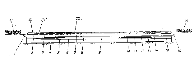
Figure 1 shows a plan view of a horizontally oriented plant
for chemical nickel plating. In this diagram, the reference
numbers 1 to 16 refer to the various stations or modules: 1,
loading module; 2, hot degreasing module; 3, static rinse
module; 4, running rinse module; 5, etching module; 6, static
rinse module; 7, running rinse module; 8, pre-immersion
~001269
module; 9, chemical nickel plating module; 10, static rinse
module; 11, static rinse module; 12, running rinse module;
13, post-immersion module; 14, hot rinse module; 15, drying
module; 16, unloading module.
In the present embodiment, wire clips or bails 17 for
producing the closing and retaining devices for
correspondence files are to be nickel plated by a chemical
process. Such a clip is shown at enlarged scale in figure 3.
A series 18 of clips, arranged one after the other, enters a
conveyor trough 19 from a wire-bending machine (not shown
herein) and passes through the plant loading station 1 in the
direction indicated by the arrow 20. In this example, there
are five tracks with a corresponding number of conveyor belts
or chains to which the bails 17 are passed, so that five such
tracks pass through the plant. Removal is effected after
processing has been completed, and takes place in the
direction indicated by the arrow 21.
In Figure 2, the continuous line 22 indicates the path of the
bulky elements, whereas the broken line 23 shows the level of
liquid in the baths or the liquid in the individual modules 2
to 15. From this it can be seen that the path 23 of the
goods within the modules runs beneath the surface 23 of the
liquids. In contrast thereto, when moving from one module or
liquid basin to the next, as at 22', the goods pass upwards
to a point above the surface of the liquid, across the
partition, and then into the next module or liquid basin,
wherein they are once again moved beneath the surface 23 of
the liquid, where they are processed.
The embodiment illustrated in figures 4 and 5 shows two
modules or liquid basins 25, 26, with the liquid baths 27,
28, that are adjacent to each other; as a rule, the baths
differ from each other. The adjacent walls 29 of these two
liquid basins form the partition discussed heretofore.
Within each basin, an endless conveyor belt, or else a
g..
Z001269
conveyor chain 30, passes around rollers 31, at least one
roller per bath being driven so as to rotate in the direction
of rotation 33 that is indicated. The arrangement is such
that the conveyor belt or chain 30 only extends above the
surface of the liquid 32 at the beginning or the end of the
liquid basin so that it can pass the bulky parts 17 to the
next subsequent conveyor belt or conveyor chain 30 (here,
that of the liquid basin 26) in the area above the separating
wall 29. Any residue from the bath 27 that may still be
adhering to the closing parts 17 drip off the closing parts
27 after they have left the bath, so that for all practical
purposes, no bath liquid 27 is carried over into the bath
liquid 28.
The cross-section in figure 5 shows guides 35 on the long
side walls 34' of the liquid basin 25, these preferably being
of smooth, slippery plastic. On their side that is closest
to the bath, these guides in corporate guide grooves 36 in
which the ends of the cross bars 38, which project outwards
from the conveyor belt or chain, form a sliding fit. The
particular conveyor belt or chain 30 is guided downwards and
into the bath by this means from the junction points
(separating walls) of the two modules or liquid basins. The
parts 17 lie loosely on the conveyor belt, or are picked up
by these. The bars 38 are secured to a belt 39, or pass
through this. On the upper surface of the belt 39 there are
projections 40, and the parts 17 come to rest against these.
The projections are matched to the shape of the parts that
are to be electroplated. This cross-section also shows the
five tracks already discussed in conjunction with figure 1.
Each module incorporates such a conveyor belt or chain (this
also applies to the other embodiments). The conveyor belts
can also be made up of individual sections that are connected
to each other.
Z001269
In the example shown in figures 4 and 5 both the upper run 40
and the lower run 41 of the conveyor belt or chain 30 lie in
the particular bath, with the exception of those sections
that are located close to the particular partition wall. If
required, the bars 38 can be installed on the upper side of
the belt 39, so that they become the drivers for the moving
the closing parts 17 in place of the projections 40.
In the example shown in figures 6 and 7 the conveyor belt or
chain, in this instance a notched belt 42 with teeth 43, is
located above the surface of the liquid 32 and is turned by
the drive roller 31 in the direction indicated by the arrow
33.
Figure 6 shows the exit end of the associated liquid basin
25. The entrance end of the liquid basin (not shown herein)
is configured in the same way. Contact surfaces, here in the
form of guides 44, 45, are provided to convey the parts 17
from the entrance to the exit end of the basin 25. The guide
44, which extends horizontally, merges at the exit end into a
rising guide 45 that emerges from the liquid 32 into the
transfer point 47 to the next basin 47. A similar, inclined
trough is located at the entrance side to this basin. This
leads from the corresponding transfer area of the separating
wall 29 and is inclined downward as far as the guide 44. The
guide 44 and the lower area of the rising guides are located
beneath the level of the liquid 32. Drivers 46 are attached ~-
to the outside of the notched belt 42 and these are of such a
length that they engage with the parts 17 that are in the
guides 44 and move them to the transfer point 47 that is
located above the separator wall 29. They pass along the
guide 45' that slopes downward into the next basin 26. Thus,
only the drivers 46 of the conveyor belt come into contact
with the liquid, which means that the quantity of liquid that
is picked up from the basin 25 and carried into the basin 26
is further reduced. The belts can also be fitted with driver
cups .
Z001269
Figure 7 shows a possible variation in the configuration of
the guides 44 or the corresponding contact surfaces or cross-
sectional configurations on the bottom 48 of this basin 25.
The embodiment is matched to the cross-section of the parts
17, and these parts can incorporate bent sections 17' that
are oriented outward, as is shown. Here, the guides consists
of a projection 49 that is of rectangular or quadrilateral
section, which extends upwards from the bottom 48 and fits
over the part 17. Between these projections 49 there is a
space 50 that accommodates the bent sections 17'. It is
recommended that the projections 49 and the contact surfaces
51 beneath the spaces 50 be of a plastic that has good slip
properties in order to make it easier to move the parts 17.
Two tracks are shown in this instance. However, a different
number of tracks, for example 5, could be incorporated. The
guides could also be configured differently, e.g., as grooves
or troughs. Also, in this embodiment, a number of conveyor
chains could be used in place of a conveyor belt, and these
would then form tracks with each other.
The transfer points can be fitted with separating devices.
Finally, the embodiment shown in figures 8 to 11 shows chains
52 that are used as conveyor means; these are endless and
circulate in a liquid basin 25 or 26, respectively, the path
corresponding approximately to that shown in figures 4 and 5.
Either guides 35 or 37 as in figure 5, or rollers 53 as shown
in this embodiment, ensure that the chains are guided by the
upper roller in each instance, from the transition point 55
above the separator wall 29 beneath the level of the liquid
32, into the bath 27, so that the parts 17 that are moved
with it are within the liquid within the associated basin for
the greater part of the zone of movement. Here, too, more
than two chains and a corresponding number of tracks can be
provided next to each other. The principle modes of
operation, in particular the transfer, are similar to those
explained in connection with the foregoing examples. Drivers
2001269
54 extend between two associated chains 52, and these can
engage with and move the parts 17 (see figures 9 to 11). The
drivers 54 are U-shaped, with bent sections 54' that are
oriented to the side and attached to the chains 52. There
could be hooks (not shown herein) on the chains in place of
the drivers 54, and these hooks would then pick up the parts
that are to be electroplated. The parts 17 in the form of
these bails can also be moved when upright, and are then
picked up by the hooks. The drivers 54 also perform the
function of keeping the chains apart from each other and
thereby form a circulating conveyor system. Figure 8 shows
that the chains of both liquid basins approach closely enough
to the transition point 55 that at that point the parts 17
are switched from one chain onto the next chain and then
conveyed further through the system.