Note : Les descriptions sont présentées dans la langue officielle dans laquelle elles ont été soumises.
2G~2375
SPRAY GUN WITH DISPOSABLE LIQUID HANDLING PORTION
Technical Field
The present invention relates to air operated
liquid spray guns.
lOBackground
Air operated li~uid spray guns have typically
contained passageways that are difficult to clean except by
passing a solvent through the gun. Such spray guns have
thus not been practical for use to spray liquids such as two
15part epoxies that cure and subsequently can not be removed
by solvents, or liquids that are not easily removed by
solvents, or are only removed by solvents that are extremely
expensive or dangerous to use.
20Disclosure of Invention
The present invention provides a spray gun with a
disposable liquid handling portion that is sufficiently
inexpensive that it can be disposed of after use, thus
allowing a user to spray liquids that can not, or can not
25easily, economically or safely be removed from a
conventional spray gun, which spray gun is particularly
useful for spraying relatively high viscosity liquids such
as those above 10,000 centipoise.
According to the present invention there i~
30provided a liquid spray gun comprising (1) a reusable air
gun portion including a manually engageable handle, having
means defining a through passageway including an inlet
portion adapted to be attached to a source of air under
pressure and an outlet portion, and a manually operable
35valve in the through passageway for controlling the flow air
through the passageway; and (2) a disposable container and
spray nozzle assembly comprising a tube, at least one sheet
of tough flexible material having portions attached together
and to a central sealing portion of the tube to form a bag
like container defining an internal chamber in which liquid
2002375
is contained with an inlet end portion of the tube within the
chamber and an outlet end portion of the tube outside of the
chamber. The assembly also lncludes a nozzle having a li~uid
inlet port connected to the outlet portion of the tube with
the through opening in the tube communicatlng with the liquid
inlet port, an air inlet port releasably coupled to the outlet
portion of the reusable air ~un portion, a spray tip portion
havlng an outlet opening, a through opening communicating
between the outlet opening and the liquid and air inlet ports,
and venturi means for forming a vacuum at the fluid lnlet port
upon movement of air into the air inlet port and out the
outlet opening in the nozzle so that atmospheric pressure will
bias liquid in the chamber into the inlet port to be entrained
in air passing out of the outlet opening of the nozzle.
The chamber defined by the sheet may be undivided,
and the inlet end portion of the tube may extend toward the
end of the chamber opposite its inlet end portion to insure
that most of the liquid within the chamber can be dispensed
through the spray gun. Alternatively, the sheet or sheets
2G forming the chamber can be attached together along one or more
transverse lines of temporary attachment (as is taught in U.S.
Patent No. 2,932,385 to separate the chamber into parts with
the inlet end portion of the tube positioned in one part of
the chamber and disposed generally at a right angle to the
adjacent temporary attachment line and components of the
liquid separated in different parts of the chamber. The
assembly can then include a novel coil comprising a strip
disposed in a plurality of wraps about an a~ls and havlng a
2002375
spring temper biasing the strip to an axially extended
position with successive wraps of the strip materlal having
opposite edge portions overlapping to form a tube like
structure, with an end portlon of the coil positioned around
the inlet end portion of the tube and the coil retained by the
temporary attachment line in one part of the chamber with the
wraps overlying each other. The temporary
- 2a -
~ns~.7-~778
2~2375
--3--
attachment line(s) can then be manually separated to afford
movement of the coil to its axially extended position
extending toward the end of the chamber opposite the tube so
that during spraying it will insure that most of the liquid
5 can be dispensed from the chamber.
As another alternative, the novel coil can be used
when the chamber defined by the sheet is undivided so that
the coil extends toward the end of the chamber opposite the
tube, and the sheet of material can have pleats along lines
lOextending generally at right angles to the axis of the coil
to afford, under the influence of atmospheric pressure as
liquid is dispensed from the chamber, shortening of the
chamber in a direction parallel to the axis by folding of
the sheet of material along the pleats and movement of the
15coils against the bias of the spring temper toward a
position with the coils overlying each other.
Brief Description of Drawing
The present invention will be further described
20with reference to the accompanying drawing wherein like
reference numerals refer to like parts in the several views,
and wherein:
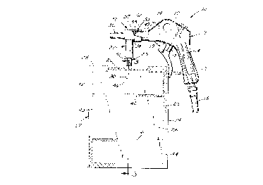
Figure 1 is a side view of a spray gun according
to the present invention attached to a fragment of an air
25supply hose and having parts broken away to show details;
Figure 2 is a fragmentary top view of the spray
gun of Figure 1 showing a reusable air gun portion separated
from a disposable spray nozzle and having parts broken away
to show details;
Figure 3 is a sectional view taken approximately
along line 3-3 of Figure 1;
Figure 4 is a view similar to that of Figure 3 in
which temporary seals have been broken to afford extension
of a novel coil included in the spray gun; and
Figure 5 is an alternate embodiment of a
disposable container and spray nozzle assembly that can be
included in a spray gun according to the present invention.
2C~2375
Detailed Description
Referring now to the drawing, there is shown a
spray gun according to the present invention generally
designated by the reference numeral 10.
AS illustrated in Figures 1, 2, 3 and q, the spray
gun 10 comprises (1) a reusable air gun portion 11 including
a manually engageable handle 12, having means defining a
through passageway 14 including an inlet portion adapted to
be attached as by a threaded coupling and a hose 15 to a
lOsource of air under greater than atmospheric pressure and an
outlet portion 16, and manually operable valve means in the
form of an air valve assembly 17 in the through passageway
14 and manually operable by a trigger 18 pivotably mounted
on the handle 12 at a pin 19 for controlling the flow air
15through the passageway 14; and (2) a disposable container
and spray nozzle assembly 22. The disposable container and
spray nozzle assembly 22 includes a bag like container 27
- comprising a tube 23, and at least one sheet 24 of tough
flexible material having edge portions 25 attached together
20and to a central sealing portion 26 of the tube 23 that has
in transverse section a generally elongated diamond shape to
form the container 27 and define an internal chamber 28 in
which liquid is contained with an inlet end portion 30 of
the tube 23 within the chamber 28 and an outlet end portion
2531 of the tube 23 outside of the chamber 28. Preferably the
tube has an inner diameter of at least 0.63 centimeter to
afford passage of high viscosity liquids such as liquids
having viscosities of 10,000 centipoise or greater. AlSo
included in the assembly 22 is an aspirating nozzle 32
30having a liquid inlet port 33 connected to the outlet end
portion 31 of the tube 23 with the through opening in the
tube 23 communicating with the liquid inlet port 33, an air
inlet port 34 releasably coupled to the outlet portion 16 of
the reusable air gun portion 11, a spray tip portion 36
35having an outlet opening 37, a through passageway 38
communicating with the outlet opening 37 and liquid and air
inlet ports 33 and 34, and means for forming a vacuum at the
Z(~Z3~S
--5--
liquid inlet port 33 upon movement of air into the air inlet
port 34 and out the outlet opening 37 in the spray tip
portion 36 so that atmospheric pressure will bias liquid in
the chamber 28 into the liquid inlet port 33 to be entrained
sin air passing out of the outlet opening 37 in the spray tip
portion 36.
The chamber 28 defined by the sheet 24 could be
undivided, and the inlet end portion 30 of the tube 23 could
be much longer than illustrated and extend toward the end of
the chamber 28 opposite its inlet end portion 30 to insure
that most of the liquid within the chamber 28 can be
dispensed through the spray gun 10. As illustrated,
however, as is particularly useful for spraying liquids
comprising two components that react with each other and
solidify in a short time, opposed portions of the sheet 24
can be attached together along first and second transverse
lines 40 and 41 of temporary attachment as taught in
U.S.Patent No. 2,932,385 to separate the chamber 28 into
first, second and third parts 42, 43, and 44 respectively,
20with one component of the liquid being contained in the
second part 43 of the chamber 28, another component in the
third part 44 of the chamber 28, and the inlet end portion
30 of the tube 23 positioned in the first part 42 of the
chamber 28 and disposed generally at a right angle to the
25temporary attachment lines 40 and 42; and the assembly 22
can include a novel dip tubing means or coil 46 comprising a
strip disposed in a plurality of wraps about an axis and
having a spring temper biasing the strip to an axially
extended position (Figure 4) with successive wrap~ of the
30strip having opposite edge portions overlapping to form a
tube like structure. The end of the innermost wrap of the
coil 46 is attached axially along the inlet end portion 30
of the tube 23 with the axis of the coil 46 generally
aligned with the inlet end portion 30 of the tube 23 and, as
35is illustrated in Figure 3, the coil 46 is retained in the
first part 42 of the chamber 28 with the wraps overlying
each other by the first temporary attachment line 40. The
second temporary attachment line 41 can then be manually
21:~Z375
--6--
separated just prior to spraying to afford mixing the first
and second components of the liquid by kneading the
container 27, and the first temporary attachment line 40 can
them be manually separated to afford movement of the coil 46
sunder the influence of its spring bias to its axially
extended position extending toward the end of the chamber 28
opposite the tube 23 so that during spraying the coil 46
will restrict collapse of the container and insure that most
of the liquid can be sucked from the chamber 28 through the
lOextended coil 46. Preferably the second temporary
attachment line 41 is separated first so that the first and
second components of the liquid can be mixed without the
coil 46 being extended, and then the first temporary
attachment line 40 is separated so that the coil 46 moves to
lSits extended position through the mixed liquid.
The air inlet port 34 is releasably coupled to the
outlet portion 16 of the reusable air gun portion 11 by the
nozzle 32 having a cylindrical socket 49 adapted to receive
a distal part of the cylindrical outlet portion 16 with a
20pin 50 projecting radially of the outlet portion 16 received
in a generally L-shaped groove 52 in the wall defining the
socket 49. Upon insertion of the outlet portion 16 into the
socket 49 the pin 50 moves along an axially extending
portion of the groove 52, whereupon the nozzle 32 and air
25gun portion 11 are rotated about their axes relative to each
other so that the pin moves along a circumferentially
extending portion of the groove 52 having a wall that cams
the end of the outlet portion 16 into sealing engagement
with a rubber gasket 53 in the socket 49 and provides a
30detent at the end of such movement to retain the pin 50 at
the end of the groove 52 until a significant amount of force
is applied to again rotate the nozzle 32 and air qun portion
11 relative to each other to separate them.
The means for forming a vacuum at the liquid inlet
35port 33 upon movement of air into the air inlet port 34 and
out the outlet opening 37 in the spray tip portion 36 so
that atmospheric pressure will bias liquid in the chamber 28
;20~Z3~7~
--7--
into the liquid inlet port 33 to be entrained in air passing
out of the outlet opening 37 in the spray tip portion 36
comprises a venturi structure within the aspirating nozzle
32. The venturi structure is provided by a hollow
5cylindrical tube 56 (e.g., 0.376 centimeter inside diameter
and an outside diameter tapered from 0.467 to 0.3
centimeter) projecting (e.g., 2.14 centimeters) from a
cylindrical disc 57 coaxially received in the inner end of
the socket 49, which disc 57 defines at its center the air
lOinlet port 34 which communicates with and is the same size
as the central opening in the tube 56. The tube 56 project~
centrally into a chamber 58 with which the liquid inlet port
33 communicates, which chamber 58 diverges smoothly and
concentrically to the outlet opening 37 (e.g., a chamber 58
15diverging from a diameter of 0.91 centimeter around the base
of the tube 56 to a diameter of 0.52 centimeter at the
outlet opening 37 over a length of 4.13 centimeters) in the
spray tip portion 36 of the nozzle 32.
The sheet 24 of tough flexible material from which
20the container 27 is made is preferably of a laminated
material including layers of polyester, aluminum and low
density polyethylene such as that material commercially
available from Ludlow Corporation, Lombard, Illinois, and
identified as a laminate of "48 gauge polyester x 0.8 #/1000
25sq. ft. W-01-978 thermosetting adhesive x 0.00035 aluminum
type 1145 x 0.8 #/1000 sq. ft. W-01-978 thermosetting
adhesive x 0.003 linear low density, polyethylene (1151B)
(0.910-0.925)n. The low density polyethylene layer is fused
together to form the edge portions 25 and to the central
30portion 26 of the tube (which is made of Delrin (t.m.)) to
form the chamber 28, and the low density polyethylene layer
is heat sealed to both surfaces of a layer 61 of thin porous
paper coated on both surfaces with a thin continuous layer
of polyethylene to form the temporary transverse lines 40
35and 41 that separate the chamber 28 into the parts 42, 43,
and 44, and are manually separable to afford mixing of the
liquid and extension of the coil 46.
20~2375
--8--
The coil 46 is preferably made from a strip of
polyester that is 1.1 inches wide, 24 inches long, and 0.01
inch thick. The strip is wound into a coil having an inside
diameter of 0.38 inch and an outside diameter of 0.7 inch,
5 axially extended to an overall length of about 10.5 inch and
heat set at about 115 degrees centigrade (240 degrees
Fahrenheit) for about 4 minutes so that it has a spring
temper biasing it to that extended form.
The reusable air gun portion 11 can be made by
cutting the end portion including the dip tube from a
commercially available spray gun available from Minnesota
Mining and Manufacturing Company, St. Paul, Minnesota under
the trade designation "sody Schutz Applicator Gun", Part No.
08997.
Preferably the spray gun 10 also includes means
for relieving pressure that could develop in the liquid
inlet port 33 should the outlet opening in the spray tip
portion become plugged. That means for relieving pressure
may be in the form of a frictional connection between the
20outlet end portion 31 of the tube and the liquid inlet port
33 of the nozzle 32 that will separate at a predetermined
pressure that is less than a pressure required to rupture
the container 27, or a diaphragm (not shown) in the nozzle
32 or container 27 that will rupture at such a predetermined
25pressure.
A container 27 of the preferred type described
above had part 44 of the chamber 28 filled with 32
milliliters of "Parte A" of a 2 part urethane automobile
coating (i.e., the coating being formed from 08660 Parte A
30and 08660 Parte B, commercially available from 3M Italia
SPA, P.O. Box 10411-10412, 20110 Milano, Italy), and had
part 43 of the chamber 28 filled with 180 milliliters of
"Parte B~ of the coating. The second temporary seal line 41
was then broken, and the container 27 was kneaded for about
3530 seconds to mix the parts of the coating together. The
first temporary seal line 40 was then broken, which allowed
the coil 46 to move under the influence of its spring bias
- 9 -
to its axially extended position extending toward the end of
the chamber 28 opposite the tube 23. Using the nozzle 32
and air gun portion 11 described above attached to a source
of air pressure of 4 bars (60 pounds per square inch), the
smixed liquid in the chamber 28 was then sprayed onto a
phosphate treated cold rolled steel 4 inch by 12 inch panel
from a distance of 6 to 12 inches away. Visual observations
were made of the cure, delivery rate, completeness of
evacuation of the liquid from the chamber 28, and spraying
characteristics. The coating cured satisfactorily, the
delivery rate was similar to state of the art spraying
methods, there was no spattering during spraying, and about
75 to 80 percent of the liquid was removed from the chamber
28. Also, by varying the distance between the nozzle 32 and
the panel, and/or varying the air pressure to the spray gun
10, different coating textures were achieved.
Figure 5 illustrates an alternate embodiment of a
disposable container and spray nozzle assembly 68 that can
be included in a spray gun according to the present
20invention and comprises a container 69 including a novel
coil 70 having the same structure as the coil 46 described
above, which assembly 68 can be used as an alternative for
the assembly 22 to spray certain types of liquids through an
aspirating nozzle 71 having the same structure as the nozzle
2532 described above. The container 69 has a chamber 72
defined by a sheet 73 that is undivided so that the coil 70
extends toward the end of the chamber 72 opposite a tube 74,
and the sheet 73 of material has pleats 76 along lines
extending generally at right angles to the axis of the coil
3070 to afford, under the influence of atmospheric pressure as
liquid is sucked or dispensed from the chamber 72,
shortening of the chamber 72 in a direction parallel to the
axis by folding of the sheet 73 of material along the pleats
76 and movement of the coil 70 against the bias of its
35spring temper toward a position with the wraps of the coil
70 overlying each other.
2no2375
The present invention has now been descrlbed with
reference to several ernbodiments and modifications thereof.
It will be apparent to those skilled in the art that many
changes can be made in the embodiments and modifications
described without departing from the scope of the present
invention. For example, a coil 46 or 70 of the type
illustrated could be used in a container generally of the type
described in U.S. Patent No. 4,492,313 to provide a container
assembly in which a flexible wall defines a chamber having an
îO axls and an opening along the axis, which wall has pleats
along lines extending generally at right angles to its axis to
afford varying the axial length of the chamber by folding of
the wall along the pleats in the manner of a bellows; means
attached to the wall over the opening and having an inlet
opening communlcating with the chamber adapted for affording
withdrawing liquid from the chamber through the inlet opening;
and the coil with an end portion of the co~l positioned around
the inlet opening and the coil extending toward the end of the
chamber opposite the inlet opening, the length of the tube
like structure formed by the extended coil being variable with
the axial 1ength of the chamber so that the tube like
structure can provide a conduit for liquid from the bottom of
the charnber to the outlet opening. Thus, for example, the
tube like structure provided by the coil could provide a
conduit for liquid in the container to a spray nozzle attached
on top of the container that could be an aspirating nozzle of
the type described above, or a nozzle through which liquid is
pumped by a manually operated pump attached on the top of the
-- 10 --
200~375
container. Thus the scope of the present invention should not
be limited to the structures described in this application,
but only by structures described by the la~guage of the claims
and the equivalents of those structures.
- lOa -