Note : Les descriptions sont présentées dans la langue officielle dans laquelle elles ont été soumises.
XO~ 3 ,
!
ANTILOCX BRAKE CONTROLLER I~PROVEMENTS
:. :
~ACXGROUND OF THE INVENTION
1. Field of the Invention
This invention relates to an electronically
controlled anti-locX braking system (A~S) for a motor
vehicle.
2. Descr$ption o~ Related Art
El~ctronically controlled ABS systems ,~re known
i in which a microprooessor i~ used to control relea6e
of the brakes of a ~otor vehicle in response to a
determination by the microprocessor that the brakes
have locked or are approaching a locked up condition.
When 3uch a determination is made, a ~ignal from the
controller typically actuates an elec~ro-magnetic
brake release/ e.g., a solenoid controlled valve ln
the brake system.
A determination of wheel locXlng generally
requires meas~urement of actual wheel speed or
deceleration, and a determination that the actual
wheel speed or deceleration ~5 respectively lower than
or greater than a predetermined wheel ~peed or
deceleration limit indicative of an incipient wheel-
lock situation. It is also possible to make the
determination based on a measurement of actual G-
.
'
, - '":
~t' $~
.
~()o~3rj~a
force and co~parison with a wheel-speed derived G-
force curve.
Such syste~ are all subject to the common
problems of spurious determinations resulting from
controller malfunction, and malfunctions in the
electro-magnetic brake release. Improper functioning
of the ABS can, of course, lead to disactrous
consequences, either from failure to release the
brakes when the wheels are locked, or from an
unintended brake release when braking is required.
As a result, it has been proposed to provide
fail-safe circuit~ for the main controller, and to
provide feedback from the brake release to the
controller in order to permit the controller to
monitor the brake release. Such proposals have not
proven to be adeguate, given the life-threatening
potential of even one malfunction.
A typical "fail-safe" ABS is shown in patent no.
4,700,304, to Byrne et al. In Byrne et al, an analog
1 20 fail-safe circuit is provided which includes a fuse in
¦ serie6 with the drive circuits of an electro-magnetic
brake release. When the fuse is blown, the brake
release is prevented from operating.
The central A~S controller is a microprocessor
which 6ends out periodic pulses to the fail-safe
circuit which disable6 the fail-safe means from
blowing the fuse. The fail-safe circuit of Byrne et
al. cannot act independently of the microproce6sor,
being completely dependent on proper output by the
microprocessor of the periodic pulse6. If no puloe is
received within a predetermined period of time, the
fuse automatically blows, but as long as the pulses
are received, the fail-safe means i5 disabled.
An analog system of the type shown in ~yrne et
al., in addition to being subject to such
~` microprocessor internal errors as, for example,
misreading of a brake-release feedback signal, suffers
., ~ ~.
Z00~5~8 1 ~
from an unacceptably slow respon~e time. As a result,
it has been proposed to substitute a microprocessor
for the conventional analog fail-safe circuit.
An example of a sy6tem which uses separate
microprocessors for detecting malfunctions is
disclosed in patent no. 4,709,341 to Matsuda. In
Matsuda, identical microprocessors are provided which
monitor each other in addition to performing as ABS
controllers for respective wheels of the motor
vehicle. Due to costs, such a system i3 suitable only
where separate controllers are required, and in
addition suffers from the drawback that it is subject
to systematic errors from such sources as radio
frequency interference and power supply fluctuations
which affect all of the identical microprocessors of
Matsuda in exactly the same way due to their identical
structure and functions.
SUMMARY OF ~HE INVENTION
It is an ob~ect of the invention to overcome the
~ drawbacks of the prior art by providing an ABS fail-
¦ safe controllar which includes a fail-snfe
m~croprocessor independent of the main controller.
~he fail-safe microproceesor of the subject invention
is capable of disabling a brake-release meanB either
upon detection of main controller malfunction or upon
detection of brake-release failure.
~ The fail-safe ~icroprocessor le programm~d to
j read periodic pulsee from the main controller, the
i~ 30 pulses being lndicative o~ proper main controller
operation, and to prevent the brake-release from
~ operating when the pulse6 are not detected.
3 Furthermore, even when pulses are detected,
indicating proper main controller operation, the fail-
~ 35 safe microprocessor will still disable the brake-
i~ release upon detecting, independently of the main
microprocessor, that the brake-release ~s
'
`~ 200~7~
malfunctioning. Separate feedback lines are provided
to permit both the main controller and the fail-safe
S microprocessor to monitor the brake-release.
The fail-safe microprocessor is
advantageously a one-bit microprocessor programmed to
monitor several different brake-release means without
the need for multiple analog fail-safe circuits.
Control of the brake-release means is
preferably implemented via a switch in the drive
circuit of the brake-release and responsive to pulses
output by the one-bit microprocessor, failure of
which automatically opens a switch.
An especially advantageous embodiment of
the one-bit microprocessor includes a timer for
independently monitoring the solenoid on-time of the
brake-release, the microprocessor being capable of
shutting down the brake release if the on-time
exceeds a predetermined value.
In accordance with an embodiment of the
invention, in an anti-lock brake system for a motor
vehicle, the system including apparatus for sensing
the rate of rotation of a member whose rate of
rotation is indicative of the speed of a wheel of the
vehicle; apparatus for generating a wheel speed
signal indicative of the rate of rotation; a main
control circuit having apparatus for determining an
incipient wheel-lock condition based on the wheel
speed signal and apparatus for generating a brake
release signal upon determining the incipient wheel-
lock condition; and apparatus for releasing a brake
in response to the brake-force release signal, the
improvement comprised of a main microprocessor; a
fail-safe microprocessor of a different type;
20~78
~ ... . .
4a
apparatus for connecting the main microprocessor to
the brake-release apparatus such that the main
microprocessor monitors whether the brake-releasing
apparatus has released the brake in response to the
brake-force release signal; and apparatus for
electrically connecting the fail-safe microprocessor
and main microprocessor such that the fail-safe
microprocessor monitors the main microprocessor; the
fail-safe microprocessor including apparatus for
preventing release of the brake by the brake-release
apparatus upon either a determination that the brake-
release apparatus is functioning improperly or a
determination that the main microprocessor is
functioning improperly; whereby the fail-safe
microprocessor is capable of disabling the brake-
release independently of the main microprocessor.
"`-,'~.
BRIEF DESCRIPTION OF THE DRAWINGS
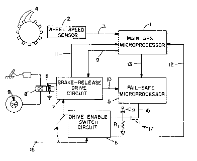
Figure 1 is a schematic view of a preferred
embodiment of the invention. ~ :
Figures 2 and 3 illustrate the operation of
the fail-safe microprocessor of the preferred
embodiment. :
DESCRIPTION OF THE PREFERRED EMBODIMENT ::
Fig~re 1 shows the main elements of an
exemplary ABS fail-safe system according to the ; :
present invention. In Figure 1, controller 1 is a --
30 control circuit or control microprocessor determining ` .
an incipient wheel-lock condition in response to an
input from wheel speed sensor 2 along line 3.
The wheel speed sensor 2 is responsive to
the passage of magnetic elements 4 which rotate with,
for example, the differential gearing of a motor
vehicle axle (not shown), and thus provides a signal ~ :
indicative of the speed of the wheel or wheels
' : ~
B - :~
~0(~;~5~
connected to tha ~xle. An esp~clally advantageou~
6ensor o~ thi~ type is ~hown in patent no. 4,724,935
to Roper, incorporated herein by refsrence, although
any 6ensor arrangement whlch provides ~ ~lgn~l !
indicative of wheel ~peed or changes in wheel ~peed
could be used in connection with the preferred
embodiment of this invention.
The controller 1 may, for example, be a
microprocessor of the type ~hown in the above-
mentioned patent to Roper, incorporated by reference !
herein, which operates by selecting, according to
input from the wheel speed sensor, an appropriate
deceleration reference curve. The selected reference
curve, when crossed by an actual wheel speed curve,
indicate an incipient wheel lock condition, and the
controller subsequently provides a signal which causes
braking pressure to be reduced, releasing the brakes.
The main controller 1 of the pre~erred
embodiment, however, need not be limited to the
particular controller described above. The ~pecifics
of incipient wheel lock determination form no part of p
the instant invention. The preferred failsafe system ~-
may be applied to a wide variety of main ABS
controllers. ~ -~
Upon determlnatlon of an incipient wheel lock
condition, main controller 1 provides a si~nal ~long
line 9 to brake-release drive circuit 7 which cau6e
drive circuit 7 to actuate solenoid 8, opening a valve
8' for modulating the brakes B o the vehicle ~not
shown).
In order to ensure that ~hort circuitsi between
the vehicle frame and the ~olenoid do not affect the
controller, the 601enoid i6 switched on it3 high
voltage side. For example, one side of the soleno~d
may be pulled high to 12 volts when turned on by the
controller. No circuit malfunction occur6 i~ this
lead ~horts to the frame. If the high side solenoid
-~:
'. . ~
zon~s78
lead shorts to the frame, the control system fails
safe and does not turn the solenold on, preventing
damage to the controller.
When the main ABS microprocessor 1 is operating
properly 7 it provides a periodic signal along status
line 13 to a fail-safe microprocessor 5. The periodic ! -:
signal may be in the form of a pulse automatically
generated once every cycle of a main control loop, or
it may be generated, for example, in response to an
internal microprocessor diagnostic routine.
Fail-safe microprocessor 5 is for example a one-
bit microprocessor different in type from the main
microprocessor. This will lessen the possibility of
systematic errors in both the main microprocessor and
the fail-safe microprocessor. -
Fail-safe microprocessor 5 outputs a signal along
line 15 through AC coupling integrator 17, which
enables brake-drive enable switch 6 when no
malfunction is detected by the fail-safe
microprocessor. The AC coupling may include
capacitors C~ and C2, and resistor R~, thus serving to
integrate a pulsed output on line 15, which can then
be level detected by switch 6.
Failure to receive a periodic signal along status
line 13 within a predetermined time period is
interpreted by fail-safe microprocessor 5 as a
malfunction in the main microprocessor 1, and the
fail-safe microprocessor consequently ceases to enable
brake-drive enable switch 6, causing the brake-release
to shut down.
In addition to lines 13 and 15, which
respectively serve to carry signals indicative of main
controller health and to carry an independently
generated fail-safe signal for controlling drive
enable switch circuit 6, lines 11, 12, and 10 are
provided to provide feedback to the main
microprocess~ and the drive enable switch circuit
~ .
Z00~7f~ ~
regarding operation of drive enable switch circuit 6
and brake-release drive circuit 7.
Feedback lines 11 and 12 are connected,
respectively, between main controller 1 and brake-
release drive circuit 7, and -between main
microprocessor 1 and drive enable switch circuit 6.
Feedback line 10 is connected between a logic input of
fail-safe microprocessor 5 and brake release drive
circuit 7. In addition, both main controller 1 and ~1
feed-back microprocessor 5 are capable of monitoring
additional brake-release solenoid drive circuits,
.. . ....
e.g., Por each axle of a truck.
Referring to Figures 2 and 3, the one-bit
microprocessor performs two primary monitoring
functions. The first, indicated by reference numeral
1000, is the main controller monitoring function
described above. As indicated by functlon step 1001,
if toggling of status line 13 by the main
microprocessor fails, then the failsafe microprocessor
disables the drive enable switch circuit.
The second function of the fail-safe
microprocessor 5, indicated generally by reference
numeral 1002, is to monltor the on-time output o~ the ~;
i~; brake-release drive circuit. -~
25The failsafe microprocessor monitors the on-time
of the output of the brake-release drive circult for
a predetermined time interval, e.g., 200 ms, as ;~
~, indicated by steps 1004 and 1005 of the on-time
algorithm, shown in Figure 3. If the solenoid which
30is connected to the output of the brake release drive
circuit is still on after the predetermined time
interval, then the fail-safe microprocessor disables
the drive enable switch circuit to disable the brake
release.
35The one-bit microprocessor of the preferred i~
embodiment uses a 200 ms timer because at slow vehicle
;~ speeds, under appropriate conditions, the main
~ ''i;~ >~}"~
~oo~7~
microprocessor algorithm does not require a longer on-
time, and therefore a solenoid on-time of longer than
200 ms would indicate a malfunction and result ln an
unnecessarily long and possibly hazardous brake-
release.
However, under certain circumstances, and
especially at higher speeds, longer on-times may be
needed. This is accomplished in a very simple manner
while maintaining the 200 ms fail-safe capability, by
pulsing or turning off the brake-release solenoid for
short periods to reset the 200 ms interval timer.
~nder 51 ippery road conditions at hi~h speeds, the
main microprocessor may be programmed to require
brake-releases of as long as 3 seconds, in which case
~5 the solenoid might, by way of example, be ~omentarily
pulsed off every 60 ms to reset the 200 ms interval
timer. Such momentary pulsing would not affect the
brake release performance of the solenoid.
Thus, the fail-safe controller of the preferred
embodiment is responsive to both failure of the main
microprocessor and to malfunctions in the solenoid
which are independently detected, to shut down the
brake-release function of the anti-lock braking system
whenever there is a malfunction that could affect
braking performance.
It i6 to be understood that the invention is not
to be restricted to the details of the specific
embodiment described, but rather that the scope of the
invention should be limited only by the appended
claims.
-~
~ ,,
'' ~.
'.
-
i3 s . ; ~
~! ' i ' . ~ .. " ~