Sélection de la langue

Search

Sommaire du brevet 2007459 

Énoncé de désistement de responsabilité concernant l'information provenant de tiers

Une partie des informations de ce site Web a été fournie par des sources externes. Le gouvernement du Canada n'assume aucune responsabilité concernant la précision, l'actualité ou la fiabilité des informations fournies par les sources externes. Les utilisateurs qui désirent employer cette information devraient consulter directement la source des informations. Le contenu fourni par les sources externes n'est pas assujetti aux exigences sur les langues officielles, la protection des renseignements personnels et l'accessibilité.

Disponibilité de l'Abrégé et des Revendications

L'apparition de différences dans le texte et l'image des Revendications et de l'Abrégé dépend du moment auquel le document est publié. Les textes des Revendications et de l'Abrégé sont affichés :

  • lorsque la demande peut être examinée par le public;
  • lorsque le brevet est émis (délivrance).
(12) Demande de brevet: (11) CA 2007459
(54) Titre français: MONTAGE PERFECTIONNE DE CHICANES POUR INCINERATEUR ROTATIF
(54) Titre anglais: WEB FOR ROTARY COMBUSTOR
Statut: Réputée abandonnée et au-delà du délai pour le rétablissement - en attente de la réponse à l’avis de communication rejetée
Données bibliographiques
(51) Classification internationale des brevets (CIB):
  • F23G 05/20 (2006.01)
  • F23M 05/08 (2006.01)
(72) Inventeurs :
  • ETTEHADIEH, BOZORG (Etats-Unis d'Amérique)
(73) Titulaires :
  • WESTINGHOUSE ELECTRIC CORPORATION
(71) Demandeurs :
  • WESTINGHOUSE ELECTRIC CORPORATION (Etats-Unis d'Amérique)
(74) Agent: SMART & BIGGAR LP
(74) Co-agent:
(45) Délivré:
(22) Date de dépôt: 1990-01-10
(41) Mise à la disponibilité du public: 1990-07-27
Licence disponible: S.O.
Cédé au domaine public: S.O.
(25) Langue des documents déposés: Anglais

Traité de coopération en matière de brevets (PCT): Non

(30) Données de priorité de la demande:
Numéro de la demande Pays / territoire Date
302,491 (Etats-Unis d'Amérique) 1989-01-27

Abrégés

Abrégé anglais


ABSTRACT OF THE DISCLOSURE
An inclined combustion barrel for a rotary
combustor utilized to burn municipal solid waste wherein
the combustion barrel is formed from a plurality of paral-
lel cooling pipes disposed in a circular array with a
plurality of spaced apart flat plates disposed between
adjacent cooling pipes in descending order with overlapping
ends and side margins welded to the cooling pipes to form a
web between the cooling pipes which improves influent air
flow and extends the life of the web.

Revendications

Note : Les revendications sont présentées dans la langue officielle dans laquelle elles ont été soumises.


5.
utilized in a single zone and that angles other than those
shown could be used in the zones. One advantage of provid-
ing angles less than 6° is that smaller angles will
position the plates 51 so that when disposed in the incin-
erator 1 they will slope downwardly and prevent melted
aluminum from entering the wind box 21.
The disposition of the flat plates 51 between the
cooling pipes 11 as set forth herein advantageously im-
proves the heat transfer to the plates by providing more
efficient convective cooling of the plates 51 as influent
air is forced to flow over the upper and lower surfaces.
This arrangement also positions a portion of the plates 51
so that portions of the plates 51 are not in contact with
the burning waste to provide better heat transfer from the
portions that are in contact with the burning waste as more
heat will be conducted to both the influent combustion air
and to the cooling pipes 11. The boundary layer of influ-
ent combustion air flowing over both sides of the plates 51
will maintain an oxidizing atmosphere encompassing the
plates 51 eliminating the alternating exposure to reducing
and oxidizing conditions, thus reducing the erosion and
wastage of the plates 51 and improving the distribution of
influent underfire combustion air to the combustion portion
15 of the rotary combustor 9 as the combustion air enters
the combustor barrel 9 close to horizontally so as not to
have to partially support the fuel bed as is required with
holes punched in the web. Also the individual plates 51
can be removed and changed without disturbing neighboring
plates 51 improving the maintenance and replacement
thereof.
While the preferred embodiments described herein
set forth the best mode to practice this invention present-
ly contemplated by the inventor, numerous modifications and
adaptations of this invention will be apparent to others
skilled in the art. Therefore, the embodiments are to be
considered as illustrative and exemplary and it is under-
stood that numerous modifications and adaptations of the

invention as described in the claims will be apparent to
those skilled in the art. Thus, the claims are intended to
cover such modifications and adaptations as they are
considered to be within the spirit and scope of this
invention.

What is claimed is:
1. A rotary combustor utilized to burn municipal
solid waste comprising a plurality of spaced apart, paral-
lel cooling pipes disposed in a circular array to form a
generally cylindrical combustor barrel, said barrel being
disposed for rotation on an inclined axis so that the inlet
end of the barrel is above the outlet end and a plurality
of generally flat plates being disposed between adjacent
cooling pipes, the plates being disposed generally parallel
to each other in descending order from the inlet to the
outlet end of the combustor barrel with side margins of the
plates welded to the pipes, with end margins overlapping a
distance L and with a space D extending between adjacent
plates to allow combustion air to flow therethrough.
2. The rotary combustor of claim 1, wherein the
ratio of L over D is greater than 1.
3. The rotary combustor of claim 1, wherein the
ratio of L over D is generally in the range of 4.
4. The rotary combustor of claim 1, wherein the
plates are disposed at an angle with respect to the axis of
the contiguous pipes and said angle is generally in the
range of the angle that the rotary combustor is inclined.
5. The rotary combustor of claim 1, wherein the
plates are disposed at an angle with respect to the axis of
the contiguous pipes, the angle of the plates varying in
different portions of the combustion barrel.
6. The rotary combustor of claim 1, wherein the
plates in at least one portion of the combustor are

disposed at an angle with respect to the axis of the
contiguous pipes and said angle is slightly less than the
angle at which the rotary combustor is inclined.
7. The rotary combustor of claim 1, wherein the
plates in at least a portion of the plates adjacent the
outlet end of the combustion barrel are disposed at an
angle with respect to the axis of the contiguous pipes and
said angle is greater than the angle at which the rotary
combustor is inclined.
8. The rotary combustor of claim 1, wherein the
axis of rotation of the combustor is inclined about 6° and
the plates are disposed at an angle with respect to the
contiguous pipes generally in the range of 6°.

Description

Note : Les descriptions sont présentées dans la langue officielle dans laquelle elles ont été soumises.

ZC~7~59 ` ::
:.
~ " `
... ,~`
` '
.~
" . .
1 55,027 ~- -
IMPROVED WEB FOR ROTARY COMBUSTOR ~
: ;,.:
BACKGROUND OF THE INVENTION
~ he invention relates to a rotary combustor for
burning municipal so~id waste and more particularly to an
improvement in the web between cooling pipes forming the
S combustor.
Webs disposed between cooling pipes o rotary
combustors burning municipal solid waste are sub;ected to
severe operating conditions, high operating tempsrature~,
erosive and corrosive element~ in the municipal waste and a
~as environment which switches back and forth between being
oxidizing and reducing atmosphares resulting in thinning
or wasting of the webs. Making the webs thicker only delays
replacement and reducing the space between cooling pipes to
improve heat transer causes other problems in the combus-
tion of the waste.
U. S. Patent 4,724,778 describes a rotary combus~tor in which municipal solid wa~te is burned in a gas
porous cylinder, having a sectioned and compartmented wind
box permitting selective delivery of air through the
burning waste, above the burning waste, at the start of the
burning process and after burning has been well initiated.
However the gas porous w~bs which connect the cooling pipes
to form the rotary combustor experience metal wastage and
thinning resulting in increased maintenance cost and plant
a1ailab1lity lo~ses.
': '
.

~:Q(~5~
2 55,027
SUMMARY OF THE INVENTION
Among the objects of the invention may be noted
the provision of web members, which will provide more
efficient heat dissipation, improve the~ influent combustion
air flow and stand up to the environment of burning munici-
pal solid waste.
In general, a rotary combustor, when made in
accordance with this invention, compr:ises a plurality of
spaced apart, paral~el cooling pipes disposed in a circu-
lar array to form a generally cylindrical combustor barrel.The barrel is disposed for rotation on an inclined axis so
that the inlet end of the barrel is above the outlet end
and a plurality of generally flat plates are disposed
between adjacent cooling pipes to form the barrel. The
plates are disposed generally parallel to each o~her in
descending order from the inlet to the outlet end of the
combustor barrel with side margins of the plates welded to
the pipes, with end margins overlapping a distance L and
with a space D extending between adjacent plates to allow
combustion air to flow therethrough. The plates are so
disposed that the ratio of L/D is greater than 1 and
preferably in the range of 4 to improve influent air flow
and the life of the plates. The angular disposition of the
plates is also varied to provide the optimum influent air
flow to each portion of the rotary combustor.
BRIEF DESCRIPTION OF THE DRAWINGS-
The invention as set forth in the claims will
become more apparent by reading the following detailed
description in conjunction with the accompanying drawings,
wherein like reference numerals refer to like parts
throughout the drawings and in which:
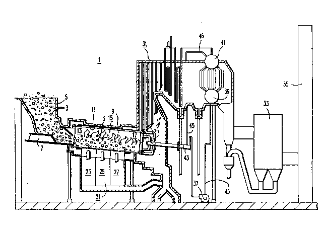
Figure 1 is a schematic view of an incinerator
having a rotary combustor made in accordance with this
invention; .
Figure 2 is a partial sectional view of the
rotary combustor; and
.
'
, ~ ., ., ;.

~7~ss ,.
3 55,027
Figure 3 is an enlar~ed partial sectional view of
a portion of the rotary combustor.
DESCRIPTION OF THE PREFERRED EMBODIMENT
Referring now to the drawings in detail and in
particular to fiqure 1 there is shown an incinerator 1 for
burning municipal solid waste 3, which is fed through a
hopper 5 to a ram 7. The ram 7 pushes discrete amounts of
the waste 3 into a rotary combustor or combustion barrel 9,
wherein the waste 3 is burned. The combustion barrel 9 is
formed from a plurality of generally parallel cooling pipes
11 disposed in a circular array to form a generally cylin-
drical barrel 9. The cylindrical combustion barrel 9 is
divided into an inlet or drying portion 13 adjacent the
hopper 5, an intermediate or combustion portion 15 and an
outlet or burn out portion 17. The combustion barrel 9 is
disposed for rotation on an inclined axis l9 forming an
angle C with a horizontal line so that an inlet end 13
thereof is disposed above an outlet end 17 thereof. A wind
box 21 is disposed to supply combustion air to the combus-
tion barrel 9. The wind box 21 i8 divided in to an inletportion 23, from which the air is supplied to an inlet or
drying portion 13 of the combustor barrel 9, to dry the
waste 3; an intermediate portion 25, from which combustion
air is supplied to the combustion portion 15 of the combus-
tor barrel 9, to devolatilize and burn the waste 3; and anoutlet portion 27, from which combustion air is supplied to
the burnout portion 17 of the combustion barrel 9, to burn
the combustible solids and to burn CO and any other combus-
tible gases. Each portion of the wind box 21 is further
divided into underfire and overfire portions, each portion
having separate controls so that the underfire air and
overfire air can be separately controlled in each portion
o the combustion barrel 9.
Exhaust gases from the rotary combustor barrel 9
flow through a waste heat boiler 31, a ~ilter 33 such as an
electrostatic precipitator or other filtering means and to
a stack 35 from which they are exhausted to the atmosphere.
. ~ .

7~5~
4 5S,027
The cooling pipes 11 making up the rotary combus-
tion barrel 9 are supplied with cooling fluid from a
circulating pump 37, which takes it suction from a water
drum 39 in the waste heat boiler 31 and returns the heated
cooling fluid to a steam drum 41 disposed at the top of the
waste heat boiler 31 via a rotary joint 43 and associated
piping 45.
As shown in Figure 2 and 3 the cooling pipes 11
are spaced apart and a plurality of generally flat plates
51 are disposed between adjacent cooling pipe 11 to form a
web. The plates 51 are disposed generally parallel to each
other in descending order from the inlet end of the combus-
tion barrel 9 to the outlet end thereof. Side maryins of
the plates 51 are welded to the cooling pipes 11 and end
margins of the plates 51 overlap a di.stance L with a space
D extending between adjacent plates 51. The spacing and
location of the plates 51 with respect to one another may
vary from one end of the rotary combustor 9 to the other,
however, in order to provide good penetration o the
Z0 combustion air into the waste 3 and combustor 9 the ratio
of L/D should be greater than 1 and preferably in the
general range of 4. The axis 19 of the rotary combustor 9
is tilted downwardly forming an angle C with a horizontal
line, which angle is generally 6. As indicated in figure
2 the plates 51 are disposed at various angles I, M and 0
with respect to the cooling pipes 11. The angle I is
generally less than 6, while the angle M is generally 6,
positioning the plates in the burning portion of the
combustor barrel 9 generally horizontally. The platec 51
in the burnout portion 17 of the combustor barrel 9 form an
angle 0 which i5 more than 6, in order to provide better
penetration of combustion air into this zone and the
quantity of overfire air suppLied to this zone is prefera-
bly more than the quantity of underfire air supplied to
this zone to minimize the quantity of C0 in the exhaust
gases. While the angles shown are preferred for a particu-
lar zone it is understood that multiple angles may be
,. ,:, ~

Dessin représentatif
Une figure unique qui représente un dessin illustrant l'invention.
États administratifs

2024-08-01 : Dans le cadre de la transition vers les Brevets de nouvelle génération (BNG), la base de données sur les brevets canadiens (BDBC) contient désormais un Historique d'événement plus détaillé, qui reproduit le Journal des événements de notre nouvelle solution interne.

Veuillez noter que les événements débutant par « Inactive : » se réfèrent à des événements qui ne sont plus utilisés dans notre nouvelle solution interne.

Pour une meilleure compréhension de l'état de la demande ou brevet qui figure sur cette page, la rubrique Mise en garde , et les descriptions de Brevet , Historique d'événement , Taxes périodiques et Historique des paiements devraient être consultées.

Historique d'événement

Description Date
Inactive : CIB de MCD 2006-03-11
Inactive : Abandon.-RE+surtaxe impayées-Corr envoyée 1997-01-10
Inactive : Demande ad hoc documentée 1997-01-10
Demande non rétablie avant l'échéance 1993-07-10
Le délai pour l'annulation est expiré 1993-07-10
Inactive : Demande ad hoc documentée 1993-01-11
Réputée abandonnée - omission de répondre à un avis sur les taxes pour le maintien en état 1993-01-11
Demande publiée (accessible au public) 1990-07-27

Historique d'abandonnement

Date d'abandonnement Raison Date de rétablissement
1993-01-11
Titulaires au dossier

Les titulaires actuels et antérieures au dossier sont affichés en ordre alphabétique.

Titulaires actuels au dossier
WESTINGHOUSE ELECTRIC CORPORATION
Titulaires antérieures au dossier
BOZORG ETTEHADIEH
Les propriétaires antérieurs qui ne figurent pas dans la liste des « Propriétaires au dossier » apparaîtront dans d'autres documents au dossier.
Documents

Pour visionner les fichiers sélectionnés, entrer le code reCAPTCHA :


Pour visualiser une image, cliquer sur un lien dans la colonne description du document. Pour télécharger l'image (les images), cliquer l'une ou plusieurs cases à cocher dans la première colonne et ensuite cliquer sur le bouton "Télécharger sélection en format PDF (archive Zip)" ou le bouton "Télécharger sélection (en un fichier PDF fusionné)".

Liste des documents de brevet publiés et non publiés sur la BDBC .

Si vous avez des difficultés à accéder au contenu, veuillez communiquer avec le Centre de services à la clientèle au 1-866-997-1936, ou envoyer un courriel au Centre de service à la clientèle de l'OPIC.


Description du
Document 
Date
(aaaa-mm-jj) 
Nombre de pages   Taille de l'image (Ko) 
Abrégé 1990-07-26 1 33
Dessins 1990-07-26 2 96
Revendications 1990-07-26 4 150
Description 1990-07-26 4 215
Dessin représentatif 1999-07-27 1 40
Taxes 1991-12-10 1 33