Sélection de la langue

Search

Sommaire du brevet 2007734 

Énoncé de désistement de responsabilité concernant l'information provenant de tiers

Une partie des informations de ce site Web a été fournie par des sources externes. Le gouvernement du Canada n'assume aucune responsabilité concernant la précision, l'actualité ou la fiabilité des informations fournies par les sources externes. Les utilisateurs qui désirent employer cette information devraient consulter directement la source des informations. Le contenu fourni par les sources externes n'est pas assujetti aux exigences sur les langues officielles, la protection des renseignements personnels et l'accessibilité.

Disponibilité de l'Abrégé et des Revendications

L'apparition de différences dans le texte et l'image des Revendications et de l'Abrégé dépend du moment auquel le document est publié. Les textes des Revendications et de l'Abrégé sont affichés :

  • lorsque la demande peut être examinée par le public;
  • lorsque le brevet est émis (délivrance).
(12) Demande de brevet: (11) CA 2007734
(54) Titre français: ANNEAU DE DILATATION POUR ROUE DE VEHICULE
(54) Titre anglais: EXPANSION RING FOR A VEHICLE WHEEL
Statut: Réputée abandonnée et au-delà du délai pour le rétablissement - en attente de la réponse à l’avis de communication rejetée
Données bibliographiques
(51) Classification internationale des brevets (CIB):
  • B60C 19/00 (2006.01)
  • B60B 21/12 (2006.01)
(72) Inventeurs :
  • PIEPENBRINK, ULRICH (Allemagne)
  • PIEPENBRINK, ULRICH (Allemagne)
(73) Titulaires :
  • VORWERK & SOHN GMBH & CO. GROSSE EINHEIT
(71) Demandeurs :
  • VORWERK & SOHN GMBH & CO. GROSSE EINHEIT (Royaume-Uni)
(74) Agent: BORDEN LADNER GERVAIS LLP
(74) Co-agent:
(45) Délivré:
(22) Date de dépôt: 1990-01-15
(41) Mise à la disponibilité du public: 1990-07-13
Licence disponible: S.O.
Cédé au domaine public: S.O.
(25) Langue des documents déposés: Anglais

Traité de coopération en matière de brevets (PCT): Non

(30) Données de priorité de la demande:
Numéro de la demande Pays / territoire Date
G 89 00 337.3 (Allemagne) 1989-01-13

Abrégés

Abrégé anglais


ABSTRACT
An expansion ring for a vehicle wheel, wherein the wheel includes at least
a rim and a tubeless pneumatic tire. The expansion ring includes wire bundle
reinforcement for securing the beads of the tire on the shoulders of the rim.
The expansion ring is formed from a profiled section which is cut to the
length of the circumference of the rim shoulders and includes continuous
longitudinal grooves in its outer surface. Wire bundle rings or cable bundle
rings are positioned in the grooves. The expansion ring is characterized by a
reduced weight and a cost-efficient manufacture and yet provides a sufficient
expansion force for maintaining the beads of a tire against the rim shoulders
even at very low air pressures.

Revendications

Note : Les revendications sont présentées dans la langue officielle dans laquelle elles ont été soumises.


THE EMBODIMENTS OF THE INVENTION IN WHICH AN EXCLUSIVE PROPERTY OR PRIVILEGE
IS CLAIMED ARE DEFINED AS FOLLOWS:
1. An expansion ring for use in a vehicle wheel including a rim and a
tubeless pneumatic tire, said expansion ring securing the beads of the
tubeless pneumatic tire onto the shoulders of the rim and comprising:
a profiled section cut to the length of the circumference of said
shoulders and formed into a circle, said section having circumferentially
extending grooves in its outer surface and wire bundle reinforcement rings
positioned in said grooves.
2. An expansion ring as defined in claim 1, wherein said profiled section
is a cast section of hard rubber material or an extruded plastic section.
3. An expansion ring as defined in claim 2, wherein said profiled section
is cut to length, its ends complementarily mitered at right angles brought
together, and subsequently vulcanized.
4. An expansion ring as defined in claim 3, wherein said circularized
profiled section includes at least one radial bore.
5. An expansion ring as defined in claim 4, wherein said wire bundle
rings include wires which are positioned in side by side and/or stacked
relationship and are embedded in vulcanized material.
6. An expansion ring as defined in claim 5, wherein said wire bundle
rings in said grooves have a selected pretension.
7. An expansion ring as defined in claim 6, wherein at least two of said
grooves are positioned side by side.
8. An expansion ring as defined in claim 7, wherein the respectively
outer grooves of said side by side positioned grooves describe circles of
larger diameters than the respective inner grooves.

9. A vehicle wheel comprising an expansion ring, a rim and a tubeless
pneumatic tire, said expansion ring securing the beads of the tubeless
pneumatic tire onto the shoulders of the rim and comprising:
a profiled section cut to the length of the circumference of said
shoulders and formed into a circle, said section having circumferentially
extending grooves in its outer surface and wire bundle reinforcement rings
positioned in said grooves.
10. A wheel as defined in claim 9, wherein said profiled section is a
cast section of hard rubber material or an extruded plastic section.
11. A wheel as defined in claim 10, wherein said profiled section is cut
to length, its ends complementarily mitered at right angles brought together,
and subsequently vulcanized.
12. A wheel as defined in claim 11, wherein said circularized profiled
section includes at least one radial bore.
13. A wheel as defined in claim 12, wherein said wire bundle rings
include wires which are positioned in side by side and/or stacked relationship
and are embedded in vulcanized material.
14. An wheel as defined in claim 13, wherein said wire bundle rings in
said grooves have a selected pretension.
15. A wheel as defined in claim 14, wherein at least two of said grooves
are positioned side by side.
16. An wheel as defined in claim 15, wherein the respectively outer
grooves of said side by side positioned grooves describe circles of larger
diameters than the respective inner grooves.

Description

Note : Les descriptions sont présentées dans la langue officielle dans laquelle elles ont été soumises.

29 3~773~L
:,'
EXPANSION RING FOR A VE~ICLE ~H~L
, .
The invention relates to an expansion rinB for a vehicle wheel
including a rim and a tubeless pneumatic tire. The expansion ring holds the
tire beads in place on the shoulders of the rim. The invention especially
relates to expansion rings with wire strand reinforcement.
Expansion rings for vehicle wheels generally provide for a reliable
positioning of a pneumatic tire on a rim, even at low tire pressures, so
that unwanted separation of the tire from the rim is generally prevented.
The expanding action of the expansion ring holds the tire beads on the
shoulders of the rim by engaging the tire beads against the rim flange and,
in compound rims, against a rim flange and a side ring. Therefore, at low
tire pressures, the action of the expansion ring on the tire side walls
replaces the force of the air pressure. Expansion rings of the prior art
generally comprise a ring of hard rubber having wire strand reinforcements
completely embedded ln the hard rubber. The manufacture of such expansion
rings is difficult, since the wire strand reinforcement has to be embedded
into the ring according to an exact distribution pattern. This requires the
use of expensive special dies in the manufacture of the expansion ring,
leading to high manufacturing cost. In addition, expansion rings oE the
prior art are generally relatively heavy.
The inven~ion provides a vehicle wheel as generally described above,
wherein the expansion ring is of lower weight relative to prior art
expansion rings, is produced by a relativel~v simple, cost-efficient
manufacturing process and still provides an expanding action sufficient to
hold the tire beads on the flanges of the rim even at very low air
pressures. An expansion ring in accordance with the invention is formed
with a proi~iled cross-section, the ring conforming to the circumference of
the rim shoulders or the tire beads. The ring has parallel,
., .
circumferentially extending grooves in its outer circumferential surface and
bundled wire strands or cables are located in such grooves. Therefore, the
expansion ring may be manuactured from an extruded section having these
longitudinal grooves, which are transformed to circumferentially extending
grooves when the sectlon is cut to length and formed into a circle to form
the expansion ring and provide for the insertion of wire bundle
-- 1 --
PAT 15252-1

773~ .
reinforcement rings in the grooves during the manufacture of the expanslon
ring. Thus, the requirement to use expensive dies for the manuEacture of
the expansion rings is substantially obviated and a well defined and
controlled positioning of the wire bundle reinforcement rings is achieved.
; 5 Furthermore, the difficult process of embedding the reinforcing wire strands
directly into the expansion ring during the manufacture thereof as in the
prior art rings is obviated. The grooves in the expansion ring of the
invention furthermore provide for a reduction in the overall weight. It is
surprising that with an expansion ring of reduced cross-section as in the
preæent invention, a sufficient expansion force ccm be achieved. However,
the expansion ring of the invention provides an e~pansion force which is
- sufficient to fix the tire beads on the shoulders of the rim, even at
extremely low air pressures in the tire. This is especially apparent when,
in accordance with the invention, the wire bundles are~positioned in the
grooves with a selected pretension. Therefore, the invention provides for
the cost-efficient manufacture of an expansion ring of reduced weight.
In a preferred embodiment, ~he profiled ring section is a plastic
extrusion or a cast hard rubber section. This is especially advantageous
for production of the expansion rlng. Preferably, the profiled section is
cut to length, formed into a circle to form the expansion ring and
vulcanized, the mating end surfaces of the section bein8 cut (for example,
mitered) to exactly and completely abut one another in the circularized
condition of the section. Subsequently, the wire bundles are positioned in
the grooves of the circularized section to reinforce the expansion ring.
The wire bundles are preferably composed of cables such as tire
reinforcement cables, which extend in side by side and/or stacked
relationship and are embedded in vulcanized material. Preferably, eight
wires positioned side by side are simultaneously guided through an extrusion
die and enclosed by an unvulcanized mixture to form a rectangular,
unvulcanized wire bundle. This wire bundle is vulcanized in a boiler using
pressurized steam. The number o~ single wires as well as the number of
; layers of such wires and the positioning of the wires in the wire bundle may
be varied without departing from the scope of the inventlon. The
circularized, profiled section includes at least one, preferably two,
- 35 opposingly positioned radial bores which can be aligned with the valve
PAT 15252-1
., .

;~ 7~
generally mounted on the rim for inflation of a pneumatic tire mounted
thereon during the installation of the expansion ring in order to allow a
supply of pressurized air to the tubeless pneumatic tire. The circularized
profiled section preferably includes several circumferential grooves as
aforesald, which may be positioned side by side and at different distances
from the centre of the ring. In accordance with t:he invention, the axially
outer grooves preferably describe circles of larger diameters than the
axially inner grooves. This optimizes the action of the expansion ring.
The invention will now be further explained by way of example only and
with reference to the following drawings, wherein:
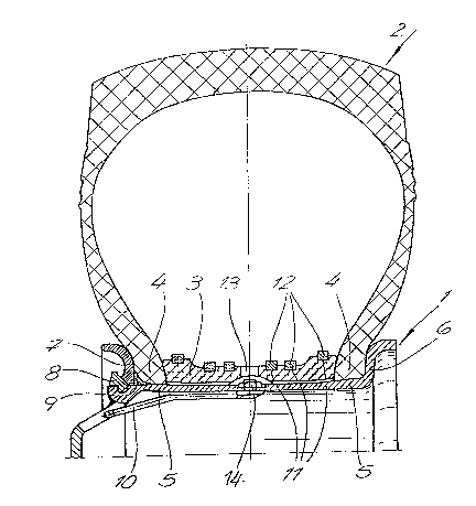
Figure 1 is part of a radial cross-section through a vehicle wheel
incorporating an expansion ring in accordance with the invention: and
; Figure 2 is a cross-section through the profiled section of theexpansion rinB of Flgure 1, prior to being formed into the ring.
The drawings show a vehicle wheel including a compound rim 1, a
tubeless pneumatic tire 2 and a wire strand reinforced expansion ring 3
positioned on the rim 1 to hold the tire beads 4 on the respective shoulders
5 of the rim 1, by providing a lateral force for pressing the tire beads 4
against a rim flange 6 and a side ring 7 of the compound rim, respectlvely.
~ide ring 7 is combined with a Eas~ener ring 8 and a seal ring 9. A valve
i 10 is positioned on the rim 1. The expansion rin8 3 is made from a profiled
section which is provided with longitudinal grooves 11 in its outer surface
and is cut to a length corresponding to the circumference of the rim
shoulders 5 or the tire beads 4. Wire bundle reinforcement rings 12 are
positioned in the grooves 11. Profiled section 3 is an extruded plastic
section, and its ends are complementarily mitered at right angles. The
section is formed into a circle with the mitered ends brought together and
subsequently vulcanized. The circularized section is provided with at least
one radial bore 13 adapted to align with the opening 14 from valve 10 in
order to permit pressurized air to enter the pneuma~ic tubeless tire 2. The
wire bundle rings 12 are positioned in the grooves 11 with a selected
pretension, several grooves 11 being positioned side by side and describing
circles of different diameters. The axially outer grooves describe circles
of larger dia=etere tha= the ax~ally Inner g~oovee.
PAT 15252-1
.
~ .
. : . : : . .
.. .. ~ . .

Dessin représentatif
Une figure unique qui représente un dessin illustrant l'invention.
États administratifs

2024-08-01 : Dans le cadre de la transition vers les Brevets de nouvelle génération (BNG), la base de données sur les brevets canadiens (BDBC) contient désormais un Historique d'événement plus détaillé, qui reproduit le Journal des événements de notre nouvelle solution interne.

Veuillez noter que les événements débutant par « Inactive : » se réfèrent à des événements qui ne sont plus utilisés dans notre nouvelle solution interne.

Pour une meilleure compréhension de l'état de la demande ou brevet qui figure sur cette page, la rubrique Mise en garde , et les descriptions de Brevet , Historique d'événement , Taxes périodiques et Historique des paiements devraient être consultées.

Historique d'événement

Description Date
Inactive : CIB de MCD 2006-03-11
Inactive : Abandon.-RE+surtaxe impayées-Corr envoyée 1997-01-15
Inactive : Demande ad hoc documentée 1997-01-15
Demande non rétablie avant l'échéance 1993-07-17
Le délai pour l'annulation est expiré 1993-07-17
Inactive : Demande ad hoc documentée 1993-01-15
Réputée abandonnée - omission de répondre à un avis sur les taxes pour le maintien en état 1993-01-15
Demande publiée (accessible au public) 1990-07-13

Historique d'abandonnement

Date d'abandonnement Raison Date de rétablissement
1993-01-15
Titulaires au dossier

Les titulaires actuels et antérieures au dossier sont affichés en ordre alphabétique.

Titulaires actuels au dossier
VORWERK & SOHN GMBH & CO. GROSSE EINHEIT
Titulaires antérieures au dossier
ULRICH PIEPENBRINK
Les propriétaires antérieurs qui ne figurent pas dans la liste des « Propriétaires au dossier » apparaîtront dans d'autres documents au dossier.
Documents

Pour visionner les fichiers sélectionnés, entrer le code reCAPTCHA :


Pour visualiser une image, cliquer sur un lien dans la colonne description du document. Pour télécharger l'image (les images), cliquer l'une ou plusieurs cases à cocher dans la première colonne et ensuite cliquer sur le bouton "Télécharger sélection en format PDF (archive Zip)" ou le bouton "Télécharger sélection (en un fichier PDF fusionné)".

Liste des documents de brevet publiés et non publiés sur la BDBC .

Si vous avez des difficultés à accéder au contenu, veuillez communiquer avec le Centre de services à la clientèle au 1-866-997-1936, ou envoyer un courriel au Centre de service à la clientèle de l'OPIC.


Description du
Document 
Date
(aaaa-mm-jj) 
Nombre de pages   Taille de l'image (Ko) 
Revendications 1990-07-12 2 86
Abrégé 1990-07-12 1 26
Dessins 1990-07-12 1 43
Description 1990-07-12 3 188
Dessin représentatif 1999-08-02 1 22
Taxes 1991-10-21 1 30