Sélection de la langue

Search

Sommaire du brevet 2008269 

Énoncé de désistement de responsabilité concernant l'information provenant de tiers

Une partie des informations de ce site Web a été fournie par des sources externes. Le gouvernement du Canada n'assume aucune responsabilité concernant la précision, l'actualité ou la fiabilité des informations fournies par les sources externes. Les utilisateurs qui désirent employer cette information devraient consulter directement la source des informations. Le contenu fourni par les sources externes n'est pas assujetti aux exigences sur les langues officielles, la protection des renseignements personnels et l'accessibilité.

Disponibilité de l'Abrégé et des Revendications

L'apparition de différences dans le texte et l'image des Revendications et de l'Abrégé dépend du moment auquel le document est publié. Les textes des Revendications et de l'Abrégé sont affichés :

  • lorsque la demande peut être examinée par le public;
  • lorsque le brevet est émis (délivrance).
(12) Brevet: (11) CA 2008269
(54) Titre français: FILTRE A AIR ROBUSTE AVEC SOUPAPE A NEIGE SOLIDAIRE
(54) Titre anglais: HEAVY DUTY AIR FILTER WITH INTEGRAL SNOW VALVE
Statut: Périmé et au-delà du délai pour l’annulation
Données bibliographiques
(51) Classification internationale des brevets (CIB):
  • F02M 35/024 (2006.01)
  • F02F 07/00 (2006.01)
  • F02M 31/06 (2006.01)
  • F02M 35/02 (2006.01)
  • F02M 35/04 (2006.01)
(72) Inventeurs :
  • MACHADO, JOSEPH (Etats-Unis d'Amérique)
(73) Titulaires :
  • ALLIEDSIGNAL INC.
(71) Demandeurs :
  • ALLIEDSIGNAL INC. (Etats-Unis d'Amérique)
(74) Agent: MACRAE & CO.
(74) Co-agent:
(45) Délivré: 1999-06-01
(22) Date de dépôt: 1990-01-22
(41) Mise à la disponibilité du public: 1991-04-02
Requête d'examen: 1996-12-18
Licence disponible: S.O.
Cédé au domaine public: S.O.
(25) Langue des documents déposés: Anglais

Traité de coopération en matière de brevets (PCT): Non

(30) Données de priorité de la demande:
Numéro de la demande Pays / territoire Date
415,839 (Etats-Unis d'Amérique) 1989-10-02

Abrégés

Abrégé anglais


An air cleaner assembly for a motor vehicle
includes and housing which carries a substantially flat
valve cover plate which defines a pair of openings. A valve
is slidable relative to the valve cover plate through a
linkage operated from the vehicle operator's compartment to
cover one or the other of the openings in the valve cover
plate. During normal operation of the vehicle, combustion
air is communicated to the air cleaner housing through the
normal air induction system. However, when heavy snow
blocks communication through the normal air induction
system, the vehicle operator operates the linkage to move
the valve to a position opening the other opening into the
air cleaner, so that underhood air may be used for
combustion as long as the normal air induction system is
blocked by snow.

Revendications

Note : Les revendications sont présentées dans la langue officielle dans laquelle elles ont été soumises.


-5-
Claims
1. Air cleaner assembly for a motor vehicle
comprising a housing, said housing having a
circumferentially extending wall defining a chamber
therewithin and a pair of end walls extending transversely
with respect to the circumferentially extending wall and
closing opposite ends of said chamber, a filtering
cartridge received within said chamber, said filtering
cartridge having an upstream side and a downstream side,
an outlet opening defined in one of said end walls
communicating with the downstream side of said filtering
cartridge, and a pair of inlet openings defined on the
circumferentially extending wall, each of said inlet
openings communicating with the upstream side of said
filtering cartridge, a valve slidably mounted on said
circumferentially extending wall for movement from a first
position covering one of said inlet openings to a second
position covering the other inlet opening, and linkage
means operable by the vehicle operator for moving said
plate between the first and second positions.
2. Air cleaner assembly as claimed in claim 1,
wherein said inlet openings are defined on a valve cover
plate mounted on said circumferentially extending wall,
said valve being mounted for sliding movement relative to
said valve cover plate.
3. Air cleaner assembly as claimed in claim 2,
wherein supporting legs project from said circumferentially
extending wall to define a mounting surface, said
valve cover plate having a pair of opposite edges, said
opposite edges being supported by said supporting legs,
said inlet openings being apertures formed in said valve
cover plate.
4. Air cleaner assembly as claimed in claim 2,
wherein said legs define guiding tracks for guiding said
valve for movement along said valve cover plate, said
valve cover plate including a pair of projections
cooperating with a corresponding one of said tracks.

-6-
5. Air cleaner assembly as claimed in claim 4,
wherein said tracks extend parallel to the axis of said
housing defined by said circumferentially extending wall
for guiding movement of said valve in a direction
substantially parallel to said axis.
6. Air cleaner assembly as claimed in claim 4,
wherein said linkage means includes a lever, first pivot
means mounting said lever for pivoting relative to said
housing, a rod, second pivot means pivotally connecting
one end of the rod to said lever, and control means
manipulatable by the vehicle operator for pivoting said
lever.
7. Air cleaner assembly as claimed in claim 6,
wherein said first pivot means mounts said lever on said
valve cover plate for pivoting relative thereto.
8. Air cleaner assembly as claimed in claim 4,
wherein said valve slides between said valve cover plate
means and said legs.
9. Air cleaner assembly as claimed in claim 1,
wherein said linkage means includes a lever, first pivot
means mounting said lever for pivoting relative to said
housing, a rod, second pivot means pivotally connecting
one end of the rod to said lever, and control means
manipulatable by the vehicle operator for pivoting said
lever.
10. Air cleaner assembly as claimed in claim 4,
wherein both said valve cover plate and said valve are
substantially flat.

Description

Note : Les descriptions sont présentées dans la langue officielle dans laquelle elles ont été soumises.

' 2~0826~
HEAVY DUTY AIR FILTER WITH INTEGRAL SNOW VALVE
This invention relates to an air cleaner assembly
for a heavy duty vehicle which includes an integral snow
valve.
Heavy equipment, such as highway maintenance
05 trucks and other vehicles used where heavy snows are
common often are subjected to clogging of the vehicle
engine air intake system with snow. Such clogging results
in poor engine performance, and often makes the engine
completely inoperable. Accordingly, it has become common
in such vehicles to provide a valve which switches the
inlet of the vehicle engine air cleaner from the normal
air intake system to underhood air during such heavy snow
conditions. However, prior art air intake systems from
such vehicles mounted the snow valve separate from the air
cleaner, and it was often difficult to easily switch the
snow valve from the normal air induction system to the
underhood air intake. Furthermore, such remote snow
valves were also undesirable because they added cost to
the system, and were often inconvenient to package in the
space available.
The present invention incorporates a snow valve
integral with the air cleaner housing. The snow valve is
capable of switching between the normal air intake system
and underhood air under snow clogging conditions, but does
not appreciably chanye the contour of the air cleaner
itself. Accordingly, the air cleaner with the inte~ral
snow valve pursuant to the present invention may be
packaged anywhere a conventional air cleaner may be
packaged. Furtherrnore, the snow valve may be easily
operated, through a cable connection with the vehicle
operator's compartment, to switch the snow valve from the
normal condition in which air inducted through the normal
air intake s~stem is used to using underhood air under
snow clogging conditions.
These and other advantages of the invention will
become apparent from the following description, with
reference to the accompanying drawings, in which

' 2~826~
-- 2
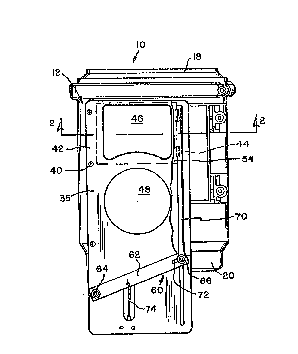
Figure 1 is a top plan view of an air cleaner
with an integral snow valve made pursuant to the teachings
of the present invention;
Figure 2 is a transverse cross-sectional view
05 taken substantially along lines 2-2 of Figure l; and
Figure 3 is a cross-sectional view taken
substantially along lines 3-3 of Figure 2.
Referring now to the drawings, an air cleaner
generally indicated by the numeral 10 includes a housing
12 having a circumferentially extending outer wall 14
defining a chamber 16 therewithin. A pair of transversely
extending end walls 18, 20 close opposite ends of the
chamber 16. A filtering cartridge generally indicated by
the numeral 22 is received within the charnber 16, and
includes a conventional pleated paper filtering medium 2
consisting of a circumferentially extending array of
radially tapering pleats. An outer screen 26 and inner
screen 28 circumscribe the media 24 to provide radial
support of the latter. Upper and lower sealing end caps
30, 32 circumscribe the medium 24 and provide sealing
engagement with the corresponding end cap 18, 20. The
outer screen 26 defines the upstream side of the
cartridge, and cooperates with the wall 14 to divide the
chamber 16 into inlet section general.ly indicat~d by the
numeral 34. The inner screen 2~ defines the downstream
side of the cartridge 22 and de~ines an outlet chamber
36. Outlet chamber 36 communicates with an outlet opening
38 defined on end wall 20.
A substantially flat valve cover plate 35 is
mounted on circumferentially spaced, projecting legs 37,
39 e~tending ~rom the circurnferentlally extending wall 14
to define a substantially flat mounting surface. Valve
cover plate 35 is secured to the legs 37, 39 by screws 40
e~tending through opposite edges 42, 44 of the valve cover
plate 35 into the legs 37, 39. A pair of inlet openings
46, ~8 are defined in the valve cover plate 35. Normally,
the air cleaner 10 is mounted in the engine compartment
with the valve cover plate 35 extending directly beneath

2~82~
-- 3
the hood (not shown) of the vehicle. The normal air
induction system of the vehicle consists of an inlet air
duct which e~tends through the hood of the vehicle and,
when the hood is closed, sealingly engages with the
05 opening 48 to communicate ambient air from outside of the
engine compartment to the opening 48. The opening 46 is
open to the air within the vehicle engine compartment.
Yrojections 50, 52 project Eorm opposite edges of a valve
generally indicated by the numeral 54. Projections 50, 52
are slidably received in tracks 56, 58 defined between the
legs 37, 41 and the legs 39, 43. Accordingly, the valve
54 is supported by the legs 91, 43 and guided by the
tracks 56, 58 for sliding movement relative to the plate
35. The valve 54 is supported between the valve cover
plate 35 and the legs 37, 39, and, since the legs 37, 39
are substantially parallel to the axis defined by the
cartridge 22, the valve 54 also moves substantially
coaxial with the cartridge 22.
Movement of the valve 54 between the first
position in which the underhood air inlet 46 is covered
and air is communicated into the housing 12 through the
outside air inlet 48 and a second position in which the
outside air inlet is covered and the underhood air inlet
46 is opened is effected by a linkage assembly generally
indicated by the numeral 60. Linkage 60 includes a lever
62 which is pivotedly mounted on valve cover plate 35 by a
first pivot 64. A second pivot 66 is provided at a
turned-up end of rod 70. Elongated slot 72 provided in
lever 62 prevents rod 70 ~rom binding during pivoting of
lever 62. Rod 70 is attached to valve 54 by wel~ing.
Pivoting of the lever 62 is efEected through a cable 74,
which connects the lever 62 with an operating lever (not
shown) in the vehicle operators compartment.
As discussed above, when the air cleaner 10 is
mounted on the vehicle, the valve cover plate 35 is
immediately below the hood of the vehicle, and e~tends
roughly parallel thereto. The normal air induction
system, consisting of a series of conduits, extends

~a~82~
-- 4
through the hood to communicate with the opening 48 in the
valve cover plate 35. Normally, a circumferentially
extending "donut" of elastic material is mounted on tlle
inside of the hood circumscribing the opening of the air
05 induction system through the hood. When the hood is
closed, this donut of sealing material sealing engages the
portion of the valve cover plate 35 circumscribing the
opening ~, to thereby provide a substantially air tigh-t
connection between the air induction system extending
through the vehicle hood and the opening 48. Durin~
normal operation of the vehicle, ambient air is
communicated through the opening 48 into the chamber 16,
where it is cleaned by the filtering element 22 before
passing into the outlet charnber 36 defined by inner screen
28 and outlet opening 3~ defined in the end wall 20, from
where it is communicated to the induction manifold of the
vehicle engine.
However, when vehicles are operated in heavy snow
areas, the normal air induction system sometimes becomes
clogged with snow, thereby rendering the vehicle partially
or wholly inoperable because the engine is starved for
combustion air. When this occurs, the vehicle operator
may move the aforementioned lever (not shown) in the
vehicle operator's compartment, which is connected by
cable 74 to the lever 62, moving the lever 62 clockwise
viewing Figure 1, thereby forcing the valve 5~ from its
normal position covering the inlet 46 to a position
covering the inlet 4B and opening the inlet ~6. Since the
inlet 46 is open to underhood air, the engine may be
started and is able to run. Of course, it is desirable to
use the ambient air communicated through opening 9~ when
possible, since this air is cooler and therefore more
dense, so that the engine runs more efficiently. ~lowever,
the ability o~ the valve 54 to open the inlet 46 to use
the underhood air permits the vehicle to be started and
operated in the event that snow clogs the inlet air
conduits communicated with opening 4~.
- . ':' .
- . ' '

Dessin représentatif
Une figure unique qui représente un dessin illustrant l'invention.
États administratifs

2024-08-01 : Dans le cadre de la transition vers les Brevets de nouvelle génération (BNG), la base de données sur les brevets canadiens (BDBC) contient désormais un Historique d'événement plus détaillé, qui reproduit le Journal des événements de notre nouvelle solution interne.

Veuillez noter que les événements débutant par « Inactive : » se réfèrent à des événements qui ne sont plus utilisés dans notre nouvelle solution interne.

Pour une meilleure compréhension de l'état de la demande ou brevet qui figure sur cette page, la rubrique Mise en garde , et les descriptions de Brevet , Historique d'événement , Taxes périodiques et Historique des paiements devraient être consultées.

Historique d'événement

Description Date
Inactive : CIB de MCD 2006-03-11
Le délai pour l'annulation est expiré 2002-01-22
Lettre envoyée 2001-01-22
Accordé par délivrance 1999-06-01
Inactive : Page couverture publiée 1999-05-31
Préoctroi 1999-02-26
Inactive : Taxe finale reçue 1999-02-26
Inactive : Lettre officielle 1998-12-22
Inactive : Transferts multiples 1998-10-27
Lettre envoyée 1998-10-06
Un avis d'acceptation est envoyé 1998-10-06
Inactive : Dem. traitée sur TS dès date d'ent. journal 1998-09-30
Inactive : Renseign. sur l'état - Complets dès date d'ent. journ. 1998-09-30
Inactive : Approuvée aux fins d'acceptation (AFA) 1998-08-20
Toutes les exigences pour l'examen - jugée conforme 1996-12-18
Exigences pour une requête d'examen - jugée conforme 1996-12-18
Demande publiée (accessible au public) 1991-04-02

Historique d'abandonnement

Il n'y a pas d'historique d'abandonnement

Taxes périodiques

Le dernier paiement a été reçu le 1998-12-23

Avis : Si le paiement en totalité n'a pas été reçu au plus tard à la date indiquée, une taxe supplémentaire peut être imposée, soit une des taxes suivantes :

  • taxe de rétablissement ;
  • taxe pour paiement en souffrance ; ou
  • taxe additionnelle pour le renversement d'une péremption réputée.

Les taxes sur les brevets sont ajustées au 1er janvier de chaque année. Les montants ci-dessus sont les montants actuels s'ils sont reçus au plus tard le 31 décembre de l'année en cours.
Veuillez vous référer à la page web des taxes sur les brevets de l'OPIC pour voir tous les montants actuels des taxes.

Historique des taxes

Type de taxes Anniversaire Échéance Date payée
TM (demande, 8e anniv.) - générale 08 1998-01-22 1997-12-31
Enregistrement d'un document 1998-10-27
TM (demande, 9e anniv.) - générale 09 1999-01-22 1998-12-23
Taxe finale - générale 1999-02-26
TM (brevet, 10e anniv.) - générale 2000-01-24 1999-12-20
Titulaires au dossier

Les titulaires actuels et antérieures au dossier sont affichés en ordre alphabétique.

Titulaires actuels au dossier
ALLIEDSIGNAL INC.
Titulaires antérieures au dossier
JOSEPH MACHADO
Les propriétaires antérieurs qui ne figurent pas dans la liste des « Propriétaires au dossier » apparaîtront dans d'autres documents au dossier.
Documents

Pour visionner les fichiers sélectionnés, entrer le code reCAPTCHA :


Pour visualiser une image, cliquer sur un lien dans la colonne description du document (Temporairement non-disponible). Pour télécharger l'image (les images), cliquer l'une ou plusieurs cases à cocher dans la première colonne et ensuite cliquer sur le bouton "Télécharger sélection en format PDF (archive Zip)" ou le bouton "Télécharger sélection (en un fichier PDF fusionné)".

Liste des documents de brevet publiés et non publiés sur la BDBC .

Si vous avez des difficultés à accéder au contenu, veuillez communiquer avec le Centre de services à la clientèle au 1-866-997-1936, ou envoyer un courriel au Centre de service à la clientèle de l'OPIC.

({010=Tous les documents, 020=Au moment du dépôt, 030=Au moment de la mise à la disponibilité du public, 040=À la délivrance, 050=Examen, 060=Correspondance reçue, 070=Divers, 080=Correspondance envoyée, 090=Paiement})


Description du
Document 
Date
(aaaa-mm-jj) 
Nombre de pages   Taille de l'image (Ko) 
Dessin représentatif 1999-05-24 1 13
Dessins 1993-11-04 2 49
Abrégé 1993-11-04 1 19
Description 1993-11-04 4 179
Revendications 1993-11-04 2 73
Dessin représentatif 1998-07-20 1 16
Avis du commissaire - Demande jugée acceptable 1998-10-05 1 163
Avis concernant la taxe de maintien 2001-02-18 1 176
Correspondance 1999-02-25 2 53
Correspondance 1998-12-21 1 4
Taxes 1996-12-29 1 56
Taxes 1995-12-27 1 55
Taxes 1994-12-21 1 75
Taxes 1993-12-21 1 61
Taxes 1992-12-29 1 38
Taxes 1991-12-18 1 26
Correspondance de la poursuite 1996-12-17 1 36
Correspondance de la poursuite 1997-03-18 2 69