Note : Les descriptions sont présentées dans la langue officielle dans laquelle elles ont été soumises.
gl9
BACKG~OUND oY T~E INVENTION
1. Field of the Invention
The present invention relates to a rack or basket for
automatic dishwashers. The rack includes a lower rack member
having a pexforated, preferably grate-like bottom wall and
frame side wall members and an upper frame member arranged
above the lower rack member. The lower rack member and the
upper frame member are connected to each other in a
positively engaging manner by means of vertical support
members or columns. The vertical support members are
received in recesses provided in the lower rack member and in
the upper frame member. The cross-sectional contours of the
recesses correspond to those o~ the support members.
2. Description of the Related Art
Many dishwasher racks of the above-described type are
known in the art. Automatic dishwashers are used in hotels,
restaurants and cafeterias for cleaning glasses, dishes,
cutlery and other pieces. In addition to being used in
dishwashers, some of the known dishwasher racks can also be
used for storage and transport purposes, particularly in the
case of glasses. Drinking glasses have different shapes and
sizes. Because of the mechanical and thermal loads and
because of the glasses being handled in the kitchen and in
Z~ 9
restaurants, glasses are particularly susceptible to being
damaged and to breaking. In order to reduce this damage to a
minimum, glasses which are in danger of being damaged are
protected at the ends by divisions in the rack.
For the above-described reason, known dishwasher racks
are provided with upper frame members which also may
partially have divisions as necessary. The upper frame
member also serves to stack several dishwasher racks above
each other with dishes being placed in the racks.
A dishwasher rack of this type has a lower rack portion
with a grate like perforated bottom and four frame side wall
members. An upper frame member can be placed onto the frame
formed by the four frame side wall members. These components
can also be connected to each other in a positively engaging
manner. This engagement is effected by means of upwardly
projecting steps or lugs on the frame of the lower rack
portion which are received in corresponding recesses at the
bottom side of the upper frame member. Grate-like dividing
members are suspended or fastened in the upper frame member
and/or in the lower rack member, wherein each section of the
divisions has the purpose to receive a drinking glass.
Depending on the height of the drinking glasses, it is also
possible to place several upper frame members on the lower
rack member until the desired height is reached which is
necessary for supporting the glasses placed in the dishwasher
2~
rack for cleaning in a secure and stable manner. In the
known rac~s, the upper frame members are connected to each
other to form a rigid s~ructural unit by using vertical pipes
or rods or by connecting the upper frame members which have
been placed on the lower rack member.
It is the primary object of the present invention to
simplify the structure of the known dishwasher racks. In
particular, the assembly of the racks is to be made simpler,
iOe., the assembly of the rack members by the manufacturer is
to be made simpler or the assembly by the user of the rack is
to be made simpler, so that the individual components of the
rack can be combined in accordance with specific
requirements. Also, this assembly is to be possible without
requiring special or complicated tools.
SUMMARY OF THE INVENTION
In the accordance with the present invention, the
vertical support members are rails which are L-shaped in
cross-section. A row of holes is provided in at least one of
the two sides of the rail and a cutout forming a flap is
provided in at least one of the two sides of the rail in the
lower portion thereof and underneath the row of holes. The
flap is resilient in a direction transversely of the axis of
the rail and has at the outer side thereof a step which
projects from the plane of the side of the rail.
The various features of novelty which characterize the
invention are pointed out with particularity in the claims
annexed to and forming a part of this disclosure. For a
better understanding of the invention, its operating
advantages and specific objects attained by its use,
reference should be had to the drawing and descriptive matter
in which there is illustrated and described a preferred
embodiment of the invention.
BRIEF DESCRIPTION OF THE DRAWING
In the drawing:
Fig, 1 is an elevational side view of a dishwasher rack
according to the present invention including a lower rack
portion and an upper rack portion;
Fig. 2 is a sectional view, on a larger scale, taken
along sectional line II-II in Fig. 1;
Fig. 3 is a sectional view, on a larger scale, taken
along sectional line III-III in Fig. l;
Fig. 4 is a front elevational view of a vertical support
member;
Fi~. 5 .is a side view, partially in section, of the
support member of Fig. 4;
Fig. 6 is top view of the support member of Fig. 4; and
Fiy. 7 is a side view, partially in section, of a corner
of the lower rack portion between the direction of arrow A in
Fig. 2.
DESCRIPTION OF THE PREFERRED EMBODIMENT
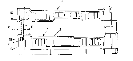
Fig. 1 of the drawing shows in a side view a dishwasher
rack which includes a lower rack member 1 with a perforated,
grate-like bottom 2 and four frame side wall members 3 which
are also advantageously perforated. Vertical support members
4 are provided at the corners of the lower rack member 1~
The support members 4 carry an upper frame member 5. Bores 6
are provided on the upper edges of the frame side wall
members 3 of the lower rack member 1 and on the upper frame
member 5. Web-like or grate-like partitions, not illustrated
in detail, can be suspended from and fi~ed in the bores 6.
These partitions define within a rack zones in which a glass
or another dish to be cleaned is placed.
The spacing between lower member 1 and upper member 5
differs depending on the size and shape of the ~lasses or
dishes to be cleaned. This spacing is determined by the
Zq~ 9~L~
vertical support members 4. ~nstead of the web-like or
grate-like partitions mentioned above, lt is also possible to
use oth~r inserts to be mounted in the dishwasher rack, for
example, inserts in which plates can be inserted and which
have the purpose to maintain the plates in an upright
position.
A vertical support member 4 is illustrated in detail in
Figs. 4-6. The support member 4 is a rail which is L-shaped
in cross-section and has two side members 7 and 8. Side
member 7 has a row of several holes 9 of equal diameter which
are arranged vertically one above the other. A flap 10 is
provided by a cutout made in the lower portion of the support
member 4 and underneath the above-mentioned row of holes 9.
The flap 10 is resiliently movable transversely of the axis
of the L-shaped rail. Flap 10 has at its outer side a step
11 which projects from the plane E1 of the side member 7.
The portion of the flap 10 extending downwardly from the step
11 is shaped so as to narrow conically towards the bottom.
Portion 12 of the flap 10 above the step 11 is preferably
somewhat thinner, i.e., it has a thinner wall thickness than
the side member 7 of the support member ~.
As can be seen from the top view of Fig. 6, the
longitudinal edge of the side member 7 in which the flap 10
is provided has a rearwardly projecting rim 13, the inner
height h of which corrPsponds approximatély to the path of
2~C~89~
resilient movement of the flap 10, so t.hat when the flap 10
is pushed in the direction of arrow B until its outer edge
which forms the space 11 is located in the plane indicated in
Fig. 6 by line E1, the flap 10 does not move back ~urther
than to the region indicated in Fig. 6 by line E2.
The components discussed above are advantageously all
made of a suitable plastics material.
Recesses 14 and 18, respectively, are provided in the
corner areas of the lower rack member 1 and of the upper
frame member 5 for receiving the vertical support members 4.
The recesses 14 and 18 have cross-sections which correspond
to the L-shaped cross-section of the support member 4. The
portion of the recess 14 in the lower rack member 1 which
receives the side 7 with the flap 10 has a width over its
length 1 which corresponds to the outer height H at the rim
of the side 7. In order to limit the distance by which the
support member 4 can be slid into the recess 14, the portion
of the recess 14 which is near the bottom has inwardly
projecting, step-like pro~ections 15 which reduce the cross-
section of the recess 14 and prevent the support member 4
from being pushed through the recess. In order to fix the
inserted support member 4, recesses 17 are provided in the
outer wall 16 of the frame side wall members 3 of the lower
rack portion 1 which define toward the outside the recess 14
for receiving the support member 4. The step 11 of the flap
XC)~9~
10 enga~es in a locking manner in the recess 17 when the
support member 4 is inserted, so that the support member 4 is
held in a positively engaging manner. The support member 4
can be removed from the recess 14 when the flap 10 is pressed
rearwardly by reaching through recess 17.
The L-shaped recesses 18 for receiving the upper portion
of the support member 4 provided in the corner areas of the
upper frame member 5 extend over the height of the upper
frame member 5 and include a countersunk bore in the outer
wall which extends through the wall of the member 5 in the
corner region thereof. This bore 19 serves to receive a
spreading bolt 20.
The axis of the spreading bolt 20 extends transversely
over the longitudinal axis of the support member 4 and has at
its end a flat head 21. The other end of the bolt 20 has an
incision 22. A conical attachment 23 is provided on the bolt
extending over the axial length of the incision 22. The
diameter at the base of this conical attachment 23 is greater
than the diameter of the shaft 2~ of the spreading bolt 20,
so that an undercut is formed.
It is further clear from the above-described figures
that the L-shaped recesses 14, 18 in the frames of the lower
member 1 and the upper member 5 for receiving the support
members 4 are provided in the corner areas and one side 7 of
the support member ~ e~tends in one side of the frame and the
other side 8 of the support member ~ extends in the other
side of the frame.
The lower rack portion 1 and the upper frame portion 5
have a predetermined size and shape. The support members 4
are advantageously manu~actured in se~eral leng~hs. The
support members ~ can be easily cut to the desired length
depending on the shape of the glasses and the size of the
glasses to be cleaned. When the rack is assembled, the
support members 4 are initially inserted in the recesses 14
in the lower rack portion l until they are locked by means of
the Elaps and the recesses 17 and, thus, these components are
positively engaged in each other. The upper frame member 5
is now placed on the support members 4 which may have been
previously cut to size. The upper ends of the support
members ~ are received b~ the recesses 18 in the corner
areas. When the intended height or the intended vertical
distance between lower member 1 and upper member 5 is
ad~usted, the spreading bolts 20 are inserted or pressed in,
so that the bolts 20 also form a positively engaging
connection, as indicated in Fig. 3. The grate-like dividing
members are now assembled or other holding means are
inserted. The dishwasher rack is now ready for its intended
purpose.
9~
Without departing from the scope of the invention, the
flap 10 and the bores 9 of the row of bores may be provided
in different sides of the support member 4. Also, the outer
bent rim 15 at the side 7 of the support member 4 may be
omitted. In this case, the flap 10 has a thin wall
thickness, ~o that it can yield in a transverse movement when
the support member 4 is inserted without projecting over the
rear plane or surface of the side 7. The bent longitudinal
rim 13 and the corresponding shape of the recess 14 provides
a free space for the flap 10 in which it can move when the
support member 4 is inserted. As already mentioned, this
space can also be obtained in a different but equivalent
manner which requires that at least that side of the support
member 4 in which the flap is provided has a sufficiently
large wall thickness. The wall of the recess 14 of the
support member 4 may also be stepped in order to provide a
free space for the flap 10 in this manner.
As described above, the positively engaging connection
between the support member 4 and the lower member 1 is
effected by the flap 10, and a recess 17 and the upper member
5 is connected to the support member 4 by means of spreading
bolts 20. However, it would also be possible to exchange the
two forms of connection, so that the spreading bolt 20 is
provided in the corner region of the lower rack member 1 and
a connection with the flap is provided in the upper frame
11
z~
member 5. It is further possible to provide a rivet-like
connecting or fastening member instead of the spreading bolt.
While a specific embodiment of the invention has
been shown and described in detail to illustrate the
application of the inventive principles, it will be
understood that the invention may be embodied otherwise
without departing from such principles.