Note : Les descriptions sont présentées dans la langue officielle dans laquelle elles ont été soumises.
- 2 _ zn~ 9~ 5 2
Technical Field of the Invention
The invention ~elates to an effluent treatment system and in
particular to a system for treating effluent which ha~ passed
through a primary treatment step, for example through a septic
tank, to remove a substantial proportion of solids.
Septic tank~ are used in a variety of locations to cope with
effluent from domestic and industrial ~ites. In rural
Ireland, for example, there are presently 400,000 septic tanks
to serve approximately one million people who do not have
access to a public ~ewage system. Considerable pollution
risks are posed by the discharge from ~eptic tank~. Effluent
seeping into ground with excessive ~oakage may percolate away
to pollute a ground water ~ource. Where ground soakage is
insufficient, ~rface water system6 may ~e polluted due to
effluent discharges.
Prior Art
~t is known to use some types of peat as biological treatment
media. While such media are effective in treating e~fluent
there is a tendency for the peat bed to become saturated if
loadings in excess of minimum loadings are applied. Thi~ is
known as ~ponding~ and has the effect of ~ubstantially
reducing the effectiveness of the peat bed to perform its
bioloqical treatment function. To overcome this difficulty
the loading rate on the peat be~ i~ reduced. Thus, peat beds
can acco~modate only relatively low loading~ which, bQcause of
_ 3 _ 2009752
the large surface area required, are expensive and
impractical to use in many applications.
Ob~ect of the Invention
This invention is directed towards providing an improved
effluent treatment system which will overcome these and
other difflculties with known systems.
Summary of the Invention
According to the invention there is provided an effluent
treatment system for treating effluent which has passed
through a primary treatment to remove a substantial
proportion of solids comprising:
a container having an upper inlet for effluent from
a primary treatment and a lower outlet for treated
effluent,
a biological effluent treatment medium in the
container,
the biological ef f luent treatment medium comprising
a homogenous mixture of biologically active peat and
an organic fibrous material,
We have found that the incorporation of an organic fibrous
material, particularly peat-based organic fibrous material
having a relatively low absorptive capacity reduces
ponding or clogging of the treatment medium and promotes
drainage and as a consequence provides a system which can
accommodate very high loading rates whilst retaining its
capacity to effectively treat the effluent.
~. ~,7 7 .,
2009752
-- 4
In one embodiment of the invention the ratio of peat to
fibrous material in the medium is in the range of 10:90 to
90:10 by volume, preferably in the range 20:80 to 80:20,
most preferably approximately 50:50. The higher the
proportion of fibre the greater the ability of the medium
to allow flow of effluent through. However, the higher
the proportion of fibre in general the less the biological
activity of the medium.
In a preferred embodiment of the invention the
biologically active peat is a young Sphagnum peat.
Young Sphagnum peat is preferred because of its high
water-holding capacity.
Preferably the peat is of a Von Post humification scale Hl
to H" most preferably H,. Such peat i5 preferred because
of its high water-holding-capacity.
In a particularly preferred embodiment of the invention
the organic fibrous material is a peat fibre material.
"~5
~A
~0091 5~
Organ~c flbrs~s material, most preferably pea* fibre i9
preferred because o~ lts compat$bility wlt~ the peat.
Preferably the pe~t flbre con~i~t~ m~$nly of root rQ8idue~ of
erlophorum ~cottongras~) plant~ extracted f~am bog peats.
In one embod~ment of the invention thQ mlxture i8 compacted by
from 20% to 7S% ~y volume, preferably 30 to 60% by volume,
mo~t preferably approximately 50% by volume. The loose- the
med$um the greater the rlsk of effluent flowlng though without
being treated. At higher level~ of compaction~ however, the
greater the risk of the flow of l~quid being retarded to the
extent th~t ponding occur8.
Preferably ~n upper ef~luent di~tribution medium i5 pro~ided
a~ove the biologlcal effluent treat~ent medlum to distribute
effluent at the upper surface of the medium.
n a preferred ~rrangement the distrlbution medium i~ of an
organ$c flbrous mater$al for compatlb~llty wlth the treatment
medium.
Prefer~bly ~ lower outlet flow inducing medium i8 pro~ided
below the biological effluent treatment medium at or ad~acent
to the effluent outlet.
20097S2
- 6 -
In a preferred arrangement the out~et flow inducing medium is
an organic fibrous material for compatibility with the
treatment medium.
In one embodiment of the invention the depth of the effluent
treatment medium is in the range 0.5 to 1.0 metres, most
preferably appro~imate~y 0.75 metres for long term biological
effectiveness of the system.
In a preferred embodiment of the invention the surface area of
the effluent treatment medium i8 at least 7 square metres for
a hydraulic load}ng of in the order of 7cm to 15cm per day of
effluent.
In one arrangement the container has a top opening closed by
an air permeable lid. The lid may comprise a perforated cover
having an odour control layer of fibrous material.
In a preferred embodiment the system include~ mean~ for
distributing e~fluent across the ~urface o~ the e~fluent
treatment medium.
In one arrangement the means for distributing effluent
comprises a rosette type distributor ha~ing a central inlet
and a plurality of spaced-apart outlets fed from the common
inlet. Pre~erably the distributor is a unitary formed
200975
-- 7 --
structure, preferably a moulded body of polystyrene or the
like.
In another arrangement the means for distributing effluent
comprises a sheet of corrugated or the like material having a
plurality of spaced-apart outlet holes.
In a further arrangement the mean~ for distributing effluent
across the surface of the effluent treatment medium comprises
at least one pipe extending above the treatment medium, the
pipe having a plurality of spaced-apart outlet holes.
Preferably a layer of stone chippings iB provided underneath
the pipe outlets for spreading and dlstributing e~fluent to ~e
treated.
Preferably a layer of peat material i~ provided above the
stone chippings for odour control.
In one embodiment of the invention the container is of a
modular form, a number o~ container~ being joined together and
the effluent to be treated being sp~ead acros~ the containers,
in parallel flow.
20097S2
-- 8 --
Brief Description of the Drawinq~
The invention will be more clearly understood from the
following description thereof given by way of example -only
with reference to the accom~an~ing drawings in which:
Fig. 1 is a schematic side view of an effluent treatment
sy~tem according to tho invention, in u~e,
~ig. 2 is a schematic side view of the effluent treatment
system in another arrangement, in use,
Fig. 3 is a plan view of a layout of an effluent
treatment system according to the invention,
Fig. 4 is a cross-sectional view on the line Y - Y in
Fig. 3,
Fig. 5 Ls a top plan view on an enlargéd scale of one
module of the treatment system of ~ig. 3,
lS Fig. 6 is a side view of the module of Fig. 5,
~ig. 7 is a side cross sectional view of a module,
Fig. 8 is a top plan view of one distri~ution portion of
one module,
r -- F 1~ ~ ~ k3
~Q97S2
g
Fig. 9 is a cross-sectional view on the line Z - Z in
Fig. 8,
Fig. 10 is an underneath plan view of the distribution
portion of ~ig. 8,
Fig. 11 is a plan view of another sy~tem according to the
~nvention,
Fig. 12 is a side cros~-sectional view of a module of the
system of Fig. 11,
Fig. 13 i8 a schematic side cross-sect~onal ViQW of
another effluent treatment system according to the
invent~on, and
Fig. 14 is a diagrammatic view of ano~her effluent
treatment system, in use.
Detailed De~criPtion o~ the Invention
Referring to the drawings and ini~ially to Figs. 1 to 10
thereo~ there is illustrated an effluent treatment system
according to the invention and indicated generally by the
reference numeral 1. The system 1 is in this case for
t~eating treated effluent from a septic tank 50 which receives
effluent from a single dwelling 51. The system 1 may be fed
by pumping using a pump 52 as illustrated in Fig. 1 or gravity
200~752
- 10 -
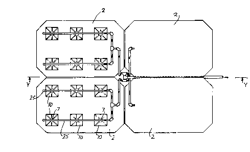
fed as illustrated ln Flg. 2. ~he treatmQnt syJte~ 1 Ls ln
thLs ca~e o~ modular constructlon and compri~e~ ~ number of
biological treatment modules 2. In this case there are four
modules ~rranged ~9 lllustrated in F$g. S.
Referring particularly to Figs. 4 to 7 eAch of the modules 2
comprises a t~nk or container 5 for a biolog1cal treatment
medium4l, each container 5 hav1ng lnlets 7 for effluent ~rom
a septic tank 50 and outlets l3 for flltered effluent. The
conta~ner S 18 ~n ~hi~ case closed by n alr permeable lld 16
comprising a cover 16 whlch c~rrles a layer of pe~t flbre
materi~l 17 to reduce odour. ~he odour control l~yer of
fibrous material may be held in place by a lower pla~tics mesh
layer and, if neces~ary to retAin the flbrou~ materisl in
place, al~o an upper plastics me~h layer. Means fo~
distributing effluent o~er the filter medium 6 of each module
2 ~n this caQe comprises four rosette distributor.s 10, one of
which is illustrated in detail in Figs. 8 to 10. Each
distributor 10 has a central ~nlet 12 and a plurality of
spaced-apart opeuings 18 which are fed from the common inlet 12
by gra~ity flow. The di~tributor is in this ca~e of moulded
polystyrene construction and the di~tributor~ 10 rest o~ top
of the treatment medium 41 as illustrated in Flg. 7.
In use, the modules 2 are installed partially below ground
le~el lS as illustrated in Fig. 2 and effluent from 8 ~eptic
tank may be pumped from a 8ump through ~ maln inlet pip~ 20
A
r~
0 9 ~ 5 ~
located below ground level ~hlch i~ connected to
di~tributlon pl~e network to the treatment medium 4I by
rl~er~ 26. Altern~tively, the effluent flow~ by gravity to
the treatment plant. The dLstribution pipe network 25
include~ outlet opening~ 28 which di~charge effluent to the
central inlet~ 12 of the ro~etto distrlbutor~ 10 a8 wlll be
apparent from F~g. S. The ~in upper dlstrlbution pipe
network 25 18 hung by pla~t~c or w~re tLed ~oints 30 from
support braces 32.
A~ will be apparent from Fig~. ~, 6 and 7 the outlets 13 are
provided by a plurality of spaced-apart drain holes 3~
extend~ nq around the b~se of the conta$ner 5 and which
discharge to a effluent collection plpe 35 through which the
treated effluent pa~ses by gra~ity flow to ~ discharge point.
It will be noted that the outlet~ from the treatment system
are provided with filter~ 60 which in ~his case are of organic
heather material or stone chlppings of 18mm average size.
It will be appreciated that the treatment plant 1 i~ of
modular con~truction and may be ~ized to accommodate a desired
flow of effluent by including more or le5~ modules than those
illu~trated. The size and configur~tion of the treatment
plant will depend on a number of factor6 including the
quantity and quality of the effluent to be treated. Typically
effluent from a septic tank will be discharget into a 8ump and
pumpet into the treatment plant, typically at a dome~t~c rate
~ ~ R
Z0097S2
- 12 -
of approximately 750 litre~ per day. Normally, the discharge
would be applied in approximately eight pumping batches and
the pumping would be float switch controlled. For larger
systems (i.e. multiple house) the inlet pump may be controlled
by level probes in the sump and/or perhaps by a timing
mechanism.
Effluen~ Treated
In all cases the effluent treated by the system of the
in~ention has already passed through a primary treatment step/
for example through a septic tank, which removes sol~ds and
provides anaero~ic treatment of sewage-type effluent.
Bioloqical Treatment Medium
(a~ Peat
The peat used was Von Post approximately ~1 grade young
lS Sphagnum peat which in the case of the Qxamples given below
contained app~oximately 70~ Sphagnum and 30% humic material
by volume. The Sphagnum fraction contained approximately:
30% S. imbricatum
15~ S. acutifolium
5% S. cuspitatum
Young Sphagnum peat, by which is meant Sphagnum peat which is
less than 2,500 years old, is preferred because of its high
~ -- F ~ ~ ~
- 13 _ zno 97 5 Z
water-holding capacity which i8 generally over ten times its
dry weight and has over 95% of its volume in the ~orm of free
space or pore~.
Preferably the peat u~ed i~ Von Post grade Hl to H3, most
preferably grade H1. The Von Post humification scale i~ a
scale descr~bing peat in varying 6tages of decompo6ition.
is the least unhumified peat which upon pres~ing in th~ hand,
gives off colourless clear water. Grade H2 is slightly
humified peat which upon pressing in the hand gives off almost
clear but yellow-brown water. Grade H3 is very little humified
peat which, upon pressing, gives off distinctly turbid water
but the residue is not mu~hy.
(~) Fibrous Material
Preferably the fibrous material is a peat fibre which
compri~es fragments or pieces of plant tissues excluding li~Q
roots that retains the recognisable cellular ~tructure of the
plant from which it originated.
In the examples given below the fibrous material used
consisted mainly of root res~dues of eriophorum (cottongrass
2a or bog cotton) plants extracted f~o~ bog peat~ and contA~ng
approximately 50% fibre, 40% humic material and 10% sphagnum.
The sphagnum fraction consisted of S. im~ricatum, S.
acutifolium and S. cuspitatum.
- 14 - ~097
The peat and fibrous material are homogenously mixed using a
volumetric measure and mixing by hand-fork or alternatively a
volumetric measure and a mechanical mixer in the ratios
indicated below to provide the biological treatment media.
S In more detall, and referring particularly to Fig. 7 each
container 5 contain~ a ~iological treatment medium 41
comprising a homogenous mixture of peat and organ1c fibre a~
described a~ove to a depth of from 0.5 to 1 metre, preferably
approximately 0.75 metres. The medium 41 ~s co~ered by a
layer 40 of eriophorum peat ~ibre for distributing the
effluent. An additional layer 44 of eriophorum peat fibre i8
provided ~elow the biological treatment medium to induce flow
of treated effluent to the outlets 34.
Referring to Figs. 11 and 12 there is illustrated another
effluent treat~ent sy~tem according to the invention which 1 8
similar to the system de~cribed above with reference to Figs.
3 and 12. In this case the means ~or distributing effluent
across the sur~ace of the medium 41 comprises a plurali~y of
pipes 72 each having a plurality of spaced-apart outlet holes
73 for effluent. A layer 75 of stone chippings i8 provided
underneath and around the pipe outlets 73 for spread1ng and
distributing effluent to be treated.
- 15 - 2009752
Referring to Fig. 13 there is illustrated an alternative
~ffluent treatment system 70 which is similar to the ~ystem 1
described above. In this case the containe~ 5 includé~ a
biological treatment medium 41, an upper fibre layar 40 and a
lower fibre layer 46, as before. In thi~ case the means for
distributing effluent across the surface of the medium 41
comprises a plurality of pipes 72 each having a plurality of
spaced-apart outlet holes 73 for effluent. A layer 75 of
stone chippings is provlded underneath and around the pipe
1~ outlets 73 for spreading and distribu~ing effluent to be
treated. ~or odour control and to eliminate light the pipe~
72 and stone chippings 75 are covered with a bed 78 of peat
with or without fibre.
We have found that this system offers the advantage of
simplicity o~ assembly and co~t effectiveness because les~
parts are required.
Referring to Fig. 14 there is illu~trated another effluent
treatment system 80 which in this case is not of modular
construction but comprises a single container 81 or silo fed
with effluent by a pump 82 from a primary effluent treatment
source, in this case a septic tank 83. The con~ainer 81
contains a biologically active medium of the type de~cribed
above with an upper peat fibre layer for distribution of
effluent and a lower peat fibre layer for inducing outlet
~ =. ~I L
_ 16 - 2~0975Z
flow. The area of the bed i8 dictated by the volume of
effluent to be handled.
ExamPle 1
An effluent treatment system was in6talled at a municipal 8ite
to treat effluent from a primary effluent treatment in which
a ~ubstantial proportion of the solid~ had been removed. A
single module of the type described above with reference to
Figs. 3 to 10 of size 2.5 metres by 1.4 metre~ was u6ed. The
depth of the biologically active peat/fibre homogenous mixture
was approximately 0.75 metres. The biological treatment
medium was an 80/20 peat fibre ratio in a homogenous mixture
at 50% compaction. The system wa~ loaded a~ 7 centimetres per
day in 10 pumping~. A rosette t~pe distributor wa~ used.
A summary of the results i~ set out below.
It will be noted that
- an average reduction in biological oxygen demand
(B-O-D-) of 97%,
- an average reduction in total suspended solids
(T.S.S.) of 93%, and
- an average reduction in coliforms o~ over 99% was
achieved.
Because a peat/fibre mixture was used no ponding wa~ observed
even at the relatively high loading of 7cm/day used.
CA 020097s2 1998-oS OS
~ 17 '
g ~- 8~ ~; ~~~
~ ,~
xx
~j ~ $~ ~.~
~o~ ~oZ ~
~ ~u~ O.,, "C?,~X
~ ~
A A
~!
o7~ ~ o
C m~ m-l: m~: m~ m~ Qq c:al
E
d ~
- 18 - Z00975~
ExamPle 2
Example 1 was duplicated using a biological treatment medium
having a 50/50 peat/fibre ratio in a homogenous mixture at 50%
compaction.
A summary of the re~ults is set out below.
It will be noted that
- an average reduction in B.O.D. of 96%,
- an average reduction in T.S.S. of 92%, and
- an average xeduction in coliforms o~ greater than
9 9 % waB achieved.
No ponding was observed. The drainability of the medium was
improved by incorporating additional fibre than in Example 1
without a significant decrease in the biological treatment
performance of the syste~.
CA 02009752 1998-05-05
-- 19 --
--~0 ~ ~ O
' X' X-- __
0 ~X ~X XX
o'o ~o
--X XX XX
-- ~~ t~ ~ C~ X U~ 0.0 0
~ $~ ~ ~
A A
~0 ~ a? oO~ 3~8
o o gl ~ ~ 3
0
~ ~0 ~ ~ oo ~~ ~
~e me me m~: me me me me ~I:m
E E E
a ~ 5(~ 8 ~8
- 20 -
2009752
Ex~m~le 3
A treatment system was in~talled at an industrial ~ite to
treat effluent from ~ept$c tank~ ~nd large y~rd run-off, the
latter of which includes animal food debr$~.
A ~ystem similar to that lllustrated ~n F$g. 12 was used us~ng
a single hou~ing ha~ing an ares of 50 squ~re metre~.
The system u~ed an 20/80 peat/fibrs ratlo at a compaction of
50% and wa~ loaded nt 15cm/day initially. Thls was increased
to 20cm~day from 22 Au~u~t 1989.
A summary of the result~ i~ set out below.
D-t- ot Sunph Z~5 ~S ~ ~8 Z218 ~ 0Z/11 Z91
1ga9 -
e.O.D. m9/1 B 3~ ~ 34 43 37 05 80 Z7 ~S
2 7 ~ ~ 4 ~ O
T.S.S. m911 B ~8 ~8 Z5 30 35 43 40 r 21
/~ 8 ~ ~ 4 1 4 1 ~ 4
AMMONIA ~ 21 11 9 8 3 8 7 10 11
2 0 NH~ 15 ~ 1 1 1 2 1 5 3
(moll~
B ",~pb t~ th ~~ tr~* m4dub
A t.~ 11 ,~ ~ wnpb ~k-n ~ th- ~nu~t tr~n~n ITIodub
It will be noted that
- an averaqe reduction in 8ØD. of 84%, and
- an average reduction in T.S.S. of 89% was achieved.
- - an average reduction ~n Ammonia of 60% was ach$eved.
~....
'' .A
2009752
- 21 -
The loadings applied were extremel~ high, however, the unit
performed well and no ponding was observed because of the
incorporation of a relatively large pxoportion of fibre in the
biologically active treatment medium.