Note : Les descriptions sont présentées dans la langue officielle dans laquelle elles ont été soumises.
ANTI-~3LL~h AN~ ~N~ Rl~ ~EVICE
I E ~ L Q
TO WHOM IT M~Y CONCERN~
BE IT XNOWN, that I, Roy D. Matt~on, a clcl2en of the
Unlted S~ea, r~ldln~ ln ~h.lt~ r ~a~e, ~noka CountY, State of
Mlnne~ota, have lnvented new dnd u~eful lmprovem~nt~ ln
ANTI-SPILLA~E ~ND ANTI-nR~P D~VICE o~ whlch the followln~ 18 a
~paclflaatl~n~
F.~el~Ls~ ~lyL~LLvq~t~QD
The lnv~ntlon 1~ the dl~covery ~hat placln~ two or more
rel~tively ~lne me6h acreene acro~ a ll~uld ~low ~ath wlll allow
~a~ or alr ~herelnafter u~u~lly ~lr~ o~ pre~surlzed llquld to pa
relatlvely eaelly throuuh yet pr~vent unpre~urlzed llquld from
flowlng throu~h. In on~ ~ppllc~tlon th~ ~creen~ are ~laced ln a
tub~ att~ch~d ~o th~ v~nt o~ o~ a ll~uld contalner to allow
alr to ~low lnto th~ cont~ln~r ~))11~ pr~v~ntln~ uld from the
contAln~r ~om ~ ln~ ou~ tl~ruu~h th~ v~nt t;ole l~ the contaln~r
ln tlpp~d o~er or tllt~d too t~ n ~no~h~r ~pllcatlon the
sc~een~ ar~ pl~cod ln ~ ~o~ r tu4~ e~rrylng pre6~u~lz~d 1lquld
to prevent t~ llqul~ ~om drl~lng ~t~ th0 pre0~ure 18 removed.
U.S. Pat~nt by Dalton, Jr., No. 3,240,398. de~crlbe~ an
antl-~pll1~e d~vlc~ ~o~ ~ ~pr~y ~un cup ln the ~orm of a tube
runnln~ froJn ~he ven~ op~nln~ ln the c~p c1rcuitou~ly partway
'
:
2 2~
around ~h~ und~r~ o~ ~h~ t~ th~ a~p, Qn~ d~bwb~ck of the
Dalton ~vlo~ 1~ th~ lt ~e~ r~bl~ 1~ t~ contalner 1~
turned up~ld~ down, or Glo~ th~r~to, whlch 18 not unu6ual ln some
palnt ~pr~y o~r~tlon3. Anot~l~r dr~wb~ck 1~ th~t lt depend6 ln
part upon the o~ tor m~lntnlnln~ p~ url2~d ~lr pa~t or throu~h
the ~n noxzle at all tlme~ when tha ~p 18 tllted whlch the
op~rator may ~all or ~or~et ~o do.
U.S. Paten~ by Ld~, et al., No. 4,17~,070, shows an
upwaxd extendln~ loo~d tub~ att~ch~d to ~ vent openlng ln the
cap o ~ ~pray gun cu~. ~h~ ~u, ~t al. devlce wlll not prevent
~pllla~e when the cu~ 1A tll~ lmost u~sld~ down. ~nother
drawback wl~h both o~ th~ ~forunl~ntlon~d ~at~nted devlces ls that
they appe~r to wo~X only wh0n th~ vent hole 1~ throu~h ~ha cap.
Sometlme~ the vent o~nln~ maY b~ throu~h the 61de of the
contalner abo~e the normal untllted level of ehe fluld and ne~ther
of the aforementloned d~vlc~ wlll ~r~vent ~pllla~ ln that ca~.
Summa~y-Q~-5h~-LLy~ Q~
hollow tube h~ two or ~or0 ~latlvely fln~ me6h
~creen~ co~xl~lly mount~d ~lt~lln ltJ boro wlth the me~h of the
6cr~en~ b~lna o~ dd~r~ whl~) wlll ~rmlt ~lr (or other ~a~) to
~a~ r~latlv~ly ~ ly th~o~ tll~ tub~ b~t whlch wlll prevent
llquld from flowlng throu~h t~ tub~ t tha ~creen8. In an
embodlment o~ th~ lnv~ntlon ~r on~ partlcul~r appllcatlon one end
of the tube 1~ att~ch~d to thu ~lr v~nt o~nln~ of a llquld
con~alne~ ~nd alr 1~ p~rml~t~ to ~ t~ou~h ~he Sube lnto the
contalne~ bu~ ~ny llyuld whlch ~l~ht othe~10e ~plll out throu~h
the al~ v~nt wh~n ~h~ oont~ln~r 1~ tll~d Soo ~r 16 preYented
from ~lllln~ by nl~t b~lna ~ o ~low pc~t th~ ~creen~. The
v~nt o~xnln~ c~n b~ ln ~h~ ot ~hu oont~ln~ o~ throu~h the
~lde n~Ar tSI~ ~o~ ov~ "ur~-~l untllt~d l~v~l of ths ll~uld.
In anoth~r ~ppllcatlon th~ ~cr~ r~ pl~c0d ln ~ tube or hose or
the llk~ whlch norm~lly o~rl~ uld under pr~s~ure. The
~creen~ ~llow the ll~uld to ~l~w whll~ th~ pre~ure 1~ belng
applled bu~ prevent ~ny fluld r~malnln~ ln th~ ho6e ~`rom drlpping
out the open end when the pr~ure 10 re~oved.
~le~
Fl~. 1 18 ~ ~ctlon~d v10w lllu6trA~lng an embodlment o~
the lnventlon~
~1~. 2 1~ ~n ~nd vluw of the Fla~ 1 embodlmentl
Fl~. 3 111UAtr~teO on~ ~ppllc~tlon of the lnventlon wlth
a ll~uld ~pray ~un cup 1
Fl~. 4 lllu~tr~e~ ~noth~r appllcatlon of the lnventlon
wlth llquld ~pray ~un cupl and
Fl~. S lllu~trate~ yet flnoth~r appllc~tlon of the
lnventlon.
P~crl~ QL ~ ~ i.~dlm.t~
An ~nlbodlm~nt ~ th~ lnv~ntlon ~norally desl~nated by
rqfer~nc~ IlUlll~rdl 10 O~p~ d A tu~ul~r ~umb~r 11 havln~ a hollow
bore 1~ wlth a p~lr o~ tlv~ly ~lno m~h clrcular ~creen~ 13
~as~umln~ ~h~ bor~ 12 1~ alrGul~r) aoaxlally mount~d by ~ palr o~
retalnln~ rlnu~ lq ln bor~ 12 o~ eu~ 11. R~talnln~ rln~. 14 are
only u~d to hold ~cr~en~ 13 ln pl~c~ ~nd c~n bs ~llmln~ted lf the
screen~ 13 Gan be ~0~ur~1y moune~d wl~hln th~ tube 1~ wlthout the
- . - . . ,
,
,
' ' ' - ' ~ ' ~
,. ~. . . .
,~:
ald o~ r~lnln~ ~ln~ rovl~d th~ ~er~en0 cov~r the entlre
~low path ~r~a o~ ~or~ ;~. S~ vlo~ 10 c~n b~ r~nlovably
attaah~d to an~th~l tub~ IIA ~ 1y ~n ~xtenslon of tube
11, by ~ ~nu~ tlnu ~ s ln ~o~ uther conven~ent
fa~hlon. Thl~ p~rmlt~ qulck bn~ y r~ov~l of the devlce 10 ln
the ev~n~ ~h~ ~ar~al)~ 13 ~hould b~co~ ouled or danl~ged eo that
they 6hould be removed for cluAnlnu or rep1acement. In 60me
appllcatlon~ lt hae been ~ound nece~ary, or pre~erable, to
lnclude ~ddltlonal lmore th~n two) ~ en~ i3 wlthln tuba 11 to
produc~ ~ more r~llable ~ntl-6~111 or ant~-drlp functlon. Air and
pressurlz~d 1l~uld c~n ~a~ r~ldtlve1y f~eely ~hrough ~creen6 13
down borq 12 o~ tube 11 but ul~r~urlzad llquld whlch maY enter
one end of tube 11 l~ ~r~v~nt~d from ~a~slna through the tube
beyond ~creen~ 13. ~ h~4 b~n found that there l~ ~ correlation
betwaen the de~ree of me~h o~ ~cr~n~ 13 ~nd the vl~c061ty andtor
~peclflc ~ravlty of the 1lquld ~uch that the hl~her the vi8co~1tY,
the le~ f~ne the ~areen me~h n~ed bd ln order to hold back the
1lquld flow. It ha~ al60 been found that llquld ~low stoppa~e can
be enhanc~d by u~ln~ mor~ th~l~ two ucr~na. Te~t reBultB have
lndlca~ed th~t ths ~ atlv~n~ o provontln~ ~plllage or
dripplnv lncro~ wlSh th~ nulnbur of acr~n~ u~ed. Whlle the
amount of ~dC~ b~t~n ~O~ y bo ~ ~ctor, lnve~tl~atlon ha~
not produc~d ~ny ~trona ~vl~ o~ ~ corr~latlon between ~he
effectlY~n~ o~ ~lo~ ~to~p~g~ all~ t~l~ 0~cln~ betwean the
: 6creen~. Prell~ln~ry lnv~tl~tlon lnd~c~t~ ~hat the vl co~ity
and/or ~p~cl~lc ~r~vlty o~ th~ uld ~nd tha ~h ~l~e o~ the
~creen ar~ ~ho mo~ crltlG~ ctor0~
It ~hould ba und~r~tood th~t the devlcfl ~ de~crl~ed ls
z~
intended to prevent unwantud ~pllla~e or drlp~ln~ of ll~uld and i8
not dlrected toward ~topplnu ~low of ll~uld whlch 18 lntended to
~low throuwl) ~ tu~ or ho~ el th~ llk~ ulldor prL~sur~. Whlle
~oms d~r~ o~ pr~u~ l wlll 1lkaly ~lway~ be
pre~nt, ~v~ll ln th~ a~ r a ll~u~ 111 or drl~, these
pre~uur0~ ~r~ only a~ ~n ~m~l~l)t n~tur~, not produc~d by some
out~lde o~ ~p~t~ pr~ur~ ~oura~. ~y~lc~lly, a palr of ~creen~
13 arr~n~d ln ~ 3/4 lnch I.D. tu~e 11 ln the manner as lllustrated
ln Fl~. 1 h&vln~ ~ me~h ln t~lu rAn~e o~ ~bou~ 6even~een microns
~about .00067" openln~) w~ ~oun~ to hold back or prevent the
flow throu~h the tube o~ up to ~bout thlrty lnche~ of water or
about tw~l~e lnches of l~opropy1 alcohol wlth the tube vertlcal.
Screen~ 13 can b~ m~d~ out of ~brlc or ~t~l fll2nlen~s typlcally,
for examp1e, a pGly~ter ~llum~nt. The m~ln concern 1~ that the
~creen materlA1 l~ not re~ctlv~ wlth the ll~uld.
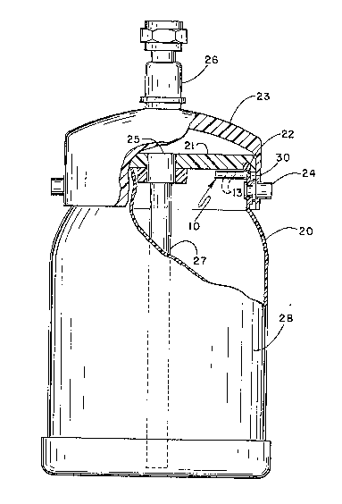
Fl~. 3 lllustrat~ onu appllcatlon of a preferred
embodlment of the lnventlon. Conventlon~lly, the open top o~ a
cup or ~ar contalner 20 l~ clo~e~ wlth a cap 21 whlch 1~ ~ealed
around the ~o~ edge of CUp 20 by an ~nnular ~eal 22 when handle or
brldg~ 23 l~ WUn~ to th~ up~l~hc ~o~ltlon ~bout l~ plvot polnt~
24 on cont~ln~r 20. A no~ma1 ~utl~ oponln~ 25 ~hrou~h cap 21 18
att~ch~d to ~ ~lttlng 26 whlcl) ~xt~nd~ ~bovo the c~p and a tube 27
~hlch ~xt~ndd downw~rd lnt~ ~h~ 1lqult 28. A ~ray ~un, not
shown, 1~ norm~lly ~tt~oh~ t~ th~ upp~r ~nd of fl~tlng 26.
Con~aln~r 20 ~y h~v~ a1r v~nt op~nln~ 30 ~u~t below the
~ealed c~p 21. U~d ~0 ~ n cu~, conven~lona11y when the
~pray vun 18 trl~r~d, ~lr ~ L om t1)u ~ nt a~mo~phere lfi dr~wn
throu~h v~nt openlnu 30 ln~o t~l~ ln~erlo~ o~ contalner 20 and the
.
. -. : ,
.
:.
llquld 28, whlch ty~lcAlly m~Y b~ p~lnt, 1~ drawn up thrGugh tube
27 and ~lt~ln~ 26 and ~pr~d through ~ nozzle ln the attached
~un. Conv~ntlon~lly th~ ~un 1N ~uppllod wlth pro~url2ed alr from
a sultAbl~ ~oura~ to ~ n ll~uld out ~ c~p 2Q ~nd ~lr 1~ drawn
from ~h~ ~tmo~ph~ lnto Y~t ~nln~ 30- I~ t~ oper~tor ~hould
tllt th~ cup 20 too ~r, o~ lt lt u~ould ~t knocked over, ~ome of
the llquld 2~ ~rdln~rlly wo~ 111 out of vent opunlnq 30. To
prevunt thlu, Antl-~plll~ duvla~ lO, ~uch ~ lllu~trated ln
Fl~. 1 4nd 2, 18 att~ched ln~lda the cu~ 20 to the vent openln~
30. Durlna normal operAtlon ~lr i~ allowad to enter the cup
lnterlor qulte fr~ly fro~ th~ out~lde ~mblent ~tmo~phere through
vunt openln~ 30 but ln tha ev~nt ~h~ con~lner ~hould be tllted
too ~ar or knock~d ov~r ~o th~t th~ lev~l of ehs llquid reaahes
the level o~ th~ al~ vent op~nlng, the ~oreen~ ~revent the reverie
flow of llquld 2~ out throu~h ~1~ vent 30.
In the Cd~ wh~r~ tho hlr vent openln~ 30 16 through cap
21 of contalner 20, as lllu~rated ln F1~. ~, one end of tubin~ 11
cont~lnln~ ~creen~ 13, as lll~tra~ed ln Fl~. 1 and 2, may be
attached lnt~rnally to the vent openln~ ~not shown) ar may be
attached by a 6ultable flttln~, ~ener~lly de6~nated by reference
numeral 31, to v~nt op~nln~ 30 outulde contalner 20. Amblent alr
1~ permltt~d to flow rel~tlv~ly t~ely lnto the lnterlor of
cont~ln~r 20 bu~ 11quld rrom ~h~ contaln~r wlll ba prevented rom
s~lllln~ onto th~ ~round Q~ o~hur work ~r0~ throu~h v~nt openlng
30 should ou~ 20 b~ tl1t~d to~ ~r or tov~le ovor. In ~ome ~pray
~un ~pllc~tlon~, ln~t~nd o~ oun ~r01y ~lphonln~ llquld out
of tho cont~lner, iow ~r~aur~ ~lr 1~ ~pll~d through tublng 11
lnto ~he lnte~Lor of cup 2Q tilrc~uU~ v~n~ opanlng 30. The
,
. 7
an~ e devlc~ ~tt~ch~d to eubln~ llA th~n functlon6, a~
descrlbed, to ~revenC ~low of llquld out of vent openlng 3~
throu~h tube 11 ~ack to th~ pr~ur~ ~ource throu~h tube llA ln
tha ~vent th~ cont~lnur 1~ ~llt~ too ~r or fall~ over whlle ~he
~lr pr~ uF~ ~our~ turn~
~ hll-- a ~", U~ .J t-. ~, lv-~ a rl~aorou~ 0alent~flc
explanatlon for ~ dntl-~p~ And ~ntl-drlppln~ phenomenon
that occUr~ appudr~ th~t ~ n t~ llquld reacha~ and we~6 the
~creen~, lt 1~ p~ev~nt~d rom contlrluln~ to ~low ~hrou~h the tube
past the ~creen~ by the ~ntrAplnant of ~ome of the llquld between
two ad~acent ~creen~ evun lf the ~creonn ~re very clo~e or
touchln~ one ~nother.
In tha ~ppllcatlon~ illu~trated ln Fl~. 3 and 4, ln the
ca6~ ln whlch low pr~Ur~ alr 1~ a~pll~d lnto ~he cup ~hrou~h
tube 11 ~nd vent ~nlna 30, ~un~rdlly th0 llquld whlch i~ trapped
by the ~cr~n~ wh~n th~ b~url2~d ~lr l~ ~urned off wlll be
forced b~ck lnto t~ cont~lner wh~n tho pre~urlzed alr come~ back
on or may otharwl~e flow ba~k lnto the contalner by ~lltln~ the
contalner. ~owev~r, lt 1B prudunt that the lntorlor of the tube
and the ~creen~ be c1qaned qulte promptly a~ter u6e to prevent the
trapped 1lyuld, ~uch a~ ~lnt. ~rom dryln~ u~ wl~hln th~ tube
and/or on the ~cr~en~ whlch could lm~ the ~lr 10w. ~l~o, lt
may be n~c~uary ~rom tlm~ to tlm~ to r~mov~ u~ed ~creen~ and
replace th~m wlth n~w or n~ly cl~n~d sc~ens.
In ~noth~r Ap~ tlun, ~ Fl~. 5, a condul~ 33 ~uch a~
~ ho~ or ~ y ~lorn~a11y ~ u~d ~or c~rrY1n~ llquld trom a
reservolr 3~ pr~uurlz~d by ~ 5 to An outlet o~enln~ 36. ~wo
or more ~c~nD 13 of th~ n~t~r~ d~acrlbud huruln when ~laoud
. . :
: .
'
:
.
' . ' ' : ~
8 2~
aCrOa~ tht3 11~U1d 10W ~th ll~gr ~he ~P~n OUt1~t end 36 a110W the
Pre~U~1Z~ U1d tO ~1DW qU1te ea~11Y thXOU~h and OUt the OUt1et
Ut Wh~n the Pr~ Ur~ 1~ r~mOV~, 1.e., PUmP 35 tUrned Off,
the flow l~ ~opp~d l~nedlat~ly by ~areen~ 13 ~hereb~ s11mlnatlna
drlppln~ ~t th~ ~utl~t ~nd 3~
In ~dltlun to ~ t~ut ~ntlonu~ e~rllar h~relnabove,
two ~a~ vll~ ut ~ hr lno~l. o~ ~bout .C024 lnch
openln~, m~de ~rom ~ln~ ~oly~ r t~r~d~ pl~ced clo~e to the
bOttOm 0~ ~ forty-two ln~h lon~. thro~-~u~rtar lnch I.D. v~rtlca1
tube held b~ak up to o1~vun lnch~ o~ w~twr ~nd ll~uld late~ palnt
havln~ ~ ~paclfla ~r~vlty of about 1.3~ up to th~ maxlmum o~
forty-two lnahe~ a r~ult oP the~ te~t~, lt appeax~ that for
each ~pp1lc~lon ~ome de~r~ of ~xp~rlmant~tlon may be neceasary
to det~rmlne th~ screen m~h ~lz~, tub~ ~lze (I.D.), the number of
~creen~ and, p~rh~p~, ~h~ ~pacln~ butws~n ~creen~ to obtaln be~
~eu1t~.