Note : Les descriptions sont présentées dans la langue officielle dans laquelle elles ont été soumises.
2016~06
2l-DSV-2720
CONTROL SYSTEM FOR LOW SPEED SUITCHED RELUCTANCE HOTOR
BACKGROUND OF THE INV~NTION
This invention relates generally to motor
controls and, more particularly, to a control system
and method of control for a switched reluctance motor.
Switched reluctance motors conventisnally have
multiple poles or teeth on both stator and rotor,
i.e., they are toubly salient. There are phase
windings on the stator but no windings on the rotor.
Each pair of diametrically opposite stator poles is
connected in series to form one phase of a multi-phase
switched reluctance motor. Torque is produced by
switching current into each of the pha~e windings in a
predetermined sequence that is synchronized with the
angular position of the rotor, so that a ma~netic
force of attraction results between the rotor and
stator poles that are approaching each other. The
current is switched off in each phase before the rotor
poles nearest the stator poles of the phase rotate
past the aligned position. Otherwise, ~he magnetic
force of attraction would produce a negative or
brakinB torque. The torque developed is independent
of the direction of current flow so that
unidirectional current pulses synchronized with rotor
movement can be applied to develop torque in either
2~16~6
21-DSV-2720
2 --
direction. These pulses are ~enerated by a converter
usin~ current switching elements such as thyristors or
transistors.
In operation, each time a phase of the switched
reluctance motor is switched on by closing a switch ih
a converter. current flows in the stator windin~ of
that phase, providing energy from a direct current
(DC) supply to the motor. The enersy drawn from the
supply is converted partly into mechanical ener~y by
causin~ the rotor to rotate toward a minimum
reluctance configuration and partly in stored energy
- associated with the ma~netic field. After the switch
is opened, part of the stored magnetic ener~y is
converted to mechanical output and part of the ener~y
is returned to the DC source.
U.S. Patent No. 4,707,65~ describes a control
system for a switched reluctance motor employing a
programmable, closed loop, four quadrant control
system incorporating feedback control, angle control
and current control. The feedback control
incorporates a speed feedback loop and/or a torque
feedback loop. The angle control digitally
synchronizes stator phase current pulses with rotor
position, and the current control acts as a chopping
or bang-bang controller to limit the magnitude of the
stator phase current pulses. The magnitude and turn-
on and turn-off angles of the stator current pulses
for each phase, in feedback mode, are controlled so as
to provide s~ooth operation and full torque ant speed
ran8e with optimum periormance in all four quadrants
of motor operation, i.e., forward motoring. forwart
braking, reverse motorin8 and reverse brakin8.
2~16~)0~
21-DSV-2720
-- 3
The closed loop feedback control processes an
actual motor speed signal and an operator command to
Benerate a current command. which serves to limit
magnitude of actual phase current, and also generates
a turn-on angle signal and a pulse width angle signal
which are coordinated with a particular quadrant in
which the motor is operating. The values of turn-on
angle and pulse width angle are programmable for
different quadrants of operation. For motoring
guadrants, the turn-on angle signal is directly
proportional to the current command while the pulse
width angle signal is a function of the current
command and actual motor speed.
The digital angle control processes rotor
position information signals to 8enerate a multi-phase
sync pulse train and individual stator phase signals
for the respective stator phases. The angle control
also generates a resolution si~nal with the desired
angle resolution. The angle control employs the
resolution signal and the individual stator phase sync
signals to convert a turn on angle signal and a pulse
width angle signal into corresponding current pulses
synchronized with rotor position for each of the
stator phases.
The current control compares the current command
from the feedback control with actual current in each
stator phase to Benerate a current magnitude limiting
signal and couples ~his signal with the pulse train
for each phase from the angle control to 8enerate the
stator current control pulses applied to the switching
elements in the motor power converter.
While the disclosed system provides for suitable
control of a switched reluctance motor, it is believed
2V16~0~
21-DSV-2720
4 --
that further improvement and operation can be attained
over a relatively broad low speed range, e.g., for
speeds up to about 16,000 rpm, by providin~ a control
system which assures that winding current reaches its
commanded set point value at a commanded angle. This
desirable feature, which was addressed in one for~ in
the aforementioned U.S. Patent No. 4,707,650, is
important to the operation of the switched reluctance
motor over a wide speed range because the counter
electromotive force (CEMF) in the motor is a function
of the angular velocity of the rotor of the motor.
For example, with the same set of turn-on and turn-off
angles at hi8her speed, the CEMF is positive in
polarity at the beginnin~ of a current pulse, thus
opposing the injection of current into the winding,
while the end of the current pulse may extend past the
ali8nment position causin~ the CEMF to become negative
in polarity and forcin~ current to be retained in the
winding. The amount of delay in the current pulse
reaching its desired value is a function of current
level, speed, position of the current pulse and DC
source voltage. The effect, given a fixed set of
turn-on and turn-off angles, is to greatly reduce the
amount of motoring torque that can be produced as
speed increases thus causin~ the torque, as a function
of current, to become a strong function of motor
speed.
2~16~
21-DSV-2720
- 5 -
SUMMARY OF THE INVENTION
It is an object of the present invention to
provide an improved control system for a switched
reluctance motor, which system controls current pulse
timing over wide speed ranges.
The present invention overcomes the above and
other disadvanta~es of the prior art systems by
incorporating an advance angle regulator which
establishes the firin~ angle of current pulses to the
switched reluctance motor so that over a wide ran8e of
speeds and levels of direct current source voltages,
the winding current reaches the commanded set point at
a commanded angle. In a preferred form, the advance
an~le regulator comprises a closed loop re~ulator
utilizing both hardware and software controls. In
this embodiment, the position of the rotor is provided
by a resolver in a manner disclosed in the
aforementioned U.S. Patent No. 4,707,650~ A
comparison subsystem in the regulator compares a
signal proportional to the phase current in the motor
with a phase current reference. ~hen the phase
current first reaches the level of the reference, a
state change is detected by the comparison subsystem
and utilized to retain the rotor angular position at
the instant that the phase current reached the
reference value. This information is then used in a
feedback control system to adjust the turn-on and
turn-off angles to assure that current reaches the
commanded value at the commanded angle. Reset
circuitry is provided to reset the comparison
subsystem after the present current pulse reaches a
zero value. This assures that the rotor position
`` 2~16~0~
2l-DSV-2720
-- 6 --
which is latched by the comparison system is a first
position at which the current reached the reference
level during the monitored current pulse. In this
system, the position feedback can be obtained at any
time during the current pulse and allows the advance
angle regulator to continuously adjust the turn-on
angle and turn-off angle to the optimum values.
The advance angle re~ulator, in an illustrative
embodiment, incorporates a feed forward portion and an
integral portion. The integral portion includes
clamps and a rate limit to limit the excursion and
rate of change of signals in that portion of the
regulator. The feed forward portion is desirable at
hiBh speeds to avoid a condition that might occur if
switching occurs at hi8h current levels so as to
eliminate feedback available to the integral plus
portion of the circuit. For example, there may be no
feedback if the current does not reach the commanded
set point during a current pulse. The feed forward
portion is helpful at low speeds to improve the
dynamic response of the regulator by preticting the
rise time of the current pulse.
In the pr~ctice of the present invention, control
of the phase current pulses is accomplished by first
selecting the optimum turn-on and turn-off angles at
very low speed where the current rise time is
negligible. These angles are then fixed throughout
the entire speed range. The output of the advance
angle regulator is a position adjust angle which is
combired with the optimum turn-on and turn-off angles
at speeds where the current rise time is significant.
In this manner, the advance angle regulator assures
that the current reaches its set point at the optimum
2~16~0~
2l-DSV-2720
-- 7
angle. The regulator causes the torque versus current
command to have a transfer function which does not
depend upon speed or DC source voltage over a wide
ran~e of speed. voltage and torque.
5BRIEF DESCRIPTION OF THE_DRA~INGS
The foregoing and other objects, features and
advanta~es of the present invention will be apparent
from the followin~ detailed description of the
invention when read in conjunction with the
accompanyinB drawin~s in which:
FIG. IA is a schematic representation of a
typical switched reluctance motor;
FIG. lB illustrates a typical power converter for
the switched reluctance motor of FIG. lA;
15FIG. 2A ~rofiles inductance with respect to rotor
angular position for a stator pole pair of the motor
of FIG. lA;
FIGS. 2B and 2C illustrate typical stator phase
current pulses for forward motoring and reverse
motoring, respectively:
FIG. 3 is a simplified functional block dia8ram
of a switched reluctance motor control system in
accordance with the prior art with which the present
invention may be uset;
25FIG. 4 is an illustration in block dia~ram form
of a typical prior art method and apparatus for
- 8eneratinB a current command from motor speeds: and
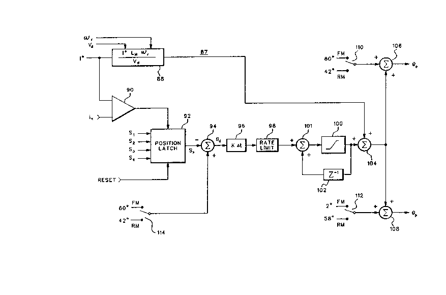
FIG. 5 is an illustration in block dia~ram form
of an advance angle regulator in accordance with the
present invention.
2~16~6
21-DSV-2720
-- 8 --
DETAILED DESCRIPTION OF THE INVENTION
FIG. lA is a schematic representation of a
typical switched reluctance motor 10 including a rotor
12 rotatable in either a forward or a reverse
direction within a stator 14. The forward direction F
indicates counterclockwise rotation of the rotor while
the reverse direction R indicates clockwise rotation.
Rotor 12 has three pairs of diametrically opposite
poles labeled a-a', b-b' and c-c'. Stator 14 is
provided with four pairs of diametrically opposite
stator poles labeled A-A', B-8', C-C' and D-D'. For
purpose of discussion, the motor lO is assumed to be
constructed such that each rotor pole and each stator
pole has an angular extent of 1~. The
circumferential spacing or gap between adjacent rotor
poles in this embodiment is 42 while the gap between
adjacent stator poles is 27. These angles are
measured with respect to center point 0.
The opposite poles of each stator pole pair share
a common winding and define a respective stator phase.
A representative winding coil 16 for phase A is
illustrated in FIG. lA. Similar windings are provided
for each of the other stator pole pairs.
Rotor rotation is produced by switching current
on and off in each stator phase winding in a
predetermined sequence synchronized with angular
position of the rotor. Current in each stator phase
is derived from power converter 20 of FIG. lB, which
impresses a DC link volta~e Vd across the four
parallel stator phase legs PH-A, PH-B, PH-C and PH-D.
Link voltage Vd can be obtained from a battery (not
shown), or from an AC power supply, e.g., three phase,
2~16~0~
2l-DSV-2720
_ g _
220 volt, 60 Hertz line, through a conventional diode
rectifier circuit 22 and filterin~ capacitor 23.
The converter circuitry for each stator phase leg
is identical. The PH-A leg, for example, includes a
stator winding 24A, first and second flyback diodes
26A and 26A' and first and second current switching
devices such as transistors 27A and 27A'
interconnected as shown in FIG. lB. A base of each of
the transistors is connected to an output of the
current control 48.
When transistors 27A and 27A' are switched on, a
phase current Ia~ derived from link current Id flows
through the stator winding for phase A. When the
transistors 27A and ~7A' are switched off, current in
the winding 24A decays by re-circulating to the source
or to the filter capacitor 23 through the flyback
diodes 26A and 26A'. During braking, a dynamic brake
transistor Tdb in series with a resistor R across the
rectified AC source is switched on to dissipate
recovered energy in resistor R rather than
transferring it into capacitor 23. Alternatively.
with a battery power supply, the energy could be
absorbed by the battery. A signal, ia~ representative
of phase current, Ia. is 8enerated by any suitable
means 25A, such as a shunt or a current transducer
such as that commercially provided by Liaisons
Electroniques Mechaniques S.A. of Geneva, Switzerland.
The converter circuitry for each of the other
phase legs operates identically and accordingly is not
detailed herein. The transistors coupled in series
with each of the phase windin~s are made to conduct in
sequence, with the order of conduction depend;ng upon
the direction of rotation. In the illustrative
2~16006
21-DSV-2720
-- 1 0
embodiment, a particular phase is fired periodically
with a cycle period of 60 with respect to rotor
position and~ therefore, for the four phase machine,
consecutive phases are fired at 1~ intervals. The
S timin~ and wave shape of stator phase current pulses
for different quadrants of operation are shown in
FIGS. 2A-2C. The inductance profile of a stator pole
pair, e.g., phase A, with respect to rotor angular
orientation is shown in FIG. 2A, while typical stator
phase current pulses for the various quadrants are
illustrated in FIGS. 2B-2C. The inductance profile
has a cycle period ~cy equal to 60 and the
distribution of rising inductance, falling inauctance
and minimum inductance periods, for both forward and
reverse direction rotations and reference frames. is
shown in FIG. 2A. For forward rotation, the
inductance increases for the first 18. At 18, a
rotor pole is alisned with a stator pole and peak
inductance Lp is achieved. From 18-36, the
inductance falls and for the next twenty-four degrees
remains at a minimum inductance Lm~ then the cycle
repeats. For reverse rotation, the inductance falls
from 0 to 18, remains at a minimum inductance Lm
from 18 to 42, and then rises to the peak inductance
2~ Lp from 42 to 60.
Examining FIGS. 2A and 2B, it will be seen that
in a forward motoring (FM) quadrant, the stator
current pulse 28 is established where the inductance
profile has a positive slope. Current I is switched
on at a turn-on angle ~0 and rises linearly to the
ma8nitude of I at the corner point (0) of the
inductance profile. Current I is maintained
substantially constant by choppin~ or bang-bang
2~16~0~
2l-DSV-2720
I I
control and is controlled such that I is essentially
equal to the commanded current I*. The transistor
cwitches coupled in series with the winding 24 are
switched off at a turn-off angle ~p. which is a few
degrees ahead of the peak inductance Lp point. so that
the angle eq~ at which the current reaches zero.
occurs only slightly into the negative inductance
slope region. A pulse width angle ~pw extending from
the transistor turn-on an6le ~0 to the transistor
turn-off angle ep is shown in FIG. 2B.
As actual speed ~rr increases. angle ~0 and ~q
expand or spread apart from each other. but the pulse
width angle ~pw remains unchanged. as shown by pulse
in FIG. 2B. At hi8h speed, the machine CEMF
exceeds the DC supply voltage ant bang-bang current
control is lost. The expansion of angles ~O and ~q is
controlled to optimize torque production.
As shown in FIG. 2C. current pulse wave shape 29,
at low speed. and 31. at hi8h speed. in reverse
motorin~ (RM) are identical to those in iorward
motoring. except that they are reversed in direction
and occur during the opposite slope of the inductance
profile. which appears as a positive slope in the
reverse direction.
The basic control parameters of the switched
reluctance motor drive system can be summarized as
follows:
I i5 the chopping current level;
is the transistor turn-on angle:
~p is the transistor turn-off an~le: and
~pw is the difference between eO and ~p.
2~16~0~
21-DSV-2720
- 12 -
Referrin8 now to FIG. 3. there is shown asimplified functional block dia8ram of one form o'
control system for a switched reluctance motor with
which the present invention may be advanta~eously
used. The basic control system includes feedback
control block 44, angle control block 46. and current
control block 48. In addition. a start-up control
block 50, an absolute rotor position encoder block 52.
an incremental position encoder block 54 and a speed
calculator block 56 are included.
Feedback control block 44 may comprise a speed
loop. a torque loop or a speed loop with an inner
torque feedback loop. As illustrated, FIG. 3
incorporates a speed loop. The feedback control
receives an operator command. e.g.. speed command ~rr*
and an actual speed signal~r from speed computation
block 56. The closed loop feedback control processes
the operator command and actual speed si~nal to
Benerate a current command I*. a turn-on angle signal
eO and a pulse width angle signal 4pw The values of
the turn-on angle and pulse width angle si~nals may be
independently programmable for different quadrants of
operation. For example, the turn-on angle si~nal may
be made directly proportional to the current command.
and the pulse width angle signal or turn-off angle
signal is made a function Or the current command and
actual motor speed. A detailed description of one
form of implementation of feedback control 44 may be
had by reference to the aforementioned U.S. Patent No.
4.707.650.
Angle control 46 receives the turn-on an~le
signal eO and the turn-off or pulse width 2ngle si~nal
epw from feedback control 44. and rotor position
.
2~6~0~
21-~SV-272
- !3 -
:...o-~.atios ~i ~n~l 6 S~ ~ S~, S3 ~ S~ '~om er. oc~. '2
1~e ~r.6!b cor~ro~ ci~itsl~! rrcce~es ~eG~ s:6^.~!6 -o
,rovide mutu~lly phfise ~h1~ted ?u~e ~rsins 'or the
cj~ferent st~tor pha~es, each pulse t^_in compri G i r~8
co~ductior, an61~ pul3e~ synchro~ized ~l~h ~he ro~or
?03i~lon snd coordin~;~d with ~n i~uc's~ce prc'11e o~
~he motor in ~ccord~ncc ~ith the ~loct~d quaArcn~ o'
motor operstion.
Current control 4~ receiv~ tho currcnt commPn~
1~ ~rom ~ce~bsck control 44, ~he ~c-u81 curr~n~
reprosentatlve ~;Onals 1a~ ib, ~c ~nd id
rtator phace, ~nd the pulse tr~ins from ~n61e con.rol
4~. The curren' control proces~os thcse siEnals ~o
provlde s~ltchin~ control ~i6n~1~ SA-Sa ~ SD-Sb ~ Sc~
Sc', Dr,~ Sd-Sd' to the b~so terminalc of tr~nslstor
pair~ such as, ror excmplo, tr~nBI~tor pair 27A ~nd
27A' in FI5. ~B. The currsnt control prc'erably
opora,es on ~ ba~-b~n6 control principle and 6e. voe
~o m~ ntain ~m~ ude c' ~ctu~l ^urrer,: lr. e~ch s'~tsr
~hacc ~ithin the hyst~resis bar,a c~ 'he cu,ren~
^c~.~.ar.d, U? ~c 9 bas~ mcto. s?ecd, nd l!m,t 5 pe~k
ar,?li~uce o~ sctual c~r,~nt in ~ach s~a~o. phase 'o
:h~ ~x.mum v~lue o, ~ne hy~teresis ban~ beyor.~ 'he
base ~p~od.
2- The contro! syste~ prerena~ly lrclud~s ~ s'~r~e,
ccntrol 50 ror ~nitla~rO r o.c. ro;~tion. One ex6mple
o' ~ ~t~rt-up cor,~ro' is s.~o\-. in U.~. ~z;sn~ No.
4,713,59~ entitied ~S~fr~ ? Contrcl For S~itch
~eluc:znce Mctor~ Dy B.X. ~06~ ani P.~. S'^zeEny.
3Q Abso!uto ro'or po~!~lon encode. 52 provides
posltion ir.rormation s,~n~ls ~I-S~, inr!ca',ve o,'
1nst~ntzneou~ ro~o. ?~s-tiAJn~ ~O, pu!Ee
s;~nohron~z~tion purposes. ~o ~n~le con'rol ~ ar.d
2~16~06
21-DSV-2720
- 14 -
start-up con'rol 50. The same rotor position
information signals can advantageously be processed by
speed calculator 56 to 8enerate the actual speed
si~nal ~rr
A complete description of the operation of the
control system of FI~. 3 is set forth in U.S. Patent
No. 4.707~650. The present invention provides an
improvement to the feedback control block 44 to
provide more accurate and better tracking of the ~0
and ~pw angles for providing turn-on and turn-off
commands to the an~le control block 46 during forward
and reverse motorin8- Before describin8 an
implement~tion of the present invention. reference is
first made to FIG. 4. where there i illustrated a
speed control loop 60 which can be used to implement
feedback control 44 of FIG. 3. The control loop 60
includes a summation circuit 82 for comparing a speed
command Wr* with actual speed~r and 8enerating a
speed difference signalz~d therefrom. Speed command
~Sr* is operator input while the actual speed is
calculated by speed calculator 56 from rotor position
information signals provided by either absolute
encoder 52 or incremental encoder 54 as was described
with reBard to FIG. 3. This speed difference si~nal
from summation circuit 82 is processed by a
proportional plus inte~ral compensator 84 and absolute
value circuit 86 to produce current command I*. The
speed difference signal is also app!ied tO the
ne~ative input of a polarity detector 88. the positive
input of which is ~rounded. The output signal of
polarit~ detector 88 is used to differentiate between
motoring quadrants and generation quadrants and may be
employed to coordinate turn-on and pulse width anglçs
2~16~06
21-DSV-2720
- 15 -
with motor operating quadrants. Currer.t command I~ isprovided to the current control 48 as shown in FIG. 3.
In accordance with the present invention, the I*
current command signal is also supplied to an advance
angle regulator 87. that is, a eO and ep computation
subsystem illustrated in block dia8ram form in FI~. 5.
In the advance angle regulator, the current command I*
is compared with a phase current reference ix (which
may be ia~ ib, ic or id) in a comparator 90 to
determine when the phase current first reaches the
commanded value. In the preferred embodiment, a
single phase current ix is shown with a single
comparator and is all that is necessary because the
other phases will follow due to the fixed an~ular
relationships of the rotor and stator; howeve,, it
will be reco~nized that this may represent current in
each of the phases of the multi-pole motor illustrated
in FIG. 1, with the current in each phase beinB taken
one at a time for comparison to the current command
signal I*. When the phase current ix reaches the
reference value I*, the comparator 90 changes state
causing a latch 9~ to retain the rotor position as
indicated by the encoder signals S1-S4 so that a
record is obtained of the rotor position at the
instan~ that the phase current reached the commanded
value, A reset signal is provided to insure that the
rotor position which is latched by the latch 92 is a
first position at which the current reaches the
reference level established by the I* signal. The
reset signal resets the latch, or clears the latch,
after the current pulse in the presently monitored
phase reaches zero and may be Benerated from the angle
control block 46 of FIG. 3 at the turn-off angle ep.
2016~6
2l-DSV-2720
- 16 -
The specific implementation of connections to monitor
the current pulse in each of the phases of the
switched reluctance motor is well known in the art and
is not shown in FIG. 5.
The latched position at which the phase current
ix reaches the commanded value I~ is compared with the
turn-on angle set by the characteristics of the system
at low speed. For example, for thç illustrative
motor, the angle is set at 60 as shown in FIGS, 2A-2C
and this position is compared with the position stored
in the latch 92. Any difference in the two positions
results in an error signal when the two signals are
summed-in summin8 junction 94, The difference sisnal
from summing junction 94 is indicated as ed.
The advance angle resulator 87 has t-wo basic
parts, a feed forward portion and an integral portion,
The integral portion is illustrated by bloc':s 96, 98,
lO0 and 102. The feed forward portion is illustrated
by the block 88. The feed forward portion 88 has been
found to be advanta~eous at hi~h speeds when the
commanded current is at relatively hiBh values, At
that time, there may not exist any feedbacK available
to the integral portion since the actually monitored
phase current ix may never reach the commanded current
value I*. At lower speeds, the feed forward portion
88 improves the dynamic response of the regulator by
predicting the rise time of the current in each phase,
For example, the rise time can be shown to be equal to
the commanded value of phase current I* times the
minimum inductance Lm of the phase measured at an
unaligned rotor position multiplied by the angular
velocity ~r of the rotor and divided by the source
voltage DC level, Vd. In per~^orming this calculation.
2~16~06
21-DSV-2720
- 17 -
the block 88 approximates the rise time of the currentbased on the assumption of constant minimum inductance
and no CEMF~ The actual rise time will be appreciated
to be longer than the ideal value and is therefore
compensated for by the integral portion of the system
of FIG. 5. The blocks 96, 98 and 102 constitute an
integral resulator. althou~h a proportional plus
integral regulator could be used, both of a type well
known in the art. The particular embodiment
illustrated is that implemented by a di8ital
microprocessor. It will be recognized by those
skilled in the art that an analog implementation could
be constructed and that the functional blocks may be
modified accordingly. The 8ain of the integrator i5
developed by the block 96 which multiplies the ed
si~nal by the product of the desired gain and a sample
time, ~ t. The rate limit block 98 limits the rise
time of the signal from the block 96. The block 100
places an upper and lower clam? on the amplitude of
the signal to limit its excursion during transients.
Block 102 constitutes a one-sample delay, the output
of which is the previous output of block 100 which is
summed in block 101 with next occurring data. The
output of the integral portion of FIG. 5 is summed at
summins junction 104 with the feed forward signal from
block 88. The resultant an~ular position adjust
signal is then summed in block 106 with the
preselected optimum turn-on angle position to produce
the final compensated turn-on an~le ~0. Similarly,
the signal from summing junction 104 is summed in
another sum~ing junction 108 with the preselected
optimum turn-off an~le to produce the compensated
turn-off angle ~p. As indicated schematically by
2~16~06
21-DSV-2720
- ~8
switches 110. 112 and 114. the turn-on angles may be
selected to be different angles for forward motoring
(FM) or reverse motorin8 (RM).
The phase current pulses are thus controlled by
selecting the optimum turn-on (eO) and turn-off (~p)
angles at very low speeds where the current rise time
is negligible. These an~les are then fixed throu~hout
the entire speed range of the motor as shown in 110
and 112 of FIG. 5. The output of the position adjust
system of FIG. 5 developed at an output terminal of
summing junction 104 is added to these optimum turn-on
and turn-off angles at speeds where the current rise
time is significant. The closed loop regulation of
the position at which the phase current actually
reaches the commanded value assures that the current
reaches its set point at the optimum angle. By using
this advance angle regulator, the torque versus
current command has a transfer function that does not
depend upon speed or DC source voltage over a wide
range of speeds, volta~es and torques. In other
words, the machine output torque is a function of the
current command and becomes essentially invariant with
changes in speed or voltage.
Uhile the invention has been illustrated in a
functional block diagram in FIG. 5. it will be
appreciated that the invention may be implemented in
either a microprocessor based programmable control or
in a hardware based design. Uhile the invention has
been described in what is presently considered to be a
preferred embodiment, it will be obvious to those
skilled in the art that numerous variations, changes
and modifications can be made in the system without
2~16~
21-DSV-2720
19 _
departin8 from the invention. Accordingly. it is
intended that the invention be limited only by the
spirit and scope of the appended claims.