Sélection de la langue

Search

Sommaire du brevet 2018740 

Énoncé de désistement de responsabilité concernant l'information provenant de tiers

Une partie des informations de ce site Web a été fournie par des sources externes. Le gouvernement du Canada n'assume aucune responsabilité concernant la précision, l'actualité ou la fiabilité des informations fournies par les sources externes. Les utilisateurs qui désirent employer cette information devraient consulter directement la source des informations. Le contenu fourni par les sources externes n'est pas assujetti aux exigences sur les langues officielles, la protection des renseignements personnels et l'accessibilité.

Disponibilité de l'Abrégé et des Revendications

L'apparition de différences dans le texte et l'image des Revendications et de l'Abrégé dépend du moment auquel le document est publié. Les textes des Revendications et de l'Abrégé sont affichés :

  • lorsque la demande peut être examinée par le public;
  • lorsque le brevet est émis (délivrance).
(12) Brevet: (11) CA 2018740
(54) Titre français: FUSION DU VERRE
(54) Titre anglais: GLASS MELTING
Statut: Périmé et au-delà du délai pour l’annulation
Données bibliographiques
(51) Classification internationale des brevets (CIB):
  • C03B 05/03 (2006.01)
  • C03B 03/02 (2006.01)
  • C03B 05/04 (2006.01)
  • C03B 05/185 (2006.01)
  • C03B 05/20 (2006.01)
  • C03B 05/225 (2006.01)
  • C03B 05/24 (2006.01)
(72) Inventeurs :
  • TREVELYAN, ROBERT EMMETT (Royaume-Uni)
  • WHITFIELD, PETER JAMES (Royaume-Uni)
(73) Titulaires :
  • PILKINGTON PLC
(71) Demandeurs :
  • PILKINGTON PLC (Royaume-Uni)
(74) Agent: FINLAYSON & SINGLEHURST
(74) Co-agent:
(45) Délivré: 1999-03-30
(22) Date de dépôt: 1990-06-11
(41) Mise à la disponibilité du public: 1990-12-13
Requête d'examen: 1994-02-10
Licence disponible: S.O.
Cédé au domaine public: S.O.
(25) Langue des documents déposés: Anglais

Traité de coopération en matière de brevets (PCT): Non

(30) Données de priorité de la demande:
Numéro de la demande Pays / territoire Date
8913539.6 (Royaume-Uni) 1989-06-13

Abrégés

Abrégé français

Cette invention concerne une cuve de fusion de verre composée d'une enceinte de fusion, d'une enceinte peu profonde de conditionnement à flux continu, d'une enceinte peu profonde d'affinage et d'une colonne montante entre l'enceinte de fusion et l'enceinte d'affinage. Le verre fondu est chauffé dans la colonne montante par des électrodes centrées près de la base de celle-ci. Des capteurs de température déterminent la température du verre fondu pénétrant dans la colonne montante par un étranglement ainsi que sa température près de la base du muret aval de ladite colonne, et l'apport de chaleur est réglé de manière à induire dans cette colonne un flux toroïdal.


Abrégé anglais


A glass melting tank has a melting chamber, a shallow uniflow
conditioning chamber, a shallow refining chamber and a riser
chamber between the melting chamber and refining chamber.
Heat is input to glass in the riser chamber by electrodes
located centrally in the riser chamber near the base of the
riser chamber. Temperature sensors sense the temperature
entering the riser chamber through a throat and near the base
of a downstream wall of the riser chamber and the heat input
is controlled to produce torroidal flow in the riser chamber.

Revendications

Note : Les revendications sont présentées dans la langue officielle dans laquelle elles ont été soumises.


-14-
The embodiments of the invention in which an exclusive property
or privilege is claimed are defined as follows:
1. A method of forming molten glass in a glass melting
tank which method comprises heating batch material in a melting
chamber (11) to produce molten glass, refining the molten glass
in a refining zone (12) and thermally conditioning the glass
prior to causing the glass to flow continuously through an
outlet from the tank, said method being characterized by causing
the molten glass to flow through a riser chamber (14) between
the melting chamber (11) and the refining chamber (12), the
glass entering the riser chamber (14) through a throat (23) at
the base (26) of the riser chamber and leaving the riser chamber
through an outlet (39) at its upper end, the glass being heated
in the riser chamber (14) in a central zone spaced from the
walls (28, 29) of the riser chamber while cooling upstream and
downstream walls (28, 29) of said riser chamber whereby an
inhomogeneous temperature distribution is formed in the glass
across the riser chamber (14) and molten glass is caused to flow
upwardly in said central zone of the riser chamber with downward
glass flow adjacent said chamber walls (28, 29), the heat input
to the glass in the riser chamber (14) being such as to raise
the temperature of the glass in the riser chamber and to
maintain a glass temperature adjacent the base (26) of the riser
chamber opposite said throat (23) is above the temperature of
glass entering the riser chamber (14) through the throat (23).
2. A method according to claim 1 in which the flow
through the riser chamber (14) is toroidal with upward flow in
the centre of the toroid and downward flow around the outside of
the toroid.
3. A method according to claim 1 or 2 including sensing
the temperature of glass in said throat and sensing the
temperature of glass adjacent the base (26) of the riser chamber
opposite said throat (23).

-15-
4. A method according to claim 1, 2 or 3 in which heat is
input to glass in the riser chamber (14) by use of electrodes
(25) located adjacent a base (26) of said riser chamber.
5. A method according to claim 4 further comprising
detecting temperature of molten glass in the riser chamber
adjacent the base of the downstream wall (29) of the chamber and
controlling power to said electrodes (25) in said riser chamber
(14) in response to said detected temperature.
6. A method according to claim 1, 2, 3, 4 or 5 further
comprising detecting the temperature of molten glass flowing
through said throat (23) into the riser chamber (14).
7. A method according to claims 5 and 6 wherein power to
electrodes (25) in said riser chamber (14) is controlled in
dependence on signals from the temperatures detected.
8. A method according to claim 4 in which the depth of
molten glass in the riser chamber (14) is at least twice the
height of the electrodes (25) in the riser chamber.
9. A method according to claim 1, 2, 3, 4, 5, 6, 7 or 8
in which glass enters said refining chamber (12) at a
temperature above that of glass entering the riser chamber.
10. A method according to claim 1, 2, 3, 4, 5, 6, 7, 8 or
9 further comprising impeding forward flow of glass between
refining and thermally conditioning by use of a cooling device
(44) located in the forward flow of glass.
11. A method according to claim 1, 2, 3, 4, 5, 6, 7, 8, 9
or 10 further comprising stirring forward flowing glass between
refining and thermally conditioning.
12. A glass melting tank for continuous supply of molten
glass to an outlet at a downstream end of the tank, which tank

-16-
comprises a melting chamber (11) at an upstream end of the tank,
a refining chamber (12), characterized by a riser chamber (14)
between the melting and refining chambers, said melting chamber
(11) having heating means (17) for melting batch material to
produce molten glass and an outlet (21) for molten glass
adjacent a base (18) of the melting chamber at a downstream end
of the chamber, a throat (23) connecting said outlet to an inlet
at a base (26) of said riser chamber (14) arranged to receive
molten glass from said melting chamber, said riser chamber (14)
having an outlet (39) at its upper end coupled to said refining
chamber (12) in which the molten glass is refined, said riser
chamber having heating means (25) to raise the temperature of
the molten glass and chamber walls (28, 29) including an
upstream wall (28) adjacent the inlet from the throat and a
downstream wall (29) adjacent the outlet to the refining
chamber, together with means (35, 36) to cool both said upstream
and downstream walls and heating electrodes (25) projecting
upwardly from the base (26) of the riser chamber (14) for
immersion in molten glass in the riser chamber, said electrodes
(25) being located in a central zone of the base (26) of the
riser chamber (14) and spaced from the chamber walls (28, 29) of
the riser chamber whereby an inhomogeneous temperature
distribution is formed in the glass across the riser chamber
(14) and molten glass is caused to flow upwardly in said central
zone of the riser chamber with downward glass flow adjacent said
chamber walls and surrounding said upward glass flow, the
heating means (25) in the riser chamber (14) being arranged such
as to raise the temperature of the glass in the riser chamber
and to maintain a glass temperature adjacent the base (26) of
the riser chamber (14) opposite said throat (23) which is above
the temperature of glass entering the riser chamber (14) through
the throat (23).
13. A glass melting tank according to claim 12 in which
said riser chamber (14) has upstream and downstream chamber
walls (28, 29) spaced respectively from the melting chamber (15)
and refining chamber (12) thereby providing air spaces (35, 36)

-17-
acting as cooling means for said upstream and downstream walls
(28, 29) of the riser chamber (12).
14. A glass melting tank according to claim 12 or 13
including a first temperature detector (32) located adjacent the
downstream end of the riser chamber (14) for detecting
temperature of molten glass adjacent the base (26) of the riser
chamber.
15. A glass melting tank according to claim 14 further
comprising a second temperature detector (24) located in said
throat (23) for detecting temperature of molten glass passing
through the throat (23).
16. A glass melting tank according to claim 12, 13, 14 or
15 further comprising control means (20) coupled to said first
and second temperature detectors (24, 32) and arranged to
control power supply to said electrodes (25) in the riser
chamber so as to maintain required glass flow within the riser
chamber (14).
17. A glass melting tank according to claim 12, 13, 14, 15
or 16 wherein the heating means in said riser chamber (14)
comprise a plurality of electrodes (25) projecting upwardly from
the base (26) of the riser chamber (14) to a height not
exceeding half the depth of molten glass.
18. A glass melting tank according to claim 17 in which
the electrodes (25) are spaced from the walls (28, 29) of the
riser chamber (14) by a distance at least equal to the height of
the electrodes.
19. A glass melting tank according to claim 12, 13, 14,
15, 16, 17 or 18 in which the electrodes in said riser chamber
(14) comprise an array of electrodes (25) with at least two
electrodes spaced laterally across the riser chamber and at
least two electrodes spaced longitudinally along the chamber

-18-
(14).
20. A glass melting tank according to claim 12, 13, 14,
15, 16, 17, 18 or 19 further comprising a conditioning chamber
(13) connected to said refining chamber (14) for thermally
conditioning the glass prior to flowing through an outlet (48)
at the downstream end of the tank.
21. A glass melting tank according to claim 20 wherein
cooling means (44) are arranged to extend transversely across
the upper region of forwardly flowing molten glass adjacent an
inlet (43) to the conditioning chamber (13).
22. A glass melting tank according to claim 21 in which
said cooling means comprise a water cooled pipe (44).
23. A glass melting tank according to claim 21 or 22
further including stirring means (45) located in the path of
forward flowing glass adjacent the conditioning chamber (13).

Description

Note : Les descriptions sont présentées dans la langue officielle dans laquelle elles ont été soumises.

2~18~0
-- 1 --
GLASS MELTING
This invention relates to glass melting and is particularly
directed to glass melting tanks using electric heating.
It is well known for glass melting tanks to include a melting
chamber in which solid batch material is heated to produce
molten glass before entering a refining chamber in which the
molten glass is at a sufficiently high temperature for
refining to occur and thereby reduce defects due to impurities
or bubble in the glass. Commonly the glass passes from a
refining chamber through a conditioning zone in which thermal
conditioning by controlled cooling is effected prior to glass
leaving the tank through an outlet to a forming process. Such
tanks may be used for continuous production of molten glass
and are particularly applicable to the production of high
quality glass for use in the production of flat glass.
When solely electric heating is used in a melting chamber of
such a tank it is normal for the molten glass in the melting
chamber to be covered by a cold top of solid batch material
which is progressively melted by heat from electrodes immersed
in the glass in the melting chamber. The flow path for molten
glass from the melting chamber to a refining chamber, when
using electric melting may be through a throat located
adjacent the base of the melting chamber in order to reduce
the probability of unmelted batch material being carried with
the molten glass into the refining zone.
It is common in flame fired furnaces for the molten glass in a
refining chamber to be sufficiently deep to permit
recirculation of molten glass in convective flows so that the
upper layers of glass in the refining zone are flowing towards
a downstream end of the zone with a return flow in the lower
region of the refining chamber.

- 2 ~
It is known to provide a riser chamber after the melting
chAmher. It is also known to provide heating in such a riser
chamber. However, serious problems can arise from unwanted
corrosion of refractory walls of the riser chamber by the upward
flowing glass, particularly where the riser ch~mher is
increasing the temperature of the molten glass to a suitable
refining temperature above that of the glass entering from the
melting chamber, such as may be necessary in the production of
high quality flat glass.
It is also known, for example from Figures 1 and 2 of U.S.
Patent 4,900,337, to use electrodes in a riser chAmher forming a
conditioning chamber following a throat from a melting chamber.
However conditioning involves controlled cooling where
electrodes are used to control the rate of 1088 of temperature
of the molten glass rather than raising the temperature above
that of the glass leaving the melting chAmher. Where the
temperature is not raised after passing through the throat into
the riser the problems of corrosion in the riser are less severe
due to the lower temperatures employed. Such arrangements where
the glass temperature is not increased after leaving the melting
chamber are more suitable for m-k; ng glass for containers or
fibre glass but may not provide the necessary refining for high
quality flat glass production such as that used for a float
glass production line.
Accordingly the present invention seeks to provide an improved
gla~s melting tank and an improved method of melting glass which
reduces the problem of corrosion in a riser chamber, where glass
temperature is increased after leaving a melting chamber. Such
arrangements may be used for the production of high quality flat

- 3
glass.
The present invention provides a method of forming molten glass
in a glass melting tank, which method comprises heating batch
material in a melting chamber to produce molten glass, refining
the molten glass in a refining zone and thermally conditioning
the glass prior to causing the glass to flow continuously
through an outlet from the tank, said method further comprising
causing the molten glass to flow through a riser chamber between
the melting chamber and the refining chamber, the glass entering
the riser chamber through a throat at the base of the riser
ch~her and leaving the riser chamber through an outlet at its
upper end, the glass being heated in the riser chamber in a
central zone spaced from the walls of the riser chamber while
cooling upstream and downstream walls of the riser chamber
whereby an inhomogeneous temperature distribution is formed in
the glass across the riser chamber and molten glass is caused to
flow upwardly in said central zone of the riser chamber with
downward glass flow adjacent said chamber walls, the heat input
to the glass in the riser chamber being such as to raise the
temperature of the glass in the riser chamber and to maintain a
glass temperature adjacent the base of the riser ch~her
opposite said throat which is above the temperature of glass
entering the riser chamber through the throat.
Preferably the flow through the riser chamber is toroidal with
upward flow in the centre of the toroid and downward flow around
the outside of the toroid.
Preferably the method includes sensing the temperature of glass
in said throat and sensing the temperature of glass adjacent the
base of the riser chamber opposite said throat.

- 2?~40
'' -
Preferably heat is applied to glass in the riser chamber by a
plurality of electrodes projecting upwardly from the base of
the riser chamber.
Preferably the depth of molten glass in the riser chamber is
at least twice the height of the electrodes in the riser
chamber.
The invention also provides a glass melting tank for
continuous supply of molten glass to an outlet at a downstream
end of the tank, which tank comprises a melting chamber at an
upstream end of the tank, a refining chamber, a riser chamber
between the melting and refining chambers, said melting
chamber having heating means for melting batch material to
produce molten glass and an outlet for molten glass adjacent a
base of the melting chamber at a downstream end of the
chamber, a throat connecting said outlet to an inlet at a base
of said riser chamber arranged to receive molten glass from
said melting chamber, said riser chamber having an outlet at
its upper end coupled to said refining chamber in which the
molten glass is refined, said riser chamber having heating
means to raise the temperature of the molten glass and chamber
walls including an upstream wall adjacent the inlet from the
throat and a downstream wall adjacent the outlet to the
refining chamber, together with means to cool both said
upstream and downstream walls and heating electrodes
projecting upwardly from the base of the riser chamber for
immersion in molten glass in the riser chamber, said
electrodes being located in a central zone of the base of the
riser chamber and spaced from the chamber walls of the riser
chamber whereby an inhomogeneous temperature distribution is
formed in the glass across the riser chamber and molten glass
is caused to flow upwardly in said central zone of the riser
chamber with downward glass flow adjacent said chamber walls
and surrounding said upward glass flow, the heating means in

2 a ~ L O
the riser chamber being arranged such as to raise the
temperature of the glass in the riser chamber and to maintain
a glass temperature adjacent the base of the riser chamber
opposite said throat which is above the temperature of glass
entering the riser chamber through the throat.
Preferably said riser chamber has upstream and downstream
chamber walls spaced respectively from the melting chamber
andrefining chamber thereby providing air spaces acting as
cooling means for said upstream and downstream walls of the
riser chamber.
Preferably a first temperature detector is located adjacent
the downstream end of the riser chamber for detecting
temperature of molten glass adjacent the base of the riser
chamber.
Preferably a second temperature detector is located in said
throat for detecting temperature of molten glass passing
through the throat.
Preferably the electrodes in the riser chamber have a height
not exceeding one half the depth of glass in the riser chamber.
The aforesaid methods and apparatus of the invention are
particularly applicable to the supply of molten glass for the
production of high quality flat glass, including for example
float glass.
Some embodiments of the invention will now be described by way
of example and with reference to the accompanying schematic
drawings in which:
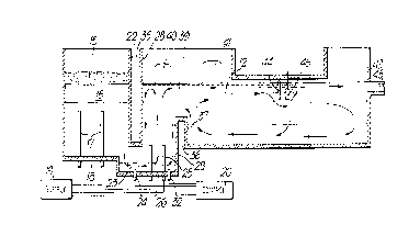
Figure 1 is a plan view of a glass melting tank in accordance
with the present invention,

2Q~40
Figure 2 is a vertical section through the glass melting tank
of Figure 1,
Figure 3 is a view similar to Figure 2 of a different
embodiment of the invention, and
Figure 4 is a view similar to Figure 2 of yet another
embodiment of the invention, and
Figure 5 is a graph showing temperature variation of forward
flowing glass along the length of the tank shown in Figures 1
and 2.
In this example the glass melting tank comprises a melting
chamber 11, a refining chamber 12 and a conditioning chamber
13. A riser chamber 14 is located between the melting chamber
11 and the refining chamber 12. The tank is suitable for use
in producing high quality flat glass such as float glass.
In use solid batch material for producing glass is supplied
through a system such as a hopper system to the top of the
melting chamber 11 so that a blanket of solid batch material
15 lies on top of molten glass 16 in the melting chamber.
Heat is supplied to the melting chamber 16 by an array of
electrodes 17 which are mounted on the base 18 of the melting
chamber and project vertically upwards so as to be immersed in
the molten glass 16. An electrical supply 19 is connected to
the electrode and controlled by a control unit 20. Molten
glass flows out of the melting chamber 11 through a centrally
located exit 21 in the base 18 of the melting chamber adjacent
a downstream wall 22 of the melting chamber. The exit 21
leads to a submerged throat 23 leading centrally into the
lower part of the riser chamber 14. A thermocouple 24 is
mounted in the base of the throat 23 so as to detect the
temperature of molten glass in the throat 23. The

20~74~
-- 7 --
-
thermocouple 24 is connected to the control unit 20.
The riser chamber 14 is provided with an array of electrodes
25 which are mounted on a base 26 of the riser chamber and
project vertically upwards so as to be immersed in the molten
glass in the riser chamber. The electrodes 25 are arranged to
increase the temperature of forward flowing glass so that on
leaving the riser 14 the forward flowing glass is at a
suitable refining temperature higher than the temperature of
the glass entering through the throat 23. The electrodes 25
are located in a central zone of the riser chamber 14 and are
spaced from all four walls (upstream wall 28, downstream wall
29 and opposite side walls 30 and 31 of the riser chamber).
In this way no heat is supplied to the molten glass in the
riser chamber in the region of any of the walls of the
chamber. The electrodes 25 are connected to the power supply
19 and, like the electrodes 17, are arranged to heat the
molten glass by the Joule effect. A thermocouple 32 is
mounted in the base 26 of the riser chamber close to the
downstream wall 29 opposite the throat 23 so as to detect the
temperature of molten glass at the bottom of the riser chamber
in the region close to the downstream wall 29. The
thermocouple 32 is coupled to the control unit 20 so as to
control the power supplied to the electrodes 25 in dependence
on the temperature detected by the thermocouples 24 and 32.
The control 20 provides control of the power supplied to the
electrode 25 in the riser chamber 14 independently of the
control of the power supplied to the electrode 17 in the
melting zone 16. The walls of each chamber in the melting
tank are formed of refractory material so as to withstand the
molten glass in the tank. The arrangement in the riser
chamber 14 is however arranged to minimise corrosion effects
from glass passing through the riser chamber from the melting
tank chamber 16 to the refining chamber 12. The upstream wall
28 of the riser chamber is spaced from wall 22 of the melting

2~ 74~)
- 8 -
chamber so as to provide an air space 35 which acts as a
cooling means for the upstream wall 28 of the riser chamber.
Similarly the downstream wall 29 of the riser chamber is
separated by an air space 36 from the upstream wall 37 of the
refining chamber 12. This air space 36 acts as a cooling
means to cool the downstream wall 29 of the riser chamber.
The two side walls 30 and 31 of the riser chamber are not
facing heated chambers such as the melting and refining
chambers and thereby permit sufficient cooling of the sides of
the riser chamber. By arranging for the air spaces 35 and 36
to cool the upstream and downstream walls of the riser chamber
and by locating the electrodes 25 so that the heat input in
the riser chamber is confined to a central region well spaced
from the side walls of the riser chamber, convective flows are
formed in the glass passing through the riser chamber as shown
in Figure 2. The result is a toroidal flow pattern in which
glass in the central region of the riser chamber is caused to
flow upwardly surrounded by an annular pattern of downwardly
flowing glass adjacent the walls of the riser chamber. In
this way, glass entering the riser chamber through the throat
23 may rise in the central flow together with recirculated
glass which has descended adjacent the walls of the riser
chamber and then ascends in the central upward flow path. The
glass which rises in the central region is then divided so
that some passes over a weir 39 leading into the refining
chamber 12 whereas the remainder is recirculated within the
riser chamber in the toroidal pattern. By use of this system,
the glass which flows forwardly over the weir 39 into the
refining chamber has risen through the riser chamber out of
contact with the refractory walls of the chamber and therefore
has a much reduced likelihood of contamination from corrosion
with the side walls. The glass which flows downwardly against
the side walls is cooled by virtue of the cooling effect of
the air spaces 35 and 36 thereby reducing the likelihood of
corrosion with the side walls and any contamination which does

2 ~ 4 ~
g
_
result may be reduced as the glass rerises in the hotter
central flow as it is recirculated upwardly through the riser
chamber. The thermocouples 24 and 32 are operable to control
the heat input from the electrode 25 so as to ensure that
there is no build-up of cold glass at the bottom of the riser
chamber, particularly starting adjacent the downstream wall
29. Any such build-up of colder glass could gradually
restrict the throat 23 causing the forward flowing glass to
have a higher velocity on entering the riser chamber and
thereby increasing the likelihood of corrosion at the foot of
the wall 28 on entering the riser chamber. To minimise
corrosion in the riser chamber it is important to avoid glass
which enters from the throat 23 rising immediately adjacent
the wall 28. Due to the direction of flow through the glass
melting tank as a whole the likelihood of corrosion in the
riser chamber is greatest on the upstream and downstream walls
28 and 29 but this risk is reduced by the toroidal flow
pattern where the cooler downward flowing glass engages these
walls. The control effected via the thermocouple 32 is used
to ensure that the temperature of molten glass near the base
of the riser 14 adjacent the downstream wall 29 and opposite
the throat 23 is always higher than the temperature of the
glass passing the thermocouple 24 in the throat 23. To
achieve the correct temperature distribution in the riser 14
the electrodes 25 are arranged to input heat in the lower part
of the riser chamber 14. The height of the electrodes 25 is
between 20% and 50%, preferably 30% and 40% of the depth of
molten glass in the riser chamber 14. This provides
sufficient heat input at the lower part of the riser chamber
14 to avoid a build up of cold glass at the bottom of the
chamber 14. In a preferred arrangement, the electrodes 25 are
spaced from the walls of the riser chamber 14 by a distance at
least as great as the height of the electrodes 25. The
lateral spacing between a pair of electrodes 25 may equal the
sum of the width of the throat 23 and the height of the

2 ~
-- 10 --
electrodes 25. The forward spacing between rows of the
electrode 25 may be between 0.8 and 1.4 times the height of
the electrodes 25. The ratio of the volume V of glass in the
riser chamber 14 to the glass load L passing through the tank
is preferably in the range 1.25 to 2.5 m3hr/tonne. The
electrical power required in the risèr chamber 14 is typically
in the range 40 to 60 kw/m3. The power density for the
molybdenum electrodes 25 is typically in the range 20 to 40
kw/dm3 of immersed molybdenum electrodes.
After passing over the weir 39 into the refining chamber the
molten glass is further heated so as to reduce contamination
from impurities and also to release bubbles. The glass may
recirculate as shown by the arrows in the chamber 12 so that
the forward flowing glass is in the upper part of the refining
chamber with a colder return flow at the bottom of the
chamber. Additional heat is applied above the molten glass in
the riser chamber 14 and refining chamber 12 by gas burners
operating through ports such as those marked at 40 and 41.
The glass melting tank is formed with a waist 43 adjacent the
junction between the refining chamber 12 and conditioning
chamber 13.
A barrier in the form of a transverse water-cooled pipe 44
extends across the waist and is submerged in the upper forward
flowing path of the molten glass. The pipe is water-cooled so
as to reduce the temperature of glass entering the thermal
conditoning zone 13 and reduces the rate of flow of hot glass
out of the refining chamber 12 thereby ensuring that the glass
is held for a sufficient time in the refining chamber 12 for
satisfactory refining to occur. The effect of the water pipe
44 does cause some glass to flow downwardly at that point
joining a return flow at the base of the refining chamber 12.
An array of stirrers 45 which may also be water-cooled are

20~7~0
11 --
,
located adjacent the water pipe 44 on the downstream side of
the pipe. The pipe 44 and stirrers 45 may improve the
temperature and homogeneity of the glass entering the
conditioning zone 13. The zone 13 is not normally heated and
the temperature of the glass is gradually reduced on flowing
through the conditioning zone 13 towards an outlet 48 leading
to a glass forming process. The outlet 48 is positioned in
the upper part of a downstream wall 49 of the conditioning
zone so that only forward flowing glass in the upper part of
the conditioning zone 13 leaves through the outlet 48. The
lower levels in the conditioning zone may be recirculated as a
return flow at the lower part of the conditioning zone and
passed back through the refining zone for further refinement
before leaving through the outlet 48.
As explained above, the riser chamber 14 in this example is
used to raise the temperature of forward flowing glass and is
not used for controlled cooling. A graph showing the typical
temperature pattern of forward flowing glass passing through
the melting tank is shown in Figure 5. The temperature Tl of
glass leaving the melting chamber 23 may fall slightly on
passing through the throat 23 and enter the riser chamber 14
at a temperature T2 insufficient for effective refining. The
heat input in the riser chamber 14 exceeds the cooling effect
so that the temperature T3 of glass leaving the riser chamber
14 over the weir 39 is at a suitable refining temperature
higher than T2. On passing through the refining chamber 12
the forward flowing glass cools to temperature T4 but is
always above T2 and sufficient to effect refining. On passing
through the waist 43 the temperature drops to T5 and
controlled cooling to an outlet temperature T6 is effected on
passing through the conditioning chamber 13.
The invention is not limited to the details of the foregoing
example.

2~1874~
- 12 -
In particular, the refining and conditioning zones of the unit
may be designed to operate with various flow regimes in the
molten glass.
Alternatives to the above example are shown in Figure 3 and
Figure 4. Figure 3 shows that the downstream conditioning
zone 50 is much shallower than the refining zone 12. This
creates a situation in which there is only forward flow in the
glass beyond the waist 43. In this manner more efficient use
can be made of the area available for conditioning e.g. to
enable higher glass loading. The deeper refining zone 12
continues to operate with return flows in the glass generated
by the cooling effects of the water-cooled barrier 44 and
stirrers 45 in the waist and of the refiner end wall. The
amount of return flow is reduced compared with the full depth
refining and conditioning and this produces greater thermal
efficiency.
Figure 4 shows that the refining zone 51, waist 43 and
conditioning zone 50 are all of a similar shallow depth to
that illustrated by Figure 3. Under these conditions, there
is only forward flow present in the glass beyond the riser
zone 14. This reduces the energy requirement by virtue of not
having to reheat return flows. The waist section 43 retains a
shallow water pipe 44 to impede the surface flow leaving the
refining zone. The refining zone 51 can be heated either by
above-glass burners 41 or by below glass electric heating or
by a combination of the two methods.
It will further be understood that, if desired, molten glass
could be fed to the riser chamber through a plurality of
throats, for example from a plurality of melting chambers.
Such throats may be through different walls of the riser
chamber which need not be of rectangular form and could have a

2 ~
- 13 -
number of walls other than four. A plurality of riser
chambers 14 may be provided each supplied by a respective
throat. A plurality of risers may be used and may be
connected to a common conditioning chamber.

Dessin représentatif
Une figure unique qui représente un dessin illustrant l'invention.
États administratifs

2024-08-01 : Dans le cadre de la transition vers les Brevets de nouvelle génération (BNG), la base de données sur les brevets canadiens (BDBC) contient désormais un Historique d'événement plus détaillé, qui reproduit le Journal des événements de notre nouvelle solution interne.

Veuillez noter que les événements débutant par « Inactive : » se réfèrent à des événements qui ne sont plus utilisés dans notre nouvelle solution interne.

Pour une meilleure compréhension de l'état de la demande ou brevet qui figure sur cette page, la rubrique Mise en garde , et les descriptions de Brevet , Historique d'événement , Taxes périodiques et Historique des paiements devraient être consultées.

Historique d'événement

Description Date
Inactive : CIB de MCD 2006-03-11
Le délai pour l'annulation est expiré 2000-06-12
Lettre envoyée 1999-06-11
Accordé par délivrance 1999-03-30
Inactive : Taxe finale reçue 1998-12-16
Préoctroi 1998-12-16
Un avis d'acceptation est envoyé 1998-09-08
Lettre envoyée 1998-09-08
Un avis d'acceptation est envoyé 1998-09-08
Inactive : Renseign. sur l'état - Complets dès date d'ent. journ. 1998-09-01
Inactive : Dem. traitée sur TS dès date d'ent. journal 1998-09-01
Inactive : Approuvée aux fins d'acceptation (AFA) 1998-08-14
Toutes les exigences pour l'examen - jugée conforme 1994-02-10
Exigences pour une requête d'examen - jugée conforme 1994-02-10
Demande publiée (accessible au public) 1990-12-13

Historique d'abandonnement

Il n'y a pas d'historique d'abandonnement

Taxes périodiques

Le dernier paiement a été reçu le 1998-06-08

Avis : Si le paiement en totalité n'a pas été reçu au plus tard à la date indiquée, une taxe supplémentaire peut être imposée, soit une des taxes suivantes :

  • taxe de rétablissement ;
  • taxe pour paiement en souffrance ; ou
  • taxe additionnelle pour le renversement d'une péremption réputée.

Les taxes sur les brevets sont ajustées au 1er janvier de chaque année. Les montants ci-dessus sont les montants actuels s'ils sont reçus au plus tard le 31 décembre de l'année en cours.
Veuillez vous référer à la page web des taxes sur les brevets de l'OPIC pour voir tous les montants actuels des taxes.

Historique des taxes

Type de taxes Anniversaire Échéance Date payée
TM (demande, 7e anniv.) - générale 07 1997-06-11 1997-06-09
TM (demande, 8e anniv.) - générale 08 1998-06-11 1998-06-08
Taxe finale - générale 1998-12-16
Titulaires au dossier

Les titulaires actuels et antérieures au dossier sont affichés en ordre alphabétique.

Titulaires actuels au dossier
PILKINGTON PLC
Titulaires antérieures au dossier
PETER JAMES WHITFIELD
ROBERT EMMETT TREVELYAN
Les propriétaires antérieurs qui ne figurent pas dans la liste des « Propriétaires au dossier » apparaîtront dans d'autres documents au dossier.
Documents

Pour visionner les fichiers sélectionnés, entrer le code reCAPTCHA :


Pour visualiser une image, cliquer sur un lien dans la colonne description du document. Pour télécharger l'image (les images), cliquer l'une ou plusieurs cases à cocher dans la première colonne et ensuite cliquer sur le bouton "Télécharger sélection en format PDF (archive Zip)" ou le bouton "Télécharger sélection (en un fichier PDF fusionné)".

Liste des documents de brevet publiés et non publiés sur la BDBC .

Si vous avez des difficultés à accéder au contenu, veuillez communiquer avec le Centre de services à la clientèle au 1-866-997-1936, ou envoyer un courriel au Centre de service à la clientèle de l'OPIC.


Description du
Document 
Date
(aaaa-mm-jj) 
Nombre de pages   Taille de l'image (Ko) 
Description 1998-07-07 13 590
Description 1994-04-17 13 500
Abrégé 1994-04-17 1 14
Revendications 1994-04-17 5 172
Dessins 1994-04-17 4 81
Revendications 1998-07-07 5 207
Dessin représentatif 1999-03-24 1 11
Avis du commissaire - Demande jugée acceptable 1998-09-07 1 166
Avis concernant la taxe de maintien 1999-07-11 1 179
Correspondance 1998-12-15 1 31
Taxes 1996-05-20 1 47
Taxes 1995-05-22 1 51
Taxes 1993-05-20 1 51
Taxes 1992-05-26 1 40
Taxes 1994-05-30 1 46
Correspondance de la poursuite 1994-02-09 1 26
Correspondance de la poursuite 1998-05-25 7 242
Courtoisie - Lettre du bureau 1994-03-07 1 69
Correspondance de la poursuite 1994-08-10 3 53
Demande de l'examinateur 1997-11-26 4 68