Note : Les descriptions sont présentées dans la langue officielle dans laquelle elles ont été soumises.
;f2 ~T .,t ._. ~a y
i ~ ~,,..~ ; C
.. fr
G~ ~ ~ t..~ h_~ a.
-1- RCA 85,479
DYNAMIC VIDEO SYSTEM INCLUDING AUTOMATIC
CONTRAST ~ "WHITE-STRETCH" PROCESSING SECTIONS
The present invention concerns automatic gain
control apparatus for a television system and especially
automatic gain control apparatus affecting the luminance
component in response to certain characteristics of a
reproduced image.
In television systems, it is known to reduce one
or both of the contrast and brightness of a reproduced
image in order to inhibit "white-spot blooming" due to
excessive electron beam currents of the cathode ray tube
(CRT) display device, as well as to inhibit CRT drive and
phosphor amplifier saturation which tend to limit slewrate.
This may be accomplished by directly sensing the beam
current and, in response, generating a control signal for
the contrast and/or brightness control sections of the
system. The control signal may also be generated by
2 0 detecting a characteristic of a video signal coupled to the
cathode ray tube. For example, U.S. Patent 4,599,643,
entitled "Apparatus Responsive To Plural Color Video
Signals For Amplitude Limiting The Video Signals To Assist
Beam Current Limiting", issued to W. E. Harlan, discloses
2 5 combining the three color signals coupled to the cathode
ray tube and detecting the average of the white-going peaks
of resulting signal above a predetermined threshold to
generate a contrast control signal.
While it is desirable to prevent spot blooming,
3 0 for example, by automatically controlling the contrast of
the reproduced image, it is recognized by the present
inventor that such contrast reduction may reduce the
contrast and subjective brightness of the reproduced image.
More specifically, it is recognized that while it is
3 5 desirable to provide automatic contrast control apparatus
to reduce the amplitude of the luminance signal when the
reproduced image includes white-going peaks exceeding a
predetermined level corresponding, e.g., to characters,
-2- RCA 85, 479
mid-range luminance amplitudes will also be reduced. This
results in a contrast and subjective brightness reduction.
To overcome this problem, in accordance with an
aspect of the invention, a non-linear amplitude control
section is coupled in cascade with the contrast control
unit to dynamically emphasize mid-range amplitude luminance
levels relative to high amplitude luminance levels as a
function of the average value of the luminance signal
processed by the contrast control apparatus. For images
1 0 containing excessive white-going peaks but a low level
average luminance component, the effect is to decrease the
amplitude of the white-going peaks while simultaneously
increasing the amplitude of mid-range luminance levels. In
this way, "white spot blooming" (as well as CRT phosphor
and driver saturation) can be minimized while providing
subjectively sharp, bright images.
These and other aspects of the invention will be
described in detail below in connection with the
accompanying Drawing.
2 0 The Drawing includes:
FIGURE 1 showing a schematic, in block form, of a
preferred embodiment of the invention;
FIGURES 1A and 1B showing gain characteristics
useful in understanding the operation of the preferred
2 5 embodiment of the invention;
FIGURE 2 showing a detailed schematic of a portion
of the preferred embodiment shown in block form in FIGURE
1; and
FIGURE 3 showing a detailed schematic of a
3 0 modification to the preferred embodiment shown in FIGURE 1.
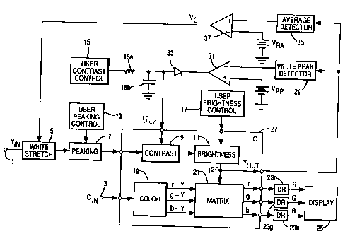
In the television system shown in FIGURE 1,
separated luminance (YIN) and chrominance (CIN) signal
components derived by, e.g., a comb filter (not shown),
from a composite video signal are coupled to respective
3 5 input terminals 1 and 3 and are processed to reproduce an
image.
The input luminance signal component (YIN) is
processed in a cascade of luminance processing sections
t,~ r.. '~~ <_'~' ~;~.
-3- RCA 8 5 , 4 7 9
including a "white-stretch" section 5, a peaking section 7,
a contrast section 9 and a brightness section 11, to
produce a processed luminance output signal YOUT. The
function and operation of "white-stretch" processing
section 5 will be explained in detail below. Peaking,
contrast and brightness sections 7, 9 and 11 are of
conventional design and function as known in the television
field to respectively control the high frequency content of
the output luminance signal (YOUT) corresponding to the
sharpness of image transitions or edges, the amplitude of
POUT corresponding to image contrast, and the DC component
of POUT corresponding to image brightness. Peaking,
contrast and brightness user control units 13, 15 and 17
are provided to allow a user to manually adjust the
1 5 respective characteristics of the image. Each of the user
control units 13, 15 and 17 produces a DC control signal
for the respective luminance processing section, and for
that purpose may include a respective potentiometer.
Alternately, as is more conventional in modern television
2 0 systems, each user control unit may include a respective
digital-to-analog converter which is under the control of a
common control microprocessor. The microprocessor receives
user initiated commands corresponding to the image
characteristics from a keyboard.
2 5 The input chrominance component is processed by a
color processing section 19 including a color demodulator,
a saturation (amplitude) processing unit and a tint or hue
(phase) processing unit (not shown) to produce low level
red, green and blue color difference signals r-Y, g-Y and
3 0 b-Y. Alternately, the color difference signals may be of
the I and Q type. The saturation and tint processing may
be manually and/or automatically controlled by elements not
shown.
The color difference signals, r-Y, b-Y and g-Y,
3 5 and the processed luiminance signal, YOUT, are coupled to a
matrix 21 where they are combined to produce low level red,
green and blue color signals, r, g and b. The low level r,
g and b color signals are amplified by respective drive
ds 4'1 .~ ' :> f
i5 i
fl,~ ~IJ .k_ ?i G: ~.~
-4- RCA 8 5 , 4 7 9
amplifiers (DR) 23r, 23g and 23b to produce high level R, G
and B color signals suitable for driving display device 25.
Display device 25 may be a single direct view cathode ray
tube (CRT), or a projection arrangement comprising
individual red, green and blue CRTs, projection optics and
a screen. In the direct view case, the high level R, G and
B color signals are coupled to respective cathodes of the
common CRT. In the projection case, the high level R, G
and B color signals are coupled to the cathodes of the
respective individual CRTs.
Although not shown for the sake of simplicity, the
television system also includes a synchronization
processing section for deriving horizontal and vertical
synchronization pulses contained in the input luminance
signal YIN. These synchronization pulses are processed to
derive horizontal and vertical retrace blanking pulses
which are inserted, within matrix 21, in the respective
retrace intervals of the low level r, g and b signals so
that display device 25 will be "blanked" during the
2 0 respective retrace intervals in order to avoid producing
visible retrace lines. The synchronization pulses are also
processed by a deflection signal generating unit to produce
deflection signals for the single CRT in the direct view
case, or for the individual CRTs in the projection case.
2 5 Portions of the television system, such as
contrast, brightness, color processing sections 9, 11 and
19 and matrix 21, may be included within a single
integrated circuit IC indicated by block 27. Various
signal input and output terminals are indicated by the
3 0 small circles.
As earlier indicated, it is desirable to limit the
electron beam current in order to avoid "white spot
blooming". Typically, this is accomplished by sensing the
current drawn by the CRT (or CRTs) from the associated high
3 5 voltage power supply and generating a control signal for
reducing one or both of the contrast and brightness of the
reproduced image. In addition to such beam current control
apparatus (not shown), in the television shown in FIGURE 1,
,~ !? ~1, -f :~. n ~.
i%:
a _c. x' ::~' i
-5- RCA 85, 479
the peak drive level is limited to a predetermined value
since electron beam spot size expands non-linearly at
higher beam current amplitudes. Specifically, this is
accomplished by sensing the peak of the processed luminance
signal, YpUT' produced by the cascade of peaking contrast,
and brightness processing sections 7, 9 and 11 to generate
an automatic contrast control signal. The output or
processed luminance signal, YpUT' is utilized, rather than
the input luminance signal, YIN, since Y~UT is influenced
by the peaking, contrast and brightness customer controls.
This type of automatic contrast control (which also may be
called "auto-pix", "pix" being an abbreviation for
"picture"), prevents loss of detail sharpness in high-light
(white) areas due to blooming, while permitting high
contrast (and therefore subjectively bright) images when
the signal peaks stay below the blooming threshold.
With reference to the schematic shown in FIGURE 1,
the automatic contrast control apparatus, in addition to
contrast processing section 9, includes a peak detector 29
2 0 which detects the peaks of the white-going portion of the
output luminance signal, YpUT. A desirable peak detector,
which is capable of responding to very sharp peak signals,
is disclosed in U.S. Patent Application Serial No. 380,697,
entitled "Peak Detector With Feedback", filed on July 14,
2 5 1989 in the name of G.A. Whiteledge. The DC output voltage
of white peak detector 29 is coupled to an amplifier 31
which also receives a reference voltage, VRP, corresponding
to the peak level beyond which blooming is likely to occur.
The output of amplifier 31 is coupled via a diode 33 to the
3 0 junction of a series connected resistor 15a and shunt
connected capacitor 15b comprising a low pass filter
associated with user contrast control unit 15, e.g., to
filter the pulse signal produced by a digital-to-analog
converter. Resistor 15a and capacitor 15b also determine
3 5 the time-constant of the contrast control loop. For the
embodiment shown, it is assumed that white-going portions
of the output luminance signal, YpUT' are positive-going,
that increasing the DC contrast control signal corresponds
. :; s ;?
G~r ~i .~ t ~t: a:
-6- RCA 85, 479
to increasing gain, and therefore increasing contrast, and
that decreasing the contrast control signal corresponds to
decreasing gain and contrast. Accordingly, amplifier 31
is arranged and diode 31 is poled to decrease the contrast
control signal, VC, as a function of the peak of Y~UT'
when Y~UT exceeds the blooming threshold (corresponding to
reference voltage VRP).
The operation of the peak responsive automatic
contrast control apparatus may be better understood by way
of the following quantitative example. It is assumed that
the maximum gain reduction available under automatic
contrast control is 3 dB. In that case, at the maximum
contrast control setting and at the nominal brightness
control setting, maximum gain for the input luminance
signal, YIN, is obtained as long as the peak amplitude of
the output luminance signal, YDUT, is at or below 70 IRE
units. Gain reduction occurs, as needed, as a function of
the peak amplitude of the output luminance signal, for peak
amplitudes between 70 and 100 IRE units. This is shown
2 0 graphically by the gain characteristics associated with
contrast processing section 9 in FIGURE 1A. Curve A
represents the gain characteristic at maximum contrast
control for peak white amplitudes at or below 70 IRE units.
Curve B represents the gain characteristic at maximum user
2 5 contrast control for peak white amplitudes at 100 IRE
units. Curve B also represents the gain characteristics of
any peak white amplitude with contrast control reduced by 3
dB by means of user contrast control unit 15 or by
automatic beam limiting apparatus (not shown).
3 0 As explained above, the white peak responding
automatic contrast control apparatus inhibits spot blooming
when the image contains excessively large white peaks in
small areas corresponding, e.g., to informational
characters or text provided by a television studio or other
3 5 source such as a VCR with an "on-screen" display feature.
However, since the gain characteristics of contrast
processing section 9 is linear, all amplitude levels of the
luminance signal are reduced by the white peak responding
C7 ~ ~ G'~ ~ _ ~ -i,
ert ~ t
,r. , j F,y~ 4.d i ~" c_%
-7- RCA 8 5 , 4 7 9
automatic contrast control apparatus when the image
contains excessive small area white going peaks,
independent of the characteristics of the remaining image.
Thus, e.g., when 100 IRE peak amplitudes corresponding to
characters are suddenly added to a luminance signal
composed exclusively of 70 IRE and lower peaks (i.e., the
normal luminance signal content), mid-range amplitude
levels (e. g., 30-50 IRE) of the luiminance signal as well
as high amplitude levels are reduced. As a result, the
viewer perceives a subjective reduction in the average
brightness of the reproduced image because the 100 IRE peak
amplitude levels associated with small image areas make
only a small difference in the average brightness of the
overall image. "White-stretch" processing section 5 is
directed to this and other concerns.
The gain characteristic for "white-stretch"
processing section 5 is graphically represented in FIGURE
1B. As is indicated in FIGURE 1B, the white-stretch gain
characteristic includes a family of non-linear gain
2 0 functions which have greater gains for mid-range and low
amplitude levels of the input signal than for high
amplitude levels of the input signal. The degree of non-
linearity inversely depends on the magnitude of a control
voltage VC. Thus, the lowest degree of non-linearity
2 5 (i.e., a linear function) is exhibited at the highest
magnitude, VC1, of control voltage VC and the highest
degree of non-linearity is exhibited at the lowest
magnitude, VC2, of control voltage VC. In the preferred
embodiment of the invention, control voltage VC represents
3 0 the average value of the processed luminance signal, YpUT'
The processed luminance signal, YpUT' is utilized rather
than the input luminance signal, YIN, because, in this
manner, the settings of peaking contrast and brightness
processing sections 7, 9 and 11 are taken into
3 5 consideration. Accordingly, when the average value of
processed luminance signal is low (with respect to a
predetermined reference level, VRS), due either to image
content of the received television signal and/or user
-8- RCA 8 5 , 4 7 9
contrast and brightness settings, the mid-range amplitudes
of the processed luminance signal, YpUT' will be boosted or
emphasized relative to the high amplitude level.
Conversely, when the average value is high, the gain
function collapses and becomes linear.
The non-linear white stretch gain control
processing dynamically interacts with the linear automatic
contrast gain control processing. As a result, for
relatively dark images containing small area white
excursions, excessive peak white amplitudes are reduced due
to contrast gain reduction but mid-light amplitudes (which
would otherwise also be further reduced by the linear
contrast gain reduction) are compensatingly increased
according to the non-linear white stretch gain
characteristic.
with reference to the schematic shown in FIGURE l,
the control voltage' VC, for white-stretch processing
section 5 is generated in the following way. An average
detector 35, which may simply comprise an R-C network, is
2 0 utilized to detect the average value of the processed
luminance signal, YpUT. The resulting DC signal is coupled
to one input of an amplifier 37. The other input of
amplifier 37 receives a reference voltage VRA. The control
voltage, VC, for white stretch processing section 5 is
2 5 developed at the output of amplifier 37. Average detector
35 and amplifier 37 are arranged with respect to signal
polarities so that for average values of the processed
luminance signal, YpUT' below VRA, the magnitude of the
control voltage, VC, decreases in direct relationship to
3 0 the average value.
By way of example, white stretch processing
section 5 may be implemented in the manner disclosed in the
concurrently filed Lagoni patent application entitled
"Amplifier Arrangement For Producing A Controllable Non-
3 5 Linear Transfer Characteristic Useful For Improving The
Subjective Contrast Of An Image" referred to above.
Briefly, as is shown in FIGURE 2, the arrangement
disclosed in the concurrently filed application includes
t',, i :. ~~~: ,f~';
' b a..:G s
~tl ~ ~~ Cr
-g- RCA 8 5 , 9 7 9
two PNP emitter-follower amplifiers 201 and 203 having
their inputs coupled in parallel to receive an input signal
and their outputs coupled together by a resistor 205. A
bias voltage VB is coupled to the emitter of emitter-
s follower 203 through a resistor 207 so that emitter-
follower 203 will cut-off before emitter-follower 201.
Below the cut-off voltage, corresponding to bias voltage
VB, emitter-followers 201 and 203 provide the substantially
same output signals. Accordingly, no current flows through
resistor 205. However, above the cut-off voltage, emitter-
follower 203 no longer provides an output signal and
current now flows through resistor 205. By the voltage
division action of resistors 205 and 207, an attenuated
version of the output signal of emitter-follower 201 is
1 5 provided at the junction of resistors 205 and 207 as is
indicated in FIGURE 1B. Accordingly, linear and non-linear
output signals are developed at the respective emitters of
emitter-followers 201 and 203. The two output voltage are
converted into corresponding currents and the
2 0 resulting currents combined by a current steering network
209, comprising a "soft-switch", as a function of control
voltage VC. The overall gain characteristic is as shown in
FIGURE 1B.
White stretch processing section 5 is preferably
2 5 located prior to other gain control sections, such as
contrast processing section 9, as is shown in FIGURE 1,
because, in that way, the amplitude range of its input
signal is relatively constant and predictable. This
simplifies the implementation of white stretch processing
3 0 section 5.
The operation of the television system shown in
FIGURE 1 with respect to the interaction between the
automatic contrast and white stretch provisions is
quantitatively illustrated by the following example. When
3 5 the image has a moderately high brightness value without
white-going portions corresponding to signal components
above 70 IRE, the white peak responding automatic contrast
control apparatus is not active and the white stretch gain
~~a .; ;.
. ' ~~~~.~.~a~r
.-
-10- RCA 85,479
function is linear (VC=VC1 in FIGURE 1B). If signal peaks
of 100 IRE corresponding to small white areas of the image,
e.g., such as characters, are added, the automatic contrast
control apparatus will tend to reduce the amplitude of all
levels of YpUT by up to 3dB. As a result, mid-range
luminance amplitude levels at 50 IRE would tend to be
reduced by about 15 IRE. Reference voltage VRA is
imperically set so that white stretch processing section 5
will apply maximum gain (VC=VC2 in FIGURE 1B) to YIN in
response to the reduction in the average value of YpUT due
to the overall contrast gain reduction under these
conditions. By making the white stretch gain change such
that the 50 IRE amplitude level of YIN increases in the
order of 15 IRE in steady state (i.e., when both white
stretch processing section 5 and contrast processing
section 9 have stabilized), the mid-range gain reduction to
the linear automatic contrast gain control is compensated
for by the non-linear white stretch gain increase.
The quantitative discussion above primarily
2 0 concerns the white stretch gain characteristic for mid-
range amplitudes. With respect to high amplitudes, i.e..,
amplitudes beyond the break-point of the non-linear gain
functions, it has been found, by viewer perception studies,
that the gain (slope) desirably should not be reduced below
2 5 about 0.5.
In addition to the advantageous results obtained
by the dynamic interaction between the white stretch and
automatic contrast control apparatus discussed above, the
white stretch apparatus has been found particularly useful
3 0 in a television system employing relative wideband CRT
drivers to provide greater image resolution. Such wideband
drivers have lower source impedances than lower bandwidth
drivers. The lower source impedances tend to affect the
gamma characteristics of the television system so as to
3 5 reduce mid-range light output. The non-linear white
stretch gain functions, which emphasize or boost mid-range
amplitudes relative to high amplitudes, compensates for the
CA 02021094 1999-11-04
-11-
RCA 85,479
reduction in mid-range amplitudes due to lower source impedance
wideband CRT drivers.
As earlier noted, for automatic contrast and white stretch
control it is desirable ~o detect the peak and average, respectively, of a
s signal representing the luminance component of the reproduced image
after image characteristics, such as contrast and brightness, have been
adjusted so that the respective control signals will properly reflect the
content of the reproduced image. In the embodiment shown in
FIGURE I, the processed luminance signal is available itself for this
io purpose. If the process luminance signal is not available, a signal
representing processed luminance information may be available. For
example, the TA7730 luminance processing IC commercially available
from Toshiba provides at an output terminal a luminance-representative
signal derived by combining r,g,b, color signals which have been
is subjected to contrast and brightness control. Unfortunately, a luminance
or luminance representative signal reflecting contrast and brightness
control processing is not provided by other ICs, e.g., such as the
TDA4580 available from Valvo.
The apparatus disclosed in U.S. Patent 4,980,756 entitled
20 "CONTROL SIGNAL GENERATOR FOR A TELEVISION SYSTEM" is
directed to this problem by combining the r,g,b color signals produced at
respective output terminals of an IC to produce a signal at least
approximately representing processed luminance information. However,
the resulting "summed luminance" signal contains pulses corresponding
25 to the high level (e.g., in the range of -100 to -160 IRE) retrace blanking
pulses contained in the r,g,b signals which are combined, unlike the
summed luminance signal produced by the TA7730 IC, in which r,g,b
signals are combined before retrace blanking pulses are added. The
pulses contained in a summed luminance signal extend significantly
3o below the black level and will therefore substantially affect the average
value (as well as the peak-to-peak value).
m %,
lF' 1. al .L. ', g
-12- RCA 85, 479
Accordingly, a control signal derived by detecting the
average value of the summed signal would not accurately
represent the brightness of the reproduced image. The
control signal generator disclosed in the Lagoni
application also includes provisions directed to this
problem.
A schematic of the circuit disclosed in the
concurrently filed application is shown in FIGURE 3 for the
purpose of disclosing apparatus for practicing the
invention in a television system in which the processed
luminance signal or one representing processed luminance
information is not readily available.
Specifically, with respect to FIGURE 3, the r,g,b
color signals produced at respective output terminals of an
IC are summed by means of a resistive combiner comprising
resistors 301, 303, 305. The resultant summed signal,
produced at the common junction of resistor 301, 303, 305,
is coupled to the base of an emitter-follower amplifier
307. An output signal is developed across a load resistor
2 0 179 at the low impedance emitter output of emitter-follower
307.
A resistor 181 coupled between a supply voltage
source (VCC) and the emitter of emitter follower 307 raises
the conduction threshold of emitter-follower 307 so that
2 5 substantially the entirety of the white-going summed signal
above the black level is provided at the emitter output,
but the pulses, corresponding to the retrace blanking
pulses of the r,g,b, color signals, are removed. Thus, due
to the increased bias applied to the emitter, the detected
3 0 average value and the resultant white-stretch control
signal, VCA, are relatively reliable representations of the
average luminance component of the reproduced image.
While resistors 171, 173 and 175 can be
proportioned according to the well known luminance matrix
3 5 equation to accurately produce a luminance signal, a ratio
of 1:1:1 has been found to be adequate in practice for
providing a processed luminance-representative component
suitable for white-stretch processing control.
- 13 - RCA 85,479
2021094
In addition to the modification discussed above,
other modifications are possible. For example, while
automatic contrast control in the preferred embodiment is
achieved by sensing the processed luminance signal (or a
luminance-representative signal as indicated in FIGURE 3),
it is possible to sense the beam current directly.
Furthermore, while white-stretch processing section 5 is
located prior to contrast processing section 9 in the
1o preferred embodiment for the reasons stated above, it is
possible that a different cascade order could be utilized.
In the same vein, it is possible to combine the functions
of white stretch and contrast processing sections 7 and 9.
In this regard, while the invention has been described in
terms of an analog implementation, it will be appreciated
that a digital implementation may be employed. These and
other modifications are contemplated to be within the
scope of the invention defined by the following claims.