Note : Les descriptions sont présentées dans la langue officielle dans laquelle elles ont été soumises.
2022593
MODULAR BRARES AND CLUTC~S
BACRGROUND OF TH~ INYENTION
._ .
Field of the Invention
-
This invention relates to brakes and clutches having a
special hub structure and permitting easy maintenance.
Discussion of the Prior Art
. . .
United States patent application Serial No. 095,201
discloses a double disc brake or clutch wherein friction pads are
readily removable. Other arrangements for quick change of brake
shoes are shown in U.S. patent ~o. 3,388,775 to Baynes et al. and
in Rlaue patent No. 3,885,650. The desirability of being able to
remove and replace worn friction material easily has been
recognized.
It has also been known that the use of interchangeable
parts in brakes and clutches is desirable, as shown, for example
in U.S. patent 3,964,583 to ~ontalvo.
Summary of the Invention
A single disc, single acting brake or clutch can
incorporate one or more pneu~atically actuated piston and
cylinder assemblies for urging friction material into contact
with a disc rotatable relative to the body which carries the
piston and cylinder assemblies.
2022593
When operated as a brake, a ~tationary body i8 engaged
with a rotating body to stop the motlon thereof. When operated
aq a clutch, upon engagement, the two bodies move together.
The friction coupling mechanism of the present
invention has a novel hub which can be used in either a brake or
a clutch configuration, thus reducing the necessary inventory of
replacement parts. Identical piston and cylinder assemblies,
discs and mounting spiders can also be used in either brakes or
clutches.
The piston and cylinder assembly lor assemblies) is
mounted on a spider. In the case of a brake the spider is fixed
to a machine frame. In the case of a clutch the spider is
mounted on a rotatable shaft. In either case, friction material
carried on the outer face of the piston is moved upon actuation
into engagement with an opposed disc, which is preferably finned
for hea~ dissipation.
The central hub of the assembly is so structured that
in one position it can be used in a brake configuration and in a
reversed position, the hub can function in a clutch. Adapter 33,
bearing 35, adapter fastener 34 are added for the in-drive
function as a clutch.
These simplifications, together with easy removal of
friction material, provide for economical service and replacement
of parts.
One or more piston and cylinder assemblies, which have
disc-shaped cyinder base plates, are mounted by ~eans of screws
on a spider. These piston and cylinder assemblies have hollow
cylindrical torque posts extending from the cylinder base plates
and attached thereto by removable screws. The torque posts hold
generally disc-shaped pads of friction ~aterial in place, so that
the removal of a torque post makes it possible to remove the
friction pad by sliding the pad radially outward.
2022~93
Upon removal of an air fitting through which air under
pre~sure enters the cylinder to actuate the piston, and removal
of mounting screws, the entire piston and cylinder assembly,
including the cylinder base plate, can be removed for service.
The friction material pads face a finned disc against
which they are pushed when air under pressure is fed into the
cylinders to engage the brake or clutch. When air pressure is
relieved the friction pads retract and disengage.
When the central hub of the mechanism is secured to a
rotatable shaft and the spider is attached to a machine frame,
the mechanism operates as a brake. When the hub position is
reversed and the hub is attached to the spider, a spocket adapter
mounts the finned disc to a driven shaft and the mechanism
functions as a ciutch. Upon engagement, the driven shaft rotates
the hub, which in turn rotates the finned disc and the spider
rotates therewith.
Thus the device can function as either a brake or a
clutch, because of its reversible hub.
These and other objects and advantages of the single
disc friction coupling mechanism of the invention will be more
fully understood from the following detailed description of the
invention when that description is read in view of the
accompanying drawing figures.
Brief Description of the Drawings
In the drawings, like reference numerals designate like
parts.
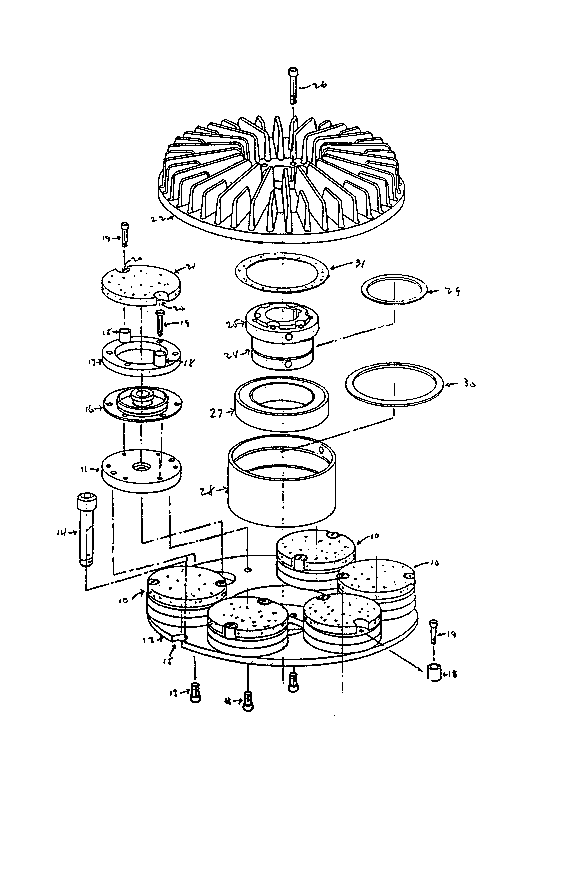
Pig. 1 is an exploded view of a brake according to the
invention.
Fig. 2 is a cross-sectional view of the assembled brake
of Fig. 1.
2022~93
Fig. 3 is an exploded view of the mechanism in a clutch
configuration; and
Fig~ 4 is a cross-sectional view of the assembled
clutch of Fig. 3.
Detailed Description of Preferred Embodiments
Figures 1 and 2 show a brake according to the
invention. Piston and cyinder assemblies 10, of which six are
shown in Fig~ 1, al~hough any number, and in larger sizes a
number greater than six, can be used, are attached through
cylinder base plates 11 to a cylinder mounting plate or spider 12
by mounting screws 13. In the illustrated, preferred
embodiment, two screws 13 secure each piston and cyinder assembly
10 to the spider 12 The cylinder mounting plate or spider 12
i&, in turn, secured to a machine frame (not shown) by reaction
bolts 14 which pass through a slot 15 in the periphery of the
spider 12 in the brake configuration of Figs. 1 and 2.
Each piston and cylinder assembly 10 comprises the
cylinder base plate 11, a piston assembly 16, a ring shaped
piston collar 17, cylindrical torque posts 18 (two per piston
cylinder assembly~ and removable torque post screws 19 which
serve to secure torque posts 18 to the cylinder base plate 11,
which is attached to the spider 12 by mounting screws 13. The
torque posts 18 extend from the piston collar 17 through slots 20
in the periphery of a pad 21 of friction material, which upon
engagement with the friction disc 22 frictionally couples the
disc 22 with the spider 12 and thus to the machine frame,
stopping or controlling the relative rotation of the parts. The
friction disc 22 is preferably finned as shown for dissipation of
the heat generated upon engagement of the brake.
All of the parts described so far, except for the
` 2022~93
reaction bolts 14, are also present ln the clutch configuration
of the mechanism as shown in Figs. 3 and 4. Figs. 2 and 4 also
show the air fittings 23 by means of which air under pressure is
introduced in the cylinders of the piston and cylinder assemblies
10 to move the friction pads 21 outward into enga~ement with the
friction disc 22. It is also possible to actuate the piston and
cylinder a~semblies hydraulically, as will be understood by those
acquainted with brakes and clutches.
The central hub 24 is a generally cylindrical body with
a peripheral flange 25 at one end. In the brake configuration
illustrated in Fig~. 1 and 2, the hub 24 is attached to the
friction disc 22 for movement therewith by means of disc hub
mounting bolts 26. A bearing 27 and a bearing sleeve 28 surround
the central hub 24 and the bearing and bearing sleeve have
retaining rin~s 29 and 30 respectively. A suitable grease gasket
31 is located between the hub 24 and the friction disc 22.
Upon actuation of the piston and cylinder assemblies in
the brake configuration of Figs. 1 and 2, the friction pads 21
engage the friction disc 22 and a shaft (not shown) keyed to tbe
hub 24 is restrained from rotation relative to the machine frame
to which the cylinder mounting plate or spider is attached by
the reaction bolts 14.
When the mechanism is employed as a clutch the hub 24
and the parts associated therewith, i.e. the bearing 27, bearing
sleeve 28, retaining rings 29 and 30 and grease gasket 31 are
inverted from the position shown in Figs. 1 and 2, to that shown
in Figs. 3 and 4, so that the flange 25 of the hub 24 faces the
spider 12 and is secured thereto by means of bolts 32 as best
shown in Fig. 4. In the brake configur?tion of Figs. 1 and 2 the
bolts 32 secure the bearing sleeve 28 to the spider.
Reverting to Figs. 3 and 4 which show the mechanism as
a clutch, it can be seen that a sprocket adapter generally
2022593
designated by reference numeral 33 i8 attached to the disc 22 by
means of fasteners 34 and i8 carried by bearing 35 on the driven
shaft (not shown).
Screws 34 affi~ the sprocket adapter 33 to the disc 22
and bearing sleeve 28. In this clutch configuration, an
additional bearing 35 is provided as shown in Figs. 3 and 4. The
sprocket adapter 33 can thus transmit rotational motion from a
drive shaft to the friction disc 22 at a predetermined speed,
clutching the spider 12 which is mounted on the central hub 24
and carried by a driven shaft (not shown in the drawings).
The fact that the identical hub and other parts can be
used in either a brake or a clutch, by ~imply turning the hub
through 180 and adding the sprocket adapter for use as a clutch,
means that fewer special parts need be manufactured, and spare
parts inventories are greatly reduced. In the case of either
brake or clutch use, the pads of friction material 21 can be
easily replaced by removal of the torque posts and screws 18 and
19 without disassembling the entire device, and entire piston and
cylinder assemblies 10 are also readily removable.
Various modifications, substitutions and variations of
the foregoing preferred embodiments will suggest themselves to
those of skill in the art, and therefore are within the spirit
and scope of the invention.