Sélection de la langue

Search

Sommaire du brevet 2031687 

Énoncé de désistement de responsabilité concernant l'information provenant de tiers

Une partie des informations de ce site Web a été fournie par des sources externes. Le gouvernement du Canada n'assume aucune responsabilité concernant la précision, l'actualité ou la fiabilité des informations fournies par les sources externes. Les utilisateurs qui désirent employer cette information devraient consulter directement la source des informations. Le contenu fourni par les sources externes n'est pas assujetti aux exigences sur les langues officielles, la protection des renseignements personnels et l'accessibilité.

Disponibilité de l'Abrégé et des Revendications

L'apparition de différences dans le texte et l'image des Revendications et de l'Abrégé dépend du moment auquel le document est publié. Les textes des Revendications et de l'Abrégé sont affichés :

  • lorsque la demande peut être examinée par le public;
  • lorsque le brevet est émis (délivrance).
(12) Demande de brevet: (11) CA 2031687
(54) Titre français: SYSTEME POUR REDUIRE LES ERREURS DE DECALAGE DUS AUX POINTS CHAUDS DE LA SOURCE LUMINEUSE DANS UN SPECTROPHOTOMETRE
(54) Titre anglais: SYSTEM TO REDUCE WAVE SHIFT ERROR IN SPECTROPHOTOMETER CAUSED BY HOT SPOTS IN THE LIGHT SOURCE
Statut: Réputée abandonnée et au-delà du délai pour le rétablissement - en attente de la réponse à l’avis de communication rejetée
Données bibliographiques
(51) Classification internationale des brevets (CIB):
  • G01N 21/25 (2006.01)
  • G01J 03/02 (2006.01)
(72) Inventeurs :
  • HONIGS, DAVID E. (Etats-Unis d'Amérique)
(73) Titulaires :
  • NIRSYSTEMS INCORPORATED
(71) Demandeurs :
  • NIRSYSTEMS INCORPORATED (Etats-Unis d'Amérique)
(74) Agent: MACRAE & CO.
(74) Co-agent:
(45) Délivré:
(22) Date de dépôt: 1990-12-06
(41) Mise à la disponibilité du public: 1991-06-07
Requête d'examen: 1997-09-24
Licence disponible: S.O.
Cédé au domaine public: S.O.
(25) Langue des documents déposés: Anglais

Traité de coopération en matière de brevets (PCT): Non

(30) Données de priorité de la demande:
Numéro de la demande Pays / territoire Date
446,595 (Etats-Unis d'Amérique) 1989-12-06

Abrégés

Abrégé anglais


ABSTRACT OF THE DISCLOSURE
An improved near infrared spectrophotometer is
disclosed which reduces wave shift errors arising from
hot spots in a light source. A ground quartz plate
uniformly diffuses radiation from the light source to
evenly illuminate the entrance slit for a diffraction
grating. Radiation emerges from the entrance slit
with a uniform angular intensity distribution and is
dispersed into a spectrum by a reflecting diffraction
grating towards an exit slit. A narrow wavelength
band of radiation passes through the exit slit to
illuminate a sample. Because the entrance slit is
uniformly illuminated, without regard to variations in
radiation intensity due to hot spots in the source,
wave shift errors in the reflectivity measurements for
the sample are reduced.

Revendications

Note : Les revendications sont présentées dans la langue officielle dans laquelle elles ont été soumises.


CLAIMS
1. A spectrophotometric instrument comprising a
housing defining an entrance slit, an optical grating
within said housing positioned to be irradiated with
light transmitted through said entrance slit and to
disperse the received light into a spectrum, a broad
spectrum light source positioned external to said
housing and adapted to direct broad spectrum light
toward said entrance slit, a plate transmissive to
said broad spectrum light positioned between said
light source and said entrance slit, said plate having
a light diffusing interface between said light source
and said entrance slit to diffuse the light
transmitted from said source toward said entrance
slit.
2. A photometric instrument as recited in claim
1, wherein said light diffusing interface comprises a
ground surface on said plate.
3. A spectrophotometric instrument as recited in
claim 2, wherein said light diffusing interface is on
a surface of said plate facing said entrance slit.
4. A spectrophotometric instrument as recited in
claim 1, wherein said light source is an infrared
light source and said broad spectrum light is in the
near infrared wavelength band, and wherein said plate
is a quartz plate.
5. A spectrophotometric instrument as recited in
claim 4, wherein said light diffusing interface is a
ground surface of said plate.

6. A spectrophotometric instrument as recited in
claim 1, wherein said plate is located adjacent to
said entrance slit.
7. A spectrophotometric instrument as recited in
claim 6, wherein said light diffusing interface is on
a surface of said plate facing said interface.
8. A spectrophotometric instrument as recited in
claim 7, wherein said surface is a ground surface of
said plate.
9. A spectrophotometric instrument as recited in
claim 1, wherein said light source comprises a
filament lamp having its filament arranged parallel
with the long dimension of said entrance slit.
10. A spectrophotometric instrument as recited in
claim 9, wherein said light source further comprises
a reflector arranged to focus an image of said
filament near said entrance slit.
11. A spectrophotometric instrument as recited in
claim 10, wherein said plate is located adjacent to
said entrance slit.
12. A spectrophotometric instrument as recited in
claim 11, wherein said light diffusing interface is a
surface of said plate facing said entrance slit.
13. A spectrophotometric instrument as recited in
claim 11, wherein said light diffusing interface is in
the ground surface of said plate.

14. A spectrophotometric instrument as recited in
claim 1, wherein said light diffusing interface is on
a surface of said plate facing said entrance slit.

Description

Note : Les descriptions sont présentées dans la langue officielle dans laquelle elles ont été soumises.

l 2031~87- ~
SYSTEM TO REDUCE WAVE SIII~T ERROR IN SP~C'rROPHOTOMET~R
CAUSED ~Y HOT SPOTS IN THE LIGH~ SOURCE
Background of the Invention
Thls invention relates to a spectrophotometer
using near infrared energy to irradiate samples.
Spectrophotometry determines the concentration of
components in a sample by measuring transmission oE
radiation through or reflection of radiation from a
test samples at narrow wavelengttl bands.
Radiation generated by a light source enters the
spectrophotometer through an~entrance slit. The light
passing through the slit il~luminates an oscillating
diffraction grating which~disperses~the light into~a
spectrum. The spectrum is imaged across an exit slit
and a narrow wavelength~component of the spectrum
passes through the exit~slit and illuminates a sample
after passlng through ~exit slit optics. As the
grating oscillates the~wavelength of the ~spectral
component irradiating the sample is swept~through~the~
0 spect~um.~ ;Accurate~sample; analys~ls~ hlnges~ on t~he
consistency of the angular~position o~ the~spectrum
dispersed ~from tlle gratin`g and errors~in ~spect~ral
measu~rements can ari~se~d~ue~to~inconslst~e~ncleg~ n~the
light source.; For example,~the~light~intensity ac~ross
the entrance slit can vary due ~to hot~spots in the
lamp. The res~ulting~uneven illumination ~of the~slit
causes an apparent shift~in~the position of th~e slit
and~ in the spectrum dispersed~ from the grating.
Consequently, in ~near ~inf~rared~ spectrophotometric
~;~30 analysis, wave shift error of up to ~wo nanometers can
sometimes~;occur ~whén the lamp~ is~ changed, thus
req~uiri~ng reca~libration~o~the~instrument~or~otherwise
reduclng the accuracy~of the snalysis~provided by~the
, ~ ,. -. , . - ~ . , : . . .
,. ~

2û31687
instrument.
The prior art has employed fiber optics to
uniformly illuminate the entrance slit, wit~l some
success. However, the fibers attenuate the radiation
from the light source, reducing the intensity o
radiation llluminating the sample, thus reducing the
signal to noise ratio in the output signal from the
spectrophotometer.
~ : : : , . :
,
: .~ ~ ~ " , , ,......... , .. :-
:~ ' ' ,, .::, ' ,
;: `
',: . :' -'' :
,~:
.
.

203~6~7
SUMMARY OF T~i: INVeNTION
The present invention is a system which lessens
wave shift errors in spectrophotometric readings
without the radiation losses related to fiber optics.
5The invention employs a spectrophotometer with a
ground quartz plate located between a light source,
such as a Eilament lamp, and the entrance slit of the
spectrophotometer. To minimi~e radiation losses in
the space between the source and the slit, the quartz
plate is positioned immediately adjacent to the slit.
Because the ground surface of the quartz plate
diEfuses light from the light source, the entrance
slit is evenly illuminated. Notwithstanding
variations in the incident radiation from the light
source, the light projected from the slit is uniformly
distributed through an angle of projection spanning
the grating so that the grating is uniformly
illuminated. The grating then produces a predictable
spectrum across the exit slit and facilitates accurate
measurement of the sample's reElectivity.
: .
.
:
; ' ;
,,
;' , i.
.
"
.: , . ~ .
. . .
.
,: -
. ~:
:

2~31687
BRIEF DESCRIPTION OF THE DRAWINGS
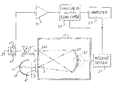
Figure 1 is a schematic drawing of a
spectrophotometer according to the present invention;
and
5Figure 2 is an enlarged fragmented view in
elevation showing the q~artz plate ln front of the
entrance slit of the spectrophotometer and taken along
line 2-2 of Fig. 1.
. .
:. .
' '
: ~ '

2031~87~ ~
DET~ILED D~SCRIPTION OF THE INVENTION
. = ~
As shown ln Figs. 1 and 2, the instrument of the
invention comprises a housing 10 containing a concave
holographic reflection diff~action grating 20,
positioned to be illuminated through an entrance slit
18 by a light source 12 in th~ form of a linear
filament infrared lamp. The lamp 12 geneLates light
with wavelengths distributed through the near infrared
spectrum. A reElector 14 in the shape of an
elliptical cylinder, partially encircles the light
source to reflect light radiated by the light source
12 toward the entrance slit 18. The elliptical
cylindrical shape of the reflector deEines a proximal
focal line along which the linear Eilament of the
light source 10 i5 positioned and a distal focal line
located approximately along the entrance slit 18 so
that an image of the filament is focused near the
entrance slit. Between the light source 12 and the
entrance slit 18 is an infrared light transmitting
plate 21 having a light diffusing interface. The
infrared light transmitting plate comprises a quartz
plate adjacent to the slit 18 with a ground surface
facing the slit~ The ground surface is the light
diffusing interface. Infrared light from the source
12 is transmitted through the plate to the ground
surface where the in~frared light is diffused ta
uniformly illuminate the entrance slit 18.
The slit 18 projècts the light with a uniform
angular~distribution~toward diffraction grating 20,
~hich is~oscilla5ed at high speed by means of a direct
drive motor 22. The details of the direct oscillating
motor drive are~disclosed in copending application
Serial No. ~9~,679,~f~iled January 9, 1989 invented by
Phillip A. McGee, and assigned to the assignee of this
,
;
,
,.
~. . : . .
.
: : ,
- , .
: ., :
~,
,: . :

7 -
application. The grating 20 dlsperses the inErared
light from the sllt la into a spectrum ~e~lected
toward an exit slit 26. A nar~ow wavelength band Erom
the spectrum passes through the exit slit 26 and
through exit slit optics before illumlnating sample
28. As the grating oscillates, the center wavelength
of the light passing through the exit slit is scanned
through the infrared spectrum. Photodetectors 29
detect the lntensity of the resulting radiation
reElected from the sample and generate an output
signal representing this in~ensity. The output signal
of the photodetectors 29 is amplified by an amplifier
31 and applied to an analog-to-digital converter 33.
As the grating oscillates and the center
wavelength of the narrow band passing through the exit
slit is scanned through the spectrum, the analog to
digital converter converts the output analog signal of
the amplifier to digital values at incremental index
points distributed through the spectrum so that a set
of digital values are obtained representing the
intensity of the reflected energy from the sample as
the wavelength irradiating the sample varies
throughout the spectrum~ These~ digital values are
received and processed by a computer 35.
2~ As shown ln Figure l, a shaft position indexing
system 37 coupled to the moto~ 22 transmits pulses to
the analog-to-digital;converter 33 and to the computer
35 as the motor 22 pivo~t~s the~grating 20 and scans the
wavèlength applied to the sample through the spectrum.
In response to each applied pulse, the analog-to-
digital-converter converts the analog signal received
from the amplifier 31 to a digital val~ue and in this
manner ~generates digital values representing the
intensit~ of the reflected r~adiation at increments
~, ~. : : :
,
-
,
:: :
'
.

2~3~687
dlstributed thruugh the spectrum. A computer 35counts the pulses received from the indexing system 37
and thereby monitors the angular position of the
grating 20 and the center wavelength of the band
currently being transmitted through the exit slit.
Thus, the computer 35 monitors the wavelength of
the band which caused the reflected intensity
represented by the digital signal currently applied to
the computer by the analog to digital converter.
Because the entrance slit is uniformly illuminated as
a result of the ground quartz plate, the shaft
position on ~hich the grating is mounted can be
accurately calibrated in terms oi the wavelength being
transmitted through the exit slit. Without the ground
l'; quartz plate to ensure uniform illumination of the
exit slit, variations in the illumination of the
entrance slit caused by hot spots in the light source
would cause an apparent shift in the entrance slit and
cause a corresponding shift in the spectrum reflected
by the grating, so that for a given shaft position of
the grating the wavelength transmitted through the
exit slit might vary by as much as 2 nanometers when
the lamp is replaced. With the ground quartz plate
distributing the light from the light source uniformly
over the entrance slit in accordance with the present
invention, the shift ~ in wavelength caused by
variations in the light source is reduced to 2/100 of
a nanometer. Thusj with the system of the present
~; ~ invention, the system does not need to be recalibrated
when the lamp of the light source is replaced.
The above description is of preferred embodiment
o~ the invention and modification may be made thereto
without departing from the spirit and scope of the
invention, which is defined in the appended claims.
, ~ .
:; :
.. ' ~ '
.
' ' '' ~ '
- . :
` ~ '
- ` '
: ' . . ~ .
. .
' ~ '
~ , ,

Dessin représentatif
Une figure unique qui représente un dessin illustrant l'invention.
États administratifs

2024-08-01 : Dans le cadre de la transition vers les Brevets de nouvelle génération (BNG), la base de données sur les brevets canadiens (BDBC) contient désormais un Historique d'événement plus détaillé, qui reproduit le Journal des événements de notre nouvelle solution interne.

Veuillez noter que les événements débutant par « Inactive : » se réfèrent à des événements qui ne sont plus utilisés dans notre nouvelle solution interne.

Pour une meilleure compréhension de l'état de la demande ou brevet qui figure sur cette page, la rubrique Mise en garde , et les descriptions de Brevet , Historique d'événement , Taxes périodiques et Historique des paiements devraient être consultées.

Historique d'événement

Description Date
Inactive : CIB de MCD 2006-03-11
Demande non rétablie avant l'échéance 2000-12-06
Le délai pour l'annulation est expiré 2000-12-06
Réputée abandonnée - omission de répondre à un avis sur les taxes pour le maintien en état 1999-12-06
Modification reçue - modification volontaire 1997-12-17
Lettre envoyée 1997-10-24
Inactive : Renseign. sur l'état - Complets dès date d'ent. journ. 1997-10-20
Inactive : Dem. traitée sur TS dès date d'ent. journal 1997-10-20
Exigences pour une requête d'examen - jugée conforme 1997-09-24
Toutes les exigences pour l'examen - jugée conforme 1997-09-24
Demande publiée (accessible au public) 1991-06-07

Historique d'abandonnement

Date d'abandonnement Raison Date de rétablissement
1999-12-06

Taxes périodiques

Le dernier paiement a été reçu le 1998-10-06

Avis : Si le paiement en totalité n'a pas été reçu au plus tard à la date indiquée, une taxe supplémentaire peut être imposée, soit une des taxes suivantes :

  • taxe de rétablissement ;
  • taxe pour paiement en souffrance ; ou
  • taxe additionnelle pour le renversement d'une péremption réputée.

Les taxes sur les brevets sont ajustées au 1er janvier de chaque année. Les montants ci-dessus sont les montants actuels s'ils sont reçus au plus tard le 31 décembre de l'année en cours.
Veuillez vous référer à la page web des taxes sur les brevets de l'OPIC pour voir tous les montants actuels des taxes.

Historique des taxes

Type de taxes Anniversaire Échéance Date payée
Requête d'examen - générale 1997-09-24
TM (demande, 7e anniv.) - générale 07 1997-12-08 1997-12-03
TM (demande, 8e anniv.) - générale 08 1998-12-07 1998-10-06
Titulaires au dossier

Les titulaires actuels et antérieures au dossier sont affichés en ordre alphabétique.

Titulaires actuels au dossier
NIRSYSTEMS INCORPORATED
Titulaires antérieures au dossier
DAVID E. HONIGS
Les propriétaires antérieurs qui ne figurent pas dans la liste des « Propriétaires au dossier » apparaîtront dans d'autres documents au dossier.
Documents

Pour visionner les fichiers sélectionnés, entrer le code reCAPTCHA :


Pour visualiser une image, cliquer sur un lien dans la colonne description du document. Pour télécharger l'image (les images), cliquer l'une ou plusieurs cases à cocher dans la première colonne et ensuite cliquer sur le bouton "Télécharger sélection en format PDF (archive Zip)" ou le bouton "Télécharger sélection (en un fichier PDF fusionné)".

Liste des documents de brevet publiés et non publiés sur la BDBC .

Si vous avez des difficultés à accéder au contenu, veuillez communiquer avec le Centre de services à la clientèle au 1-866-997-1936, ou envoyer un courriel au Centre de service à la clientèle de l'OPIC.


Description du
Document 
Date
(aaaa-mm-jj) 
Nombre de pages   Taille de l'image (Ko) 
Abrégé 1994-03-31 1 22
Revendications 1994-03-31 3 127
Dessins 1994-03-31 1 50
Description 1994-03-31 7 264
Dessin représentatif 1999-07-18 1 15
Rappel - requête d'examen 1997-08-05 1 117
Accusé de réception de la requête d'examen 1997-10-23 1 178
Courtoisie - Lettre d'abandon (taxe de maintien en état) 2000-01-03 1 185
Taxes 1996-09-19 1 52
Taxes 1994-10-24 1 45