Note : Les descriptions sont présentées dans la langue officielle dans laquelle elles ont été soumises.
2033794
B~C~GRO~rND OF THE IN~JENTION
FIEI.D OF INVENTION
This invention relates to a device for providing
audible messages and, more particularly, to a self-con~ained
device for siving such audible messages to occupants of a
vehicle .
iO
DESCRIPTION OF PRIOR ~RT
Use of a seat belt in an automobile for preventing
serious injury and death is known, and considerable efforts
have been focused on encouraging non-wearers to wear seat
belts. These efforts include promotional campaigns, vehicle-
installed warning buzzers and lights, passive restraint
systems, and even legal fines. Unfortunately, many lives are
still lost every year which could otherwise be saved by
buckled seat belts.
Many people simply forget to wear their seat ~elts.
Veh~cle-~nsta~led wz-ning lights and buzzers were intended as
reminders to otherwise forgetful passengers. These indicators
were viewed by many motorists as annoyances and were, in many
cases, disconnected, thereby defeating their purpose.
.
Known synthesized voice systems are available and
are largely well-received by most people. Telephone numbers
are being given by synthesized voices, soda machines are
suggesting different selections, and now virtually all car
manufacturers offer automobiles with a synthesized voice to
warn the motorist of various conditions, such as keys left in
the ignition, low oil, etc. The synthesized voice is being
used to remind motorists to secure their seat belts and this
approach resulting in a greater number of motorists securing
their seat belts.
- _ 2 2033794
While the use of synthesized voice seat belt warning
systems has been proven successful and necessary, a problem
exists with the millions of older vehicles with systems which
are inadequate, disconnected or nonexistent.
Another consideration is that a driver may want to
warn his passengers to buckle their seat belts during their
journey; available systems are incapable of re-announcing the
warning to delinquent passengers.
Accordingly, there exists a need for providing in
vehicles, seat ~elt systems which may be operated at will.
Numerous innovations are known for self-contained
devices providing audible messages to vehicle occupants.
Although these innovations have use for specific purposes,
they are not suitable for the purposes of the present
invention as heretofore described.
S~MMARY OF T~E lNV~NlION
One feature of the present invention is to provide a
self-contained device for giving audible messages to occupants
of a vehicle, avoiding disadvantages of the prior art.
More particularly, it is an object of the present
invention to provide a reminder device. Power is supplied to
the reminder device when the ignition switch is turned on.
The reminder device of the present invention
includes a housing and circuit means contained within the
housing, the latter having a speech synthesizer for generating
an audible message. The device further includes means to
electrically interconnect the circuit means and an electrical
outlet. Thus, the speech synthesizer is activated to generate
the audible messages when the ignition switch is turned on.
The reminder device still further includes a normally open
2033794
s~itch that is electrically connected to the circuit means.
The momentary closure of the nor~ally open switch deactivates
the speech synthesi~er to halt the audible message, once the
speech s~nt~esizer has been activated by turning on the
ignition switch. Thus, the reminder device is entirely self-
contained and adapted to be ins~alled in the vehicle.
The use of such a device reminds the driver to
respond to a recorded message which may indicate the safety
lo benefits, or the legal responsibility of such. A remote
switch of the system may be pressed to deactivate the message.
This switch, which may alternatively activate the message, may
be pressed when passengers do not secure their seat belts.
Thus, the system circumvents known systems since it allows the
driver to remind other passengers.
A preferred form of the device is a self-contained
device for giving audible messages comprising, a housing
having a top, a side, and a front, a power source disposed
remotely from the housing, a VELCROR strap disposed on the top
of the housing so that the self-contained dev-ce giving
audible messages can be .mcun~ed under the d2shboard or the
vehicle, a first ne~ative elect~ode disposed from the housing,
a first positive electrode disposed from the housing, the
first positive electrode and the first negative electrode
together connecting the self-contained device for giving
audible messages to the remote power source, a normally open
switch disposed remotely from the housing, a light emitting
diode, a second negative electrode disposed from the housing,
and a second positive electrode disposed from the housing, the
second positive electrode and the second negative electrode
together connecting the normally open switch to the lisht
emitting diode.
Another em~odiment of the present invention includes
a speaker disposed in the side of the housing.
2033794
Another feat~lre is the presence of a variable
resistor switch disposed on the f-ont of the housing so that
the intervals for starting the messages 2re also manually
controllable.
s
In yet another feature of the present invention
there is provided a volume control switch disposed on the
front of the housing enabling control the message volume.
Still another feature of the present invention is to
provide a power source operable by the vehicle cigarette
lighter.
Having thus generally described the invention,
reference will now be made to the accompanying drawings,
illustrating preferred embodiments.
BRIEF DESCRIPTION OF THE DRA~INGS
In the drawings, wherein similar reference numerals
denote similar features throughout the several views:
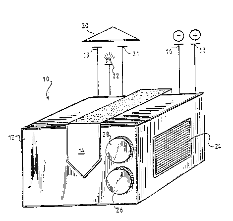
Figure 1 is a perspective view or the self-contained
device of the present invention mounted underneath the
dashboard of the vehicle;
Figure 2 is an oblique view of Figure l; and
Figure 3 is a schematic diagram of the interval
circuitry means for controlling the intervals of time in which
the audible message of the invention is to be repeated.
DETAI~ED DESCRIPTION OF T~E PREFERRED EMBODI~ENTS
Referring to the drawings in which like numerals
indicate like parts, the overall structure is designated by
12 which is a housing containing a speaker 24 and circuitry
2033~94
for producing a voice message. A VELCROR support strap 14
secures housing 12 to the underside of a vehicle dashboard
(not shown).
The device 10 receives ~ower f~om the vehicle
through negative lead 16 and positive lead 18 which may
terminate at their ends at a vehicle cigarette lighter adaptor
(not shown). Alternatively, negative lead 16 and positive
lead 18 may be connected to the power line of an accessory
(not shown). The normally open switch 20 is remotely
connected to the device 10 and provides manual activation or
deactivation of the message.
The device 10 is easily retrofitted into a vehicle
lac~ing such a warning device. The negative lead 19 may be
attached to any appropriate structure under the dashboard as
long as it is spaced apart from the housing 12, a sufficient
distance, to assure that the speaker 24 will be free from
obstructions. The VELCROR support strap 14, of suitable
length, secures the device 10 to the vehicle. The negative
lead 16 and the positive lead 18 are attac~.ed to respective
positive and negative connections within the vehicle. With a
proper adaptor, the device 10 may be plugged into a vehicle
cigarette lighter socket or connected to the power wiring of
an accessory, i.e. radio, heater, signal lights, etc. Device
10 is thus activated when an ignition or accessory switch is
in the "ON" position, and is deactivated when such switch is
in the "OFF" position, using a common ground.
Normally open switch 20 may take various forms, but
will still be easily operable by the driver. Switch 20 is
disposed at a convenient, remote location and is electrically
connected to device 10. This enables a driver to attach the
device 10 in th2 center of the bottom of the dashboard where a
floor hump (only on rear wheel and four wheel drive vehicles)
obscures free space from the dashboard center so that the
normally open switch 20 must be mounted to the lower-left-hand
- 2033794
portion of the dashboard for convenient reach. The switch 20
is an illuminated normally open momentary switch, which is
approximately the size of a quarter, and may be adhered to any
convenient location.
S
The device 10 is suspended by the strap 14 from e.g.
a krac~et or wire harness under the dashboard. The device 10
is suspended high enough thus allowing the occupants of the
vehicle exposure to the speaker 24.
In normal operation, power is supplied to the device
10 through the negative lead 16 and the positive lead 18 when
the ignition is switched on, as, for example, when the vehicle
is started. The negative lead 16 and the positive lead 18 are
twenty-gauge wire and are approximately four feet long to
provide sufficient length to mount the normally open switch.
A synthesized voice will begin to warn the driver by repeating
a message, which continues to be repeated until the normally
open switch 20 is pressed.
The driver of the vehicle may press the normally
open switch 20 before the message is fully announced. The
circuitry provides for complete subsequent messages. In this
normal mode, the single pressing of the nor~ally open switch
20 will deactivate the device 10.
The device supersedes known systems currently
installed in vehicles today by giving the driver the ability
to activate the device 10 whether or not the ignition has been
switched off and back on. If, for example, a passenger enters
the vehicle while the engine is running, the driver may
manually activate the device lO by pressing the normally open
switch 20 once, to start the message. The normally open
switch 20 acts as a toggle to alternately turn the device 10
on and off, so that once the new passenger has received the
message, the normally open switch 20 can be pressed a second
time to stop the message.
203379~
The individual circuits of the device 10 include a
voltage regulator 30 which converts the vehicle voltage to the
required .~orking voltage and further protects the device 10
from surges in powe . A speech proces~or is provided for
creating the message and may take the form o-^ a Dreprogrammed
ROM, while a low pass rilter sends the signal to the audio
amplifier for driving the speaker 24.
The normally open switch 20 is connected to the
speech processor and provides manual activation or
deactivation of the message. A light emitting diode (L.E.D.)
22 may be installed between the power source and the circuitry
for protection against reverse voltage spikes which are known
to occur in vehicle electrical systems.
Additionally, the device 10 is provided with a
volume control 28 and a variable resistor switch 26. The
volume control 28 regulates the audible message volume. The
variable resistor switch 26 regulates the intervals for
starting the message.
Figure 3 is a schematic diagram illustrating the
circuitry of the interval circuitry timing means for
controlling the time inte~al over which the audible message
is to be repeated to passengers of the vehicle. In addition
to the other features heretofore discussed, the interval
circuitry means includes a timer device 32 and synthesizer 34.
It will be understood that each of the elements
described below, or two or more together, may also find a
useful application in other types of constructions differing
from the type described above.
While the invention has been illustrated and
described as embodied in a self-contained device for giving
audible messages to occupants of a vehicle, it is not intended
to be limited to the details shown, since it will be
_ 8 Z033794
understood that various omissions, modifications,
substitutions and changes in the forms and details of the
device illustrated and in its operation can be made by those
skilled in the art without departing in any way from the
spirit and scope of the present invention.