Note : Les descriptions sont présentées dans la langue officielle dans laquelle elles ont été soumises.
~3~
Description
Composite Structures Molding
Technical Field
The present invention relates to a method and
apparatus for molding hollow composite articles having
a plurality of internal webs.
Background Art
Composite aerospace structures such as tailfins,
wings, canards, and other control surfaces are usually
hollow and generally have internal spar wabs for
structural reinforcement. The location and alignment
of these spar webs determines the strength and
sti~fness of ~he fabricated part as well as its
ability to mate with adjoining assemblies. To
eliminate problems of adhesion between structural
elements and improve the strength of the ~inished
part, it i5 highly desirable to cure spar webs
integrally with the shell of the part to be molded.
Composite structures with integral spar wehs
were previously molded using uncontrollable inflatable
nylon bags and fixed-size hard mandrels. These nylon
bags provided good pressure during curiny of the
laminate but were prone to tearing. When this
sccurred, the part and mold had to be removed from the
autoclave, vacuum rechecked and/or rebagged, and
r~inserted into the autoclave for cure. This was a
time consuming pxocess which sometimes approached the
maximum handling time of the pre-preg material.
Exceeding this maximum handling time meant that the
pre-preg might not bond and cure properly, and that
the part would have to be discarded.
S-4~69
.
, ,, , ~ : .
2~3~
The fixed-size mandrels were typically located
centrally within each of the internal cavities of the
mold. The mandrels were sized approximately 0.250
inch per side smaller than the internal dimensions of
the final part size to allow for the lay-up of khe
part's laminates.
Because of their undersize condition, fixed-
size mandrels were deficient in controlling the
positions of the critical spar webs and spar
extensions. Spar extensions are continuations o~ the
internal spars which project beyond the skin of the
part and are used to fasten the part to the fuselage.
As a result of the mandrels (100) being smaller
than the part size, the spar webs were able to move in
the space between adjacent mandrels during the forming
process (See Figure 1). Cured spar webs exhibited an
unacceptable amount of waviness (101) and were not
accurately positioned at their ideal locations. The
waviness caused a reduction in the physical properties
of the cured composite structure and the mislocation
of spar extensions (102) caused interface problems in
the next assembly operation of the part. If the
mislocation tolerance was exceeded, considerable
rework was required, and possibly a costly major
assembly could be scrapped.
Patent No. 3,962,506 describes a flexible and
inflatable mandrel for producing hollow products
having non-circular cross-sections. Although commonly
used in composites molding, uncontrolled inflatable
apparatus do not provide for the accurate alignment
and contrQl of the spar webs required in our
application.
Disclosure of Invention
. ~ : , . ..
~3~flt~ ~
The invention relates to a method and apparatus
for molding hollow composite articles having a
plurality of internal webs.
The method according to the invention may be
most advantageously used to improve th~ ~uality and
accuracy of composite aircra~t structures such as
wings, fins, and other hollow control sur~aces having
integrally cured spar webs. These spar webs function
as reinforcements within the structure and contribute
to the strength and stiffness of the finished part.
The new molding and curing method disclosed is
designed to eliminate the problems associated with the
use of uncontrollable inflatable bags and fixed-sized
hard mandrels in molding aircraft parts. In order to
eliminate the waviness in spar webs and the
mislocation o~ spar extensions, while providing a
homogeneous laminate quality, a mold assembly was
designed to include expandable mandrels, means to
accurately locate the spars, and inflatable pressure
membranes to uniformly compress the laminates.
The expandable mandrels, in a compressed
position during the lay-up process, provide adequate
room for lay-up with non-debulked materials.
Expanding the mandrels before the curing cycle pre-
positions the spars, assures spar straightness, and
avoids the waviness problems associated with fixed
size mandrels. The mandrels may be expanded by a
variety of means, such as pneumatic cylindQrs, wedge
and roller assemblies, or hydraulics.
The precise location of integral spar webs is
achieved by ~ plurality of hard stops on each end of
the mvld. These stops limit the expansion of the
mandrels. Since the sequence of activation of the
expandable mandrels is critical in order to precisely
set the spar web locations in the part, a manifold is
.
,
- ~ :
, .
preferably incorporated to ensure that only the proper
sequence of operations of the mandrels is possible.
An inflatable pressure membrane is inaorporated
to form the interior surfaces of khe part. Thi~
allows the drawing o~ a vacuum between the inner mold
surface and the membrane, capturing the part
therebetween. A membrane with a high degree of
elasticity is preferred, so that it will form tightly
onto the mandrels during the lay-up process but expand
freely when vacuum and heat are applied to tightly
compress the laminate material during the cure cycle.
The flexible pressure membranes apply uniform pressure
to tha laminate pre-preg, thereby avoiding resin rich
and resin poor areas in the finished part.
The foregoing and other features and advantages
of the present invention will become more apparent
from the following description and accompanying
drawings.
Brief Description of Drawings
Figure 1 illustrates the spar web waviness
problem and spar extension offset associated with
fixed-size mandrels.
Figure 2 illustrates the expandable mandrel
design.
Figure 3 illustrates adjacent mandrels in a mold
in their contracted position.
Figure 4 illustrates the mold assembly.
Figure 5 is a cut-away side view illustrating
the location of the press-tight adhesive and vacuum
valve which allow a vacuum to be drawn on the mold
cavity.
Figure 6 illustra~es adjacent mandrels in a mold
in their expanded position and the pressure membranes
fully inflate~.
- 4 -
: ~
~ ~ 3 .~
Best Mode for Carrying Out the Invention
Referring now to the drawings, it is the molding
of hollow composite articles having a plurality of
internal webs with which this invention i5 aoncerned.
In particular, the invention is used to manufacture
aircraft tailfins.
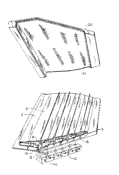
Figure 2 illustrates an expandable mandrel
apparatus. The mandrels may be construc~ed o~
alu,minum and consist of a set of slidable sidewall
members. There is an interior sidewall member (2j and
an exterior sidewall member (3). The interior
sidewall member (2~ can slide within the exterior side
wall member (3) to adjust the width of the mandrel
(1). At the ends of the interior sidewall member (2)
are located a vertical support braces(4) which are
attached to mandrel support posts (5).
Within each mandrel is a set of four pneumatic
cylinders (63, transversely mounted between the two
' slidable wall members. The cylinders (6~ have two
chambers. A differential pressure can be created
within these chambers that will cause one chamber to
expand, extending an attached cylinder rod (7), and
causing the sidewall plates connected thereto to move
apart.
Surrounding the length of the expandable mandrel
is an in~latable pressure membrane (8). In this
prefPrred embodiment the membrane (8) is composed of
silicone rubber~ The silicone material allows the
drawing of a vacuum between the inner mold surfaces
and the silicone membrane, capturing the part within.
The silicone membranes form well to the 0.125 inch
typical inner radii of the part without the tearing
pro~lem associated with nylon membranes. The silicone
membranes actually extend heyond the lay-up areas and
beyond the ends of the mandrels to facilitate the
;. :
, :~ : , ;
~ ~ D~
sealing of the mold cavity into an air tight
enclosure.
The pre-prey materials used to form the spars
webs (13, 17) are laid up on what may be called rain
5 gutter ~orms to construct a "C" shaped articl~. In
this application, the material is 5225W epoxy resin
and a graphite epoxy pre-preg produced by Narmco, Inc,
(Anaheim, CA). The pre-formed pre-pregs (13, 17) are
placed onto the silicone membrane covered mandrels.
Adjacent to each end of the lower mold section
is a bracket support plate ~4). On this bracket
support plate (14) are mounted mandrel alignment
brackets (15). These alignment brackets (15) support
the mandrels (1) in the lower mold sPction (9) and
align the mandrels lengthwise in the mold cavity.
The lower mold section (9) is line~ with woven
pre-preg material (22) which forms the skin of the
fin. The prepared mandrels are then placed in said
mold adjacent to each other in a spaced apart
arrangement and supported at each end by said
alignment brackets (15). (See Figure 3).
Located at the ends of the lower mold section
(g) are a plurality of spar locators (16) which act as
hard stops to the mandrels expansion. These locators
~16) set the precise chordwise location of the spars
when the mandrels are expanded. Locators (16~ are
generally the same thickness as the two ad;oining pre-
form pre-preg layers (13, 173. When the mandrels
expand, the pre-preg layers (13, 17) are brought into
contact with each other, but are not compressed.
Referring now to Figure 4, located on an
extension of the lower mold section (9) is a manifold
(10), bearing quick connect couplings (11), attached
to which are air lines (12) and vacuum lines (19)
which are connected to the pneumatic cylinders (6) to
supply pressurized air and vacuum during the molding
-- 6 --
.. . .
2~ ~3
process. The pneumatic cylinders ~6) within
individual mandrels are connected in series to ensure
even expansion of the mandrel along its length.
The upper mold section (20), previously lined
with woven pre-preg (21) to ~orm the outer skin o~ ~he
fin, is placed over the lower mold section containing
the mandrels and the two sections are bolted together.
Air lines (12) connected to the pneumatic cylinders
(6) are attached to the manifold.
As previously described, the inflatable pressure
membranes (8) surround the expandable mandrels like
tubes and extend beyond the length of the mandrels and
the mold. (See Figure 5~. This allows the edges of
these membranes to be sealed to adjacent pressure
lS membranes on either side and to the upper and lower
mold sections. The cavity between the membrane (~)
and the mold is sealed by means of a tacky
nonhardening press-tight adhesive (25) such as GS-213
sealant tape by Air Tech International, Inc. (Carson,
CA) in conjunction with a nylon bagging film (28). A
bead of adhesive (25) is applied to the outer edge of
the memhrane (8) and to the end of the exterior
surface of the mold sections. Nylon bagging film (2~)
is wrapped around the ends of the mold and secured
with the adhesive (25). This completely seals the mold
cavity containing the pre-preg materials and allows a
vacuum to be drawn on the cavity during the molding
process. At either end of the mold a large ear fold
(30) is foxmed by the bagging film (28) to provide
sites for mounting vacuum valves S26). Within the ear
fold (30) is a woven cloth gauze (29) to provide an
open channel for air withdrawal. The vacuum valve
(26) is connected to a vacuum hose (27) during the
molding process to effect evacuation of th mold
cavity during the cure cycle.
.
~3~
Prior to the cure cycle, the manifold (10) is
attached to an exterior supply of compressed air and
the mandrals (1) expanded until they contact the spar
locators (16) to precisely set the location Q~ the
spars webs.
The entire mold assembly, and manifold are
placed in an autoclave. The mold assembly and
enclosed pre-preg is subjectad to suf~icient heat and
pressure to bond adjacent pre-preg materials and
convert them to void free composites. In this
application the autoclave pressure is about 50 psi,
and the temperature is about 350F.
During the cure process, a vacuum is drawn on
one chamber of the pneumatic cylinders (6), while the
other chamber is exposed to autoclave pressure via the
manifold. This causes the mandrels to remain at their
fully expanded position, taking up the 0.250 inch gap
normally seen with fixed-size mandrels.
While the mold cavity is evacuated, autoclave
pressure pressing on the inside of the inflatable
pressure membranes(8) causes them to expand like a
balloon, compressing the adjacent pre-preg pre-forms
(13, 17) together to form composite spars. The
expandable membrane also compresses the edges of the
spars against the pre-preg lined mold cavities to
integrally bond the spars webs to the skin. (See
Figure 6) Typically the composite pre-preg is held at
the designated temperature and pressure for 3 hours.
Although this invention has been shown and
described with respect to detailed embodiments
thereof, it will be understood by those skilled in the
art that various changes in form and detail thereof
may be made without departing from the spirit and
scope of the claimed invention.
.
:. : :
. . . : :.