Sélection de la langue

Search

Sommaire du brevet 2035902 

Énoncé de désistement de responsabilité concernant l'information provenant de tiers

Une partie des informations de ce site Web a été fournie par des sources externes. Le gouvernement du Canada n'assume aucune responsabilité concernant la précision, l'actualité ou la fiabilité des informations fournies par les sources externes. Les utilisateurs qui désirent employer cette information devraient consulter directement la source des informations. Le contenu fourni par les sources externes n'est pas assujetti aux exigences sur les langues officielles, la protection des renseignements personnels et l'accessibilité.

Disponibilité de l'Abrégé et des Revendications

L'apparition de différences dans le texte et l'image des Revendications et de l'Abrégé dépend du moment auquel le document est publié. Les textes des Revendications et de l'Abrégé sont affichés :

  • lorsque la demande peut être examinée par le public;
  • lorsque le brevet est émis (délivrance).
(12) Brevet: (11) CA 2035902
(54) Titre français: CONTENANT EN RESINE SYNTHETIQUE, EN FORME DE BOUTEILLE
(54) Titre anglais: SYNTHETIC RESIN BOTTLE-SHAPED CONTAINER
Statut: Périmé et au-delà du délai pour l’annulation
Données bibliographiques
(51) Classification internationale des brevets (CIB):
  • B65D 01/02 (2006.01)
  • B65D 23/00 (2006.01)
(72) Inventeurs :
  • OTA, AKIHO (Japon)
(73) Titulaires :
  • YOSHINO KOGYOSHO CO., LTD.
(71) Demandeurs :
  • YOSHINO KOGYOSHO CO., LTD. (Japon)
(74) Agent: MARKS & CLERK
(74) Co-agent:
(45) Délivré: 1999-01-12
(86) Date de dépôt PCT: 1990-07-06
(87) Mise à la disponibilité du public: 1991-01-08
Requête d'examen: 1995-06-28
Licence disponible: S.O.
Cédé au domaine public: S.O.
(25) Langue des documents déposés: Anglais

Traité de coopération en matière de brevets (PCT): Oui
(86) Numéro de la demande PCT: PCT/JP1990/000867
(87) Numéro de publication internationale PCT: JP1990000867
(85) Entrée nationale: 1991-03-06

(30) Données de priorité de la demande:
Numéro de la demande Pays / territoire Date
1-80237 (Japon) 1989-07-07

Abrégés

Abrégé français

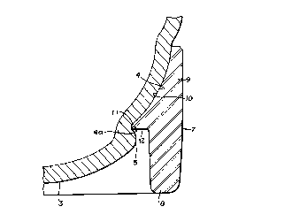
Une bouteille en résine synthétique comprend un corps et une base qui la maintient debout de manière stable. Le corps (1) de la bouteille est fabriqué en résine synthétique par formage biaxial, avec étirage-soufflage, avec un fond courbé vers l'intérieur dans sa partie centrale (6) et une large rainure d'enclenchement (4) formée autour de sa périphérie extérieure. La base (7) est un court cylindre dont le diamètre extérieur est presque identique au diamètre du tronc (2) du corps (1). Sa moitié supérieure forme un cylindre (9) d'enclenchement avec la rainure (4) du corps de la bouteille, alors que sa moitié inférieure forme un pied cylindrique (8) situé sous l'extrémité inférieure du fond (3) du corps de la bouteille lorsque la base enclenche le corps. Cette base peut être aisément assemblée de manière précise avec le corps de la bouteille et augmente la résistance aux impacts du fond de la bouteille.


Abrégé anglais


This invention relates to a synthetic resin
bottle-shaped container comprising a bottle-shaped main body and a
pedestal body for providing stable self-standing capability
to the main body. The bottle-shaped main body is made of a
biaxially-oriented blow-molded synthetic resin material. A
center portion of a bottom portion of the main body is
depressed inwardly and a curved outer peripheral surface area
of the bottom portion is formed to a wide press-fit recess to
be engaged with a pedestal body. The pedestal body is a
short cylindrical portion with an outer diameter
substantially equal to that of the bottle portion of the main
body, and comprises an upper half portion for engaging with
the press-fit recess of the bottom portion, and a lower half
portion for accommodating the bottom portion, so that the
lowest end of the pedestal body is positioned below the
lowest end of the bottom portion. The pedestal body is
easily and exactly engaged with the main body, and also
provides a high protection capability against external impact
to the bottom portion of the main body.

Revendications

Note : Les revendications sont présentées dans la langue officielle dans laquelle elles ont été soumises.


The embodiments of the invention in which an exclusive
property or privilege is claimed are defined as follows:
1. A synthetic resin bottle-shaped container
comprising:
a biaxially-oriented blow-molded bottle-shaped body having a
body portion with a diameter and a curved bottom portion,
said curved bottom portion having an inwardly concave bottom
and an outer peripheral outwardly convex surface extending
between the concave bottom and body portion forming an
outwardly convex press-fit recess, said convex press-fit
recess extending circumferentially around said bottom portion
and longitudinally from said body portion to an annular
groove located between the concave bottom and the convex
press-fit recess of said bottom portion, and a
high-projecting portion extending circumferentially around said
concave bottom below said annular groove radially outwardly
from said convex press-fit recess; and
a pedestal body for supporting said bottle-shaped body and
having an exterior surface and an inner surface, said inner
surface including an upper concave portion and a lower
pedestal portion with a press-fit rib therebetween, said
upper concave portion being shaped to abut and substantially
entirely cover said convex press-fit recess, said press-fit
rib engaging said annular groove and being retained therein
by said high projecting portion, and said lower pedestal
portion extending around and below said bottom portion.

2. The synthetic resin bottle-shaped container of
claim 1, wherein said exterior surface of said pedestal body
is substantially cylindrical.
3. The synthetic resin bottle-shaped container of
claim 1 or 2, wherein said exterior surface of said pedestal
body has a diameter generally equal to the diameter of the
body portion of the bottle-shaped body.
4. The synthetic resin bottle-shaped container of
claim 1, 2 or 3, wherein said inner surface further comprises
an annular step extending radially outward from said inner
surface towards said exterior surface, said annular step
being located between said upper concave portion and said
lower pedestal portion.
5. The synthetic resin bottle-shaped container of any
one of claims 1 to 4, wherein said upper concave portion
tapers inwardly.
6. The synthetic resin bottle-shaped container of any
one of claims 1 to 5, wherein said lower pedestal portion has
a generally cylindrical interior surface.
7. The synthetic resin bottle-shaped container of any
one of claims 1 to 6, wherein said press-fit recess is
indented from said body portion.

8. The synthetic resin bottle-shaped container of any
one of claims 1 to 7, wherein the concave bottom forms a
central depressed area indented longitudinally with respect
to said bottle-shaped body.
9. The synthetic resin bottle-shaped container of any
one of claims 1 to 8, wherein said press-fit rib is
resilient.

Description

Note : Les descriptions sont présentées dans la langue officielle dans laquelle elles ont été soumises.


CA 02035902 1998-04-lS
SYNTHETIC RESIN BOTTLE-SHAPED CONTAINER
This invention relates to a relatively large synthetic
resin bottle-shaped container.
Biaxially-oriented blow-molded bottle-shaped containers
made of acrylonitrile resin or polyethylene terephthalate
resin are popularly used because of their mechanical
strength, transparency and other excellent properties.
Such biaxially-oriented blow-molded bottle-shaped
containers are generally divided into two groups: those
having a semispherically bulged bottom for an enhanced
internal pressure resistivity and provided with a base cup
that serves as a stand, and those having a bottom with an
internally depressed central area that serves as a stand for
self-standing without a base cup.
A bottle-shaped body having a self-standing capability
is advantageous over a bottle-shaped body provided with a
base cup in terms of easy cleaning, sterilization, molding
and assembling, as well as of overall appearance.
However, a self-standing bottle-shaped body has only a
small bottom area that supports the bottle-shaped body
relative to the cross sectional area of a body portion and
therefore is less stable when it stands by itself.
More specifically, when a circular peripheral portion of
the bottom that serves as a stand for the bottle-shaped body
is formed by depressing the central area of the bottom by
blow-molding, the circular peripheral portion of the bottom
is inevitably located nearer to the center of the bottom than
r,

CA 0203S902 1998-04-1~
the outer circumference of the body portion. This fact
results in the reduced bottom area that supports the bottle-
shaped body in an upright condition.
Moreover, when a high internal pressure is applied to
such a self-standing bottle-shaped body, the bottom portion
forming a stand is subjected to a relatively large expansion,
which in turn adversely affects the self-standing capability
of the bottle-shaped body to a significant extent. Such an
expansion can result in deformation.
On the other hand, in a bottle-shaped body provided with
a base cup for keeping it upright, the height of the base cup
is required to be of a relatively large size in order to
accommodate the outwardly-projecting semispherical bottom
portion of the bottle-shaped body, so that the overall
appearance of the bottle-shaped container will be
aesthetically poor because of the disproportional large base
cup. Moreover, the bottom of such a bottle-shaped body can
not protect expansion and deformation when a large internal
pressure is applied thereto.
Besides, a biaxially-oriented blow-molded bottle-shaped
container made of acrylonitrile resin is insufficiently
resistive to shocks applied to the bottom and can produce
cracks and fissures on the bottom when it is inadvertently
dropped.
In view of the above described problems, it is therefore
an object of the present invention to provide a bottle-shaped
container having a depressed area at the center of the bottom
provided with a pedestal useful as self-standing means,
~,
., .

CA 02035902 1998-04-1~
.,_
wherein the bottom has an enhanced and stable self-standing
capability and protects any expansion and deformation, and at
the same time is highly resistive to shocks.
According to the invention, the above object is achieved
by providing a synthetic resin bottle-shaped container
comprising a biaxially-oriented blow-molded bottle-shaped
body having a relatively long press-fit recess on a curved
outer peripheral surface area of a curved bottom portion and
a cylindrical pedestal body having a straight and cylindrical
upper half portion with an outer diameter substantially equal
to that of a body portion of the bottle-shaped container.
The upper portion has a curved inner peripheral surface
closely engaged with the press-fit recess. The cylindrical
pedestal body further has a hollow pedestal-shaped lower half
portion for accommodating the bottom of the bottle-shaped
body portion, so that a lowest end of the lower half portion
of the pedestal body is positioned below a lowest end of the
bottom portion of the body portion.
The press-fit recess preferably is formed to be
progressively deeper toward the lower end thereof, on the
curved outer peripheral surface area of the bottom portion,
and the matching curved inner peripheral surface of the upper
half portion of the cylindrical pedestal body is tapered
toward the upper end thereof. Therefore, the bottom of the
bottle-shaped body is closely engaged with the pedestal body
by simply pressing downward the bottle-shaped body until the
curved outer peripheral surface area of the bottom of the
bottle-shaped body is completely in contact with the matching

CA 0203~902 1998-04-1~
-
curved inner peripheral surface area of the upper half
portion of the cylindrical pedestal body.
When the press-fit recess formed on the curved outer
peripheral surface area of the bottle-shaped body is so
configured that the recess is progressively deeper toward the
lower end thereof and a relatively high projecting portion is
provided at the lower end of the press-fit recess, a press-
fit rib projecting at the lower end of the curved inner
peripheral area of the cylindrical upper half portion of the
pedestal body is closely engaged with the high projecting
portion to produce a firm and stable engagement between the
bottle-shaped body and the pedestal body.
With such an arrangement, since the curved outer
peripheral surface of the bottom of the bottle-shaped body is
closely engaged with the inner surface of the pedestal body,
an enhanced inner pressure is supported by the inner surface
of the pedestal body, and the bottom of the bottle-shaped
body is protected against any undesirable expansion and
de ormation due to such an enhanced inner pressure.
Besides, since the lowest end of the lower half portion
of the pedestal body is always positioned below a lowest end
of the bottom of the bottle-shaped body, the lowest end
surface of pedestal body provides a firm and stable support
for the bottle-shaped body regardless of expansion and
deformation of its bottom.
Moreover, since the pedestal body is not integral with
the bottle-shaped body and the pedestal body serves as a
shock absorber that effectively protects the bottom of the

CA 0203~902 1998-04-1~
.",_~
bottle-shaped body from cracks and fissures, the bottom of
the bottle-shaped body has sufficiently high sensitivity to
any shocks even if the bottle-shaped container is made of
acrylonitrile resin and it is dropped from a high position.
Now a preferred embodiment of the present invention will
be described in detail, by referring to the accompanying
drawings in which:
Fig. 1 is a front view of the embodiment showing the
pedestal body in partial longitudinal cross section.
Fig. 2 is an enlarged longitudinal sectional view
showing only the encircled area in Fig. 1.
PREFERRED EMBODIMENT
In Figs. 1 and 2, reference numeral 1 denotes a
biaxially-oriented blow-molded bottle-shaped body made of
synthetic resin having a bottom portion 3 integrally formed
at a lower end of the body portion 2 of the bottle portion 1.
The bottom portion 3 has a depressed area 6 at the center
thereof and a peripheral projecting area surrounding the
depressed area which can serve as a stand or support
structure in a conventional hollow bottle-shaped body of the
self-standing type.
Now referring to Fig. 2, a relatively long press-fit
recess 4 is formed on the outer peripheral surface area of a
curved surface of the bottom portion 3 near the body portion
2 and is so configured that the depth of recess 4 is
progressively increased as it approaches a lower end thereof,
thus forming an annular groove 4a. A relatively high
- 5 -

CA 0203~902 1998-04-1~
projecting portion 5 is formed at the lower end of the press-
fit recess 4.
On the other hand, a pedestal body 7 for supporting the
bottle-shaped body 1 is formed as a whole in the form of a
short and straight cylinder, i.e. having a substantially
vertical outer perimeter, and an upper half cylindrical
portion 9 of the pedestal body 7 is provided with a curved
inner surface area 10 matching the outer peripheral surface
area of the press-fit recess 4. Since the both curved
surfaces have a same radius of curvature, they are closely
engaged with each other in a press-fit manner when assembled.
A press-fit rib 11 is projected at the lower end of said
curved inner surface area 10 of the upper half cylindrical
portion 9 of the pedestal body 7 and is closely engaged with
the lower edge of the press-fit recess 4 when assembled.
With such an arrangement, a step 12 is formed at the
boundary between the press-fit cylindrical upper half portion
9 and the lower half pedestal portion 8 of the pedestal body
7, such that the projecting portion 5 does not constitute any
obstacle when the bottle-shaped body 1 and the pedestal body
7 are assembled.
The press-fit rib 11 is so sectionally constructed in a
sharp top shape that it can be resiliently deformed. The
curved inner surface area 10 is so tapered toward the upper
end thereof that it provides a guide surface for properly
engaging the bottle-shaped body 1 with the pedestal body 7.
The press-fit rib 11 can be resiliently deformed and can
easily pass over the projecting portion 5 for engagement of
~':
~?

CA 0203~902 1998-04-1~
.~
the bottle-shaped body 1 and the pedestal body 7 when they
are assembled together.
Because of the engagement between the rib 11 and the
projecting portion 5, the pedestal body 7 is strongly fitted
to the bottom portion 3 of the bottle-shaped body 1 once they
are assembled.
The pedestal body 7 is made of a synthetic resin
material which is highly resistive against shocks and
therefore can provide satisfactory protection for the bottle-
shaped body 1 against external shocks even when the bottom
portion 3 of the bottle-shaped body 1 is made of
acrylonitrile resin.
Because of the construction described above, the present
invention provides the following advantages.
Firstly, since the pedestal body is formed in the form
of a short and straight cylinder having an outer diameter
substantially identical with that of the body portion of the
bottle-shaped container, a flat bottom surface of the lower
end of the pedestal body provides the stable support for the
bottle-shaped body in its upright position.
Secondly, since the overall height of the pedestal body
is only slightly greater than that of the bottom portion
having a depression at the center thereof, the pedestal body
has a sufficiently reduced height relative to that of the
elongated bottle-shaped main body. ~onsequently, the
pedestal body does not provide poor impression of the
container in appearance.

CA 0203~902 1998-04-1~
Thirdly, since the pedestal body is tightly press fitted
to the recess forming the outer peripheral area of the bottom
portion of the bottle-shaped body, it can effectively prevent
any expansion and deformation of the bottom portion occurring
due to an enhanced internal pressure. Consequently, the
resistance against the inner pressure of the bottle-shaped
body having a depressed central area at the bottom portion
can be considerably increased.
Additionally, since the bottle-shaped body is closely
engaged with the pedestal body by a simple press-fit
operation, the two bodies can be assembled without any
difficulty. Moreover, since the two bodies are conveniently
and mutually guided to a proper position, they can be
accurately assembled.
Finally, since the pedestal body is made of a highly
shock-absorbing synthetic resin material, it can effectively
protect the bottom portion of the bottle-shaped body from
external impacts, and prevent the bottle-shaped body from
damages when the container is dropped even if the container
is made of a material having a relatively poor shock
resistivity such as acrylonitrile resin.
-- 8
.~

Dessin représentatif
Une figure unique qui représente un dessin illustrant l'invention.
États administratifs

2024-08-01 : Dans le cadre de la transition vers les Brevets de nouvelle génération (BNG), la base de données sur les brevets canadiens (BDBC) contient désormais un Historique d'événement plus détaillé, qui reproduit le Journal des événements de notre nouvelle solution interne.

Veuillez noter que les événements débutant par « Inactive : » se réfèrent à des événements qui ne sont plus utilisés dans notre nouvelle solution interne.

Pour une meilleure compréhension de l'état de la demande ou brevet qui figure sur cette page, la rubrique Mise en garde , et les descriptions de Brevet , Historique d'événement , Taxes périodiques et Historique des paiements devraient être consultées.

Historique d'événement

Description Date
Le délai pour l'annulation est expiré 2006-07-06
Inactive : CIB de MCD 2006-03-11
Lettre envoyée 2005-07-06
Accordé par délivrance 1999-01-12
Inactive : Taxe finale reçue 1998-09-17
Préoctroi 1998-09-17
Un avis d'acceptation est envoyé 1998-06-03
Lettre envoyée 1998-06-03
Inactive : Dem. traitée sur TS dès date d'ent. journal 1998-05-28
Inactive : Renseign. sur l'état - Complets dès date d'ent. journ. 1998-05-28
Inactive : CIB en 1re position 1998-05-01
Inactive : CIB enlevée 1998-05-01
Inactive : CIB attribuée 1998-05-01
Inactive : Approuvée aux fins d'acceptation (AFA) 1998-04-29
Exigences pour une requête d'examen - jugée conforme 1995-06-28
Toutes les exigences pour l'examen - jugée conforme 1995-06-28
Demande publiée (accessible au public) 1991-01-08

Historique d'abandonnement

Il n'y a pas d'historique d'abandonnement

Taxes périodiques

Le dernier paiement a été reçu le 1998-06-08

Avis : Si le paiement en totalité n'a pas été reçu au plus tard à la date indiquée, une taxe supplémentaire peut être imposée, soit une des taxes suivantes :

  • taxe de rétablissement ;
  • taxe pour paiement en souffrance ; ou
  • taxe additionnelle pour le renversement d'une péremption réputée.

Les taxes sur les brevets sont ajustées au 1er janvier de chaque année. Les montants ci-dessus sont les montants actuels s'ils sont reçus au plus tard le 31 décembre de l'année en cours.
Veuillez vous référer à la page web des taxes sur les brevets de l'OPIC pour voir tous les montants actuels des taxes.

Historique des taxes

Type de taxes Anniversaire Échéance Date payée
TM (demande, 7e anniv.) - générale 07 1997-07-07 1997-06-18
TM (demande, 8e anniv.) - générale 08 1998-07-06 1998-06-08
Taxe finale - générale 1998-09-17
TM (brevet, 9e anniv.) - générale 1999-07-06 1999-06-29
TM (brevet, 10e anniv.) - générale 2000-07-06 2000-05-29
TM (brevet, 11e anniv.) - générale 2001-07-06 2001-06-18
TM (brevet, 12e anniv.) - générale 2002-07-08 2002-06-17
TM (brevet, 13e anniv.) - générale 2003-07-07 2003-06-19
TM (brevet, 14e anniv.) - générale 2004-07-06 2004-06-16
Titulaires au dossier

Les titulaires actuels et antérieures au dossier sont affichés en ordre alphabétique.

Titulaires actuels au dossier
YOSHINO KOGYOSHO CO., LTD.
Titulaires antérieures au dossier
AKIHO OTA
Les propriétaires antérieurs qui ne figurent pas dans la liste des « Propriétaires au dossier » apparaîtront dans d'autres documents au dossier.
Documents

Pour visionner les fichiers sélectionnés, entrer le code reCAPTCHA :


Pour visualiser une image, cliquer sur un lien dans la colonne description du document. Pour télécharger l'image (les images), cliquer l'une ou plusieurs cases à cocher dans la première colonne et ensuite cliquer sur le bouton "Télécharger sélection en format PDF (archive Zip)" ou le bouton "Télécharger sélection (en un fichier PDF fusionné)".

Liste des documents de brevet publiés et non publiés sur la BDBC .

Si vous avez des difficultés à accéder au contenu, veuillez communiquer avec le Centre de services à la clientèle au 1-866-997-1936, ou envoyer un courriel au Centre de service à la clientèle de l'OPIC.


Description du
Document 
Date
(aaaa-mm-jj) 
Nombre de pages   Taille de l'image (Ko) 
Description 1998-04-14 8 313
Abrégé 1998-04-14 1 30
Revendications 1998-04-14 3 77
Dessins 1998-04-14 2 22
Dessin représentatif 1999-01-07 1 6
Revendications 1994-01-21 1 30
Abrégé 1994-01-21 1 29
Dessins 1994-01-21 2 23
Description 1994-01-21 8 276
Avis du commissaire - Demande jugée acceptable 1998-06-02 1 164
Avis concernant la taxe de maintien 2005-08-30 1 172
Correspondance 1998-09-16 1 34
Taxes 1996-06-04 1 62
Taxes 1995-06-21 1 61
Taxes 1994-05-18 1 54
Taxes 1993-06-01 1 34
Taxes 1992-06-22 1 28
Rapport d'examen préliminaire international 1997-08-21 18 573
Demande de l'examinateur 1997-08-21 2 54
Correspondance de la poursuite 1998-02-22 10 404
Correspondance de la poursuite 1995-06-27 1 37
Courtoisie - Lettre du bureau 1995-08-20 1 25