Sélection de la langue

Search

Sommaire du brevet 2037148 

Énoncé de désistement de responsabilité concernant l'information provenant de tiers

Une partie des informations de ce site Web a été fournie par des sources externes. Le gouvernement du Canada n'assume aucune responsabilité concernant la précision, l'actualité ou la fiabilité des informations fournies par les sources externes. Les utilisateurs qui désirent employer cette information devraient consulter directement la source des informations. Le contenu fourni par les sources externes n'est pas assujetti aux exigences sur les langues officielles, la protection des renseignements personnels et l'accessibilité.

Disponibilité de l'Abrégé et des Revendications

L'apparition de différences dans le texte et l'image des Revendications et de l'Abrégé dépend du moment auquel le document est publié. Les textes des Revendications et de l'Abrégé sont affichés :

  • lorsque la demande peut être examinée par le public;
  • lorsque le brevet est émis (délivrance).
(12) Demande de brevet: (11) CA 2037148
(54) Titre français: DISPOSITIF DE DETECTION D'ARC DANS UNE INSTALLATION ELECTRIQUE SOUS ENVELOPPE METALLIQUE
(54) Titre anglais: DETECTION DEVICE OF AN INTERNAL ARC IN A METALCLAD ELECTRICAL INSTALLATION
Statut: Réputée abandonnée et au-delà du délai pour le rétablissement - en attente de la réponse à l’avis de communication rejetée
Données bibliographiques
(51) Classification internationale des brevets (CIB):
  • G02B 06/10 (2006.01)
  • G01R 31/12 (2020.01)
  • G02B 06/36 (2006.01)
  • G02B 06/42 (2006.01)
  • H02B 13/065 (2006.01)
(72) Inventeurs :
  • GIBOULET, ANDRE (France)
  • MAFFIOLETTI, BRUNO (Italie)
  • GIUDICI, ETTORE (Italie)
  • ALLEVI, MASSIMO (Italie)
  • CODAZZI, ANTONIO (Italie)
(73) Titulaires :
  • MERLIN GERIN
(71) Demandeurs :
  • MERLIN GERIN (France)
(74) Agent: ROBIC AGENCE PI S.E.C./ROBIC IP AGENCY LP
(74) Co-agent:
(45) Délivré:
(22) Date de dépôt: 1991-02-25
(41) Mise à la disponibilité du public: 1991-08-27
Requête d'examen: 1998-02-09
Licence disponible: S.O.
Cédé au domaine public: S.O.
(25) Langue des documents déposés: Anglais

Traité de coopération en matière de brevets (PCT): Non

(30) Données de priorité de la demande:
Numéro de la demande Pays / territoire Date
9002477 (France) 1990-02-26

Abrégés

Abrégé anglais


ABSTRACT
DETECTION DEVICE OF AN INTERNAL ARC IN A METALCLAD ELECTRICAL
INSTALLATION
An optic sensor comprises a transparent rod passing through the
wall of a sealed enclosure of a gas-insulated electrical
installation. The internally protruding end of the rod comprises
frustum-shaped reflecting faces of a light ray parallel to the
wall. This ray is reflected perpendicularly to the optic
conductor which transmits the signal to an alarm device.
Refer to figure 2.

Revendications

Note : Les revendications sont présentées dans la langue officielle dans laquelle elles ont été soumises.


CLAIMS
1. An arc detector for an elongated sealed enclosure of a gas-
insulated electrical installation filled with a high dielectric
strength gas, having a longitudinal axis and a wall bounding
said enclosure comprising an optic light sensor located in said
enclosure and formed by a transparent rod made of glass or
synthetic insulating material, which passes tightly through the
wall of said enclosure, an optic fiber to transmit the light
signal supplied by the sensor, a processing device located
outside the enclosure and receiving the signal transmitted by
the optic fiber, said fiber having an end protruding slightly
into the enclosure and having a reflecting face inclined
approximately 45° on said longitudinal axis to reflect a light
ray generated by an arc along said longitudinal axis in the
direction of the rod to the outside of the enclosure.
2. The arc detector according to claim 1, wherein said rod is
cylindrical and said end is shaped as a frustum coaxial to said
rod and having an apex angle close to 90°.
3. The arc detector according to claim 2, wherein said frustum
forms a funnel-shaped cavity in said end.
4. The arc detector according to claim 3, wherein said cavity
extends appreciably over the protrusion height of the rod inside
the enclosure.
5. The arc detector according to claim 1, wherein the straight
rod passes perpendicularly through the wall of the enclosure
with an O-ring interposed and the optic fiber is facing and in
the extension of the external end of said rod to transmit the
light captured to the processing device.
6. The arc detector according to claim 1 for a busbar having

support insulators located at intervals and inserted between the
bar and the elongated enclosure, wherein said insulators have
orifices for the passage of light rays extending axially and
captured by the reflecting face of said rod.

Description

Note : Les descriptions sont présentées dans la langue officielle dans laquelle elles ont été soumises.

2~37~ ~
DETECTION DEVICE OF AN INTERNAL ARC IN A METALCLAD ELECTRICAL
INSTALLATION
BACKGROUND OF THE INVENTION
The invention relates to an arc detector for a gas-insulated
electrical installation having an elongated sealed enclosure
filled with a high dielectric strength gas, comprising an optic
light sensor located in said enclosure and an optic fiber to
transmit the light signal supplied by the sensor to a processing
device located outside the enclosure.
Internal flashover can cause a large amount of damage in an
electrical installation, for example in a metalclad substation,
when the fault is not detected and cleared quickly and it is
state-of-the-art practice to fit photoelectric cells inside the
substation to detect the occurrence of an arc at any point in
the substation. These systems are complicated and of uncertain
reliability.
Another state-of-the-art arc detector makes use of an optic
fiber extending inside the substation to collect the light
emitted inside the substation and transmit it to a processing
unit which controls tripping of the protective circuit breaker.
The sensitivity of this detector is limited and the presence of
the fiber in the substation imposes constraints and affects the
dielectric withstand.
The object of the present invention is to achieve a simple arc
detector, able to monitor large volumes of the substation
without diminishing the dielectric withstand~
SUMMARY OF THE INVENTION
The arc detector according to the invention is characterized in

2037~
that said sensor comprises a transparent rod made of glass or
synthetic insulating material, which passes tightly through the
wall of said enclosure with one end protruding slightly into the
enclosure and that said end has a reflecting face of a light ray
internal to the enclosure and notably generated by an arc to
reflect this ray along the axis of the rod to outside the
enclosure.
Only a small part of the rod penetrates inside the enclosure,
but this part is shaped to capture light rays from all
directions, notably rays parallel to the wall of the enclosure
which strike the rod perpendicularly. In an elongated enclosure,
such as a busbar, a single sensor can monitor a great length or
even the whole length of the busbar, if care is taken to avoid
any opaque internal partitions and in particular if the support
insulators of the bar have orifices for the light to pass
through.
The reflecting face of the rod is preferably inclined 45~ on the
axis of the rod so as to reflect a perpendicular ray in the
direction of the axis of the rod to the outside of the enclosure
through which the rod passes. The rod is advantageously of
circular cross-section with a protruding or sunken frustum-
shaped reflecting face. The height of this frustum-shaped face
corresponds appreciably to the internal protrusion height of the
rod and the optic sensor is preferably securedly united to an
upper wall of the enclosure.
BRIEF DESCRIPTION OF THE DRAWINGS
_ .
Other advantages and features will become more clearly apparent
from the following description of an illustrative embodiment of
the invention, given as a non-restrictive example only and
represented in the accompanying drawings, in which :

2037~8
Figure 1 is a schematic cross-sectional view of a busbar
equipped with an arc detector according to the invention,
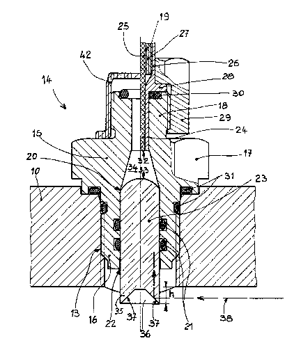
Figure 2 is an enlarged scale view of the detector according to
figure 1, represented in the right-hand half-view coupled to the
optic fiber and in the left-hand half-view before coupling of
the fiber.
DESCRIPTION OF THE PREFERRED EMBODIMENT
In the figures a busbar of a metalclad substation comprises a
sealed enclosure with a cylindrical wall 10, filled with a high
dielectric strength gas, such as sulphur hexafluoride, and
containing a conducting bar 11, coaxially supported by support
insulators 12 located at intervals along the bar 11. In a
threaded orifice 13, arranged in the wall 10 of the enclosure or
in a sleeve welded to this wall there is screwed an arc detector
14, passing tightly through the wall 10. The detector 14 is
formed by an adaptor 15 having a threaded front part 16, which
screws into the wall 10, an intermediate collar 17 with a
hexagonal gripping head and a threaded rear part 18 for screw
connection of an optic conductor 19. The adaptor 15 has passing
through it an axial passage 20 accommodating in the rear part 16
a rod 23 made of glass or transparent synthetic insulating
material, tightly sealed by two O-rings 21 and/or by sticking
22. In the rear part 18 of the passage 20 of smaller cross-
section there is fitted in alignment with the rod 23 the bared
end 24 of an optic fiber 25. The optic conductor 19 is fixed by
means of a sleeve 26 fitted over the bared end 24 and over a
section of the sheath 27 of the fiber 25. This sleeve 26 has a
collar 28 held against the face of the rear part 18 by a nut 29,
screwed onto this threaded rear part 18. An O-ring 30 is
inserted between the collar 28 and the bearing face 18. The
tightness between the adaptor 15 and wall 10 is achieved by
O-rings 31 in the usual way. Between the ter~inal face 32 of the

203~
optic fiber 25 and the rounded end 33 of the rod 23 facing it
there is arranged a frustum-shaped connecting gap 34. The metal
adaptor 15 is, in the fixing position of the arc detector 14,
slightly away from the wall 10 ln order not to disturb the
electrical insulation, whereas the rod 23 protrudes out from the
adaptor 15 and the wall 10 penetrating over a reduced height h
inside the enclosure. This slight protuberance of an insulating
part 23 does not affect the dielectric withstand.
In the example illustrated by figure 2, the rod 23 is of
cylindrical cross-section and the protruding internal end 35 has
a frustum-shaped internal cavity in the form of a funnel 36
whose depth corresponds appreciably to the protrusion height h.
The frustum-shaped faces 37 are inclined approximately 45 on
the axis of the rod 23 and constitute reflecting faces of a
light ray 38, notably a ray parallel to the wall 10, which is
deviated through 90 in the direction of the axis of the rod 23
towards the optic fiber 25. The rod 23 also captures rays
oriented differently, in parti~ular along the axis of the rod
23.
The optic conductor 19 is connected to a processing device 39,
which can be common to several sensors 14 and which transforms
the light signals transmitted by the optic conductors 19 into a
tripping or fault indication order 40. By providing orifices 41
in the support insulators 12 for the light rays 38 to pass
through, a single sensor 14 can monitor several compartments of
the busbar or enclosure. It can be understood that the rays 38,
emitted from a point far from the sensor 14, are appreciably
parallel to the wall 10 and strike the rod 23 perpendicularly.
The reflecting faces 37 capture these rays 38 which would simply
pass through the rod 23 if such faces 37 were absent. The
reflecting faces 37 can be in convex protrusion and/or be formed
by facettes or plane faces oriented along the axis of the bar
11. The sensor 14 is advantageously secured to the upper wall 10

~G~ 7~
so as to face downwards and to avoid deposits forming a screen
preventing the light from passing. The rod 23 is preferably made
of transparent plastic material, but other materials can be used
and the connection between the rod 23 and the optic fiber can be
achieved by abutment of the two facing ends 32, 33. The optic
conductor 19 of standard type can easily be fitted or removed
after the nut 29 has been unscrewed. The left-hand part of
figure 2 shows the sensor 14 before connection of the optic
conductor 19 with a protective cover 42 screwed onto the rear
part 18 in order to avoid damage during transport. After the
substation has been assembled the cover 42 merely has to be
removed and the optic conductor 19 fitted by inserting the end
24 and tightening the nut 29.
The sensor 14 hardly penetrates inside the enclosure and can
therefore be fixed at any point, wherever is most suitable. A
limited number of sensors 14 and therefore of orifices 13 in the
wall 10 allows full monitoring of the whole installation. The
cross-section of these orifices 13 can be small and the
tightness and fixing of the rod 23, which passes perpendicularly
through the wall 10, can naturally be achieved differently.

Dessin représentatif
Une figure unique qui représente un dessin illustrant l'invention.
États administratifs

2024-08-01 : Dans le cadre de la transition vers les Brevets de nouvelle génération (BNG), la base de données sur les brevets canadiens (BDBC) contient désormais un Historique d'événement plus détaillé, qui reproduit le Journal des événements de notre nouvelle solution interne.

Veuillez noter que les événements débutant par « Inactive : » se réfèrent à des événements qui ne sont plus utilisés dans notre nouvelle solution interne.

Pour une meilleure compréhension de l'état de la demande ou brevet qui figure sur cette page, la rubrique Mise en garde , et les descriptions de Brevet , Historique d'événement , Taxes périodiques et Historique des paiements devraient être consultées.

Historique d'événement

Description Date
Inactive : CIB de MCD 2006-03-11
Le délai pour l'annulation est expiré 2002-02-25
Demande non rétablie avant l'échéance 2002-02-25
Réputée abandonnée - omission de répondre à un avis sur les taxes pour le maintien en état 2001-02-26
Lettre envoyée 1998-03-03
Inactive : Renseign. sur l'état - Complets dès date d'ent. journ. 1998-03-02
Inactive : Dem. traitée sur TS dès date d'ent. journal 1998-03-02
Exigences pour une requête d'examen - jugée conforme 1998-02-09
Toutes les exigences pour l'examen - jugée conforme 1998-02-09
Demande publiée (accessible au public) 1991-08-27

Historique d'abandonnement

Date d'abandonnement Raison Date de rétablissement
2001-02-26

Taxes périodiques

Le dernier paiement a été reçu le 2000-01-28

Avis : Si le paiement en totalité n'a pas été reçu au plus tard à la date indiquée, une taxe supplémentaire peut être imposée, soit une des taxes suivantes :

  • taxe de rétablissement ;
  • taxe pour paiement en souffrance ; ou
  • taxe additionnelle pour le renversement d'une péremption réputée.

Les taxes sur les brevets sont ajustées au 1er janvier de chaque année. Les montants ci-dessus sont les montants actuels s'ils sont reçus au plus tard le 31 décembre de l'année en cours.
Veuillez vous référer à la page web des taxes sur les brevets de l'OPIC pour voir tous les montants actuels des taxes.

Historique des taxes

Type de taxes Anniversaire Échéance Date payée
TM (demande, 7e anniv.) - générale 07 1998-02-25 1998-01-23
Requête d'examen - générale 1998-02-09
TM (demande, 8e anniv.) - générale 08 1999-02-25 1999-01-28
TM (demande, 9e anniv.) - générale 09 2000-02-25 2000-01-28
Titulaires au dossier

Les titulaires actuels et antérieures au dossier sont affichés en ordre alphabétique.

Titulaires actuels au dossier
MERLIN GERIN
Titulaires antérieures au dossier
ANDRE GIBOULET
ANTONIO CODAZZI
BRUNO MAFFIOLETTI
ETTORE GIUDICI
MASSIMO ALLEVI
Les propriétaires antérieurs qui ne figurent pas dans la liste des « Propriétaires au dossier » apparaîtront dans d'autres documents au dossier.
Documents

Pour visionner les fichiers sélectionnés, entrer le code reCAPTCHA :


Pour visualiser une image, cliquer sur un lien dans la colonne description du document. Pour télécharger l'image (les images), cliquer l'une ou plusieurs cases à cocher dans la première colonne et ensuite cliquer sur le bouton "Télécharger sélection en format PDF (archive Zip)" ou le bouton "Télécharger sélection (en un fichier PDF fusionné)".

Liste des documents de brevet publiés et non publiés sur la BDBC .

Si vous avez des difficultés à accéder au contenu, veuillez communiquer avec le Centre de services à la clientèle au 1-866-997-1936, ou envoyer un courriel au Centre de service à la clientèle de l'OPIC.


Description du
Document 
Date
(aaaa-mm-jj) 
Nombre de pages   Taille de l'image (Ko) 
Abrégé 1994-03-30 1 12
Revendications 1994-03-30 2 41
Dessins 1994-03-30 2 46
Description 1994-03-30 5 177
Dessin représentatif 1999-07-25 1 29
Rappel - requête d'examen 1997-10-24 1 117
Accusé de réception de la requête d'examen 1998-03-02 1 179
Courtoisie - Lettre d'abandon (taxe de maintien en état) 2001-03-25 1 182
Taxes 1996-01-25 1 67
Taxes 1995-01-24 1 71
Taxes 1997-01-22 1 65
Taxes 1994-01-24 1 55
Taxes 1993-01-19 1 60