Note : Les descriptions sont présentées dans la langue officielle dans laquelle elles ont été soumises.
2~3~7~L9
ENGINE STARTER GEARIN~
BACKGROUND ~ T}IE INVENTION
1. FIELD OF T~IE INVENTION
The present invention generally relates to engine starter gearing
for an engine. More speeifieally, this invention relates to engine sta~ter
gearing of a positive shift type, including a dentil clutch to provide
driving and overrunning features and further including provisions for
effeeting the automa-tic separation of the clutch tee-th after the engine
heeomes self-running.
1~ 2. DESCRIPTION OF T~IE PRIOR ART
The present invention is an improvemen~ over V.S. Pa-tent No.
4,611,499 entitled "Engine Star-ter ~earing", issued September, 19~6, to
Giomet-ti, and assigned to the assignee hereof, as well as a fur-ther
improvement over the starter gearing system deseribed in U.S. Patent No.
3,~63,509 entitled "Engine Starter Drive", issued August 2, 1966, to Digby.
The Digby patent diselosed an engine star-ter gearing using
eentrifugal weights and a conical thrust washer for separating dentil elutch
teeth a~ter engine start-up to prevent long periods of eluteh overrunning
and aceompanying dele-terious wear on the clutch teeth. An anmllar recess is
formed in a driving eluteh member. A eireular reeess is provided in the
faee of a driven eluteh member faeing the driving elu-tch member. An annular
thrust washer is fitted in the annular recess and abuts the driving clutch
member. A conieal surface is provided on -the annular thrust washer facing
the driven cluteh member.
A plurality of centrifugal flyweight members are also provided in
the circular recess. The eentrifugal flyweight members are provided with an
inelined surf~ee cooperating with the eonical surface in the annular -thrust
washer, sueh that, when an overrunning eondition occurs, the centrifugal
flyweight members move radially outwardly and the inclined surface engages
I
2~87~
the conical s~rface of the annular thrus-t washer so as to bias -the driving
clutch member away from the driven clu-tch member. The centrifugal flyweight
members are prevented from a~ial or ro-tational movement with respect to the
driven clutch member by pins extending through sui-table bores in the driven
clutch member and the centrifugal flyweight member.
While the engine starter gearing of Digby has been satisfactory in
operation, it is difficult and expensive to assemble. This is true because
a plurality of movable pins and centrifugal flyweight members must be
somehow maintained in position rela-tive -to the driven clutch member during
tha assembly of the driven clutch member to the driving clutch member.
Furthermore, the weight and, therefore, the effectiveness of the
centrifugal flyweight members is reduced by the existence of a substantial
bore therethrough, in comparison to the size of the centrifugal flyweight
member, for admission of the pin. The bore through the cen-trifugal
flyweight members further reduces the strength of the flyweight members and,
accordingly, limits the materials and dimensions which may advantageously be
used for the centrif~gal flyweight members.
The embodiment of Figures 3 and 4 of IJ.S. Pa-tent No. 4,611,499 to
Giometti solved many of the aforementioned engine starter gearing
2D disadvantages, but such an embodiment requires the llse of a driven clutch
member whose circular recess is difficult to machine. As solutions thereto,
U.S. Patent No. 4,712,435 to Losey et al, U.S. Patent No. 4,768,392 to
Giometti, and U.S. Patent No. 4,8~3,897 to Tallis Jr. disclosed various
forms of annular inserts. Each of the disclose(l annular inserts provided
rlyweight guides for guiding the flyweight members when they travel radially
as a result of a centrifugal force produced during an overrunning condition.
As such, the use of the annular inserts eliminated the requirement for
precislon machining o' the circular recess of -the driven clutch member.
. .
2~387~
However, in practice it has been determined that the flywei~ht
guides of the latter patents ci-ted are not adapted to limit the axial travel
of the flyweight members as could the pin arrangement taught by ~igby. As a
consequence~ during the overrunnirlg condition the annular -thrust washer can
at times be forced back sufficiently by the interaction of the inclined
surface of the flyweight members with the conical surface of the annular
thrust washer to allow the flyweight members to travel axially toward the
annular thrust washer until the flyweight members are beyond the flyweight
guides. The flyweight members are then able to escape the flyweight guides
and migra-te circumferentially around the perimeter o~ the circular recess of
the driven clutch member. Testing has indicated that this phenomenon
results in momen-tary slipping between -the driving and driven clutch members,
causing high peak torques which are capable of twisting the mounting shaft
splines.
Therefore, what is needed is an improved engine stnrter gearing
using a centrifugal flyweight clutch separator which is capable of retaining
the flyt~eight memhers as they travel in both the radial and a~ial directions
such that the flyweight members are prevented from circumferentially
migra-ting around the circular recess of -the driven clutch member under all
operating condiSions. Furthermore, what is needed is such an engine starter
8eariDg having a more solid~ compact, and durable configula-tion ~or the
centrifugal flyweight member which simplifies the manufacturing opera-tions
]nvolved in manufacturing such engine starter gearing, particularly in
regard to $he driven clutch member component -thereof.
SUMMARY OF THE INVENTION
The present invention provides a novel and improved engine starter
gearing having a ceDtrifugal weight clutch separator with solid unitary
centrifugal flyweight members which can be readily manufactured and
assembled $o the engine st~rter gearing. Of primary importance, the engine
~3~7~
starter gearin8 of the presen-t invention provides longi-tudinal projections
which, in conjunction with retaining surfaces associated with the driven
clu-tch member, are capable of fully retaining the Plyweight members as they
travel in -the axial direc-tion. The flyweight members are thereby prevented
from circumferentially mi~rating around the circular recess of the driven
clutch member under all foreseeable operating conditions.
ln particular, the engine ~tarter gearing o~ the present invention
provides a power shaft, a sleeve slidably secured to the power shaft, and
helical ~plines on one extremi-ty of the sleeve. A pinion gear is slidably
journaled to the power shaft for axial movement relative thereto, the pinion
gear being structured for movement into and out of engagement with the
starting gear of the engine to be started. A driven clutch member is
secured to the pinion gear for movement therewith. A circular recess is
located in the driven clutch member. A driving clutch member is slidably
mounted on the helical splines of the sleeve. The driving and driven clutch
members have complementary :utually engageable inclined teeth for
transmitting torque therebetween in one direction of relative rotation.
A housing is s;lidably suppor-ted on the sleeve and is provided with
an open end such that the barrel housing may be fi-t-ted over the driving and
driven clutch members. The driving and driven clu-tch members are contained
within the housing by abutment means. A resilient member is disposed within
the housing and abuts the driving clutch member so as to bias -the driving
clutch member against the driven clu-tch member, thereby engaging the
mutually engageable inclined teeth of the driving and driven clutch members.
25 ~ A radially in~ardly ex-tending shoulder is formed on the driving clutch
member adjacent -the recess formed in the driven clutch member. An annular
thrust ring having an inner conical surface is loosely disposed in the
circular recess in the driven clutch member. The annular thrus~ ring is
:
2~3~
J
structured to abut the radially inwardly extending shoulder of the driving
clutch member when displaced in a first direction.
A plurali-ty of centrifugal fIyweight members are annularly
arranged in the circular recess in the driven clutch member. The plurality
of centrifugal flyweight members each h~ve an inclined surface abu-tting the
conical surface of -the annular thrust ring. The plurali-ty of centrifugal
flyweight members are operative to displace the annular thrust ring in a
first axial direction in response to the centrifugal force.
A plurality of cavities are formed in an annular sleeve which is
inserted into the circular recess of the driven clutc}1 member. The annular
sleeve is provided to be non-rotatable relative to the driven clutch member.
Each of the cavities has a pair of retaining surfaces which extend
longitudinally in relation to the power shaft axis and which slidably
receive -therebetween at least a portion of i-ts associated centrifugal
flyweight member to prevent its circumferential movement while permitting
radial movement thereof.
In the preferred embodiment of the present invention, the annular
~leeve is provided with long1tudinal projections extending from each of the
longltudinal retaining surfaces and -toward -the annu1ar thrust ring. The
projections ensure circumferential restraint of each of the flyweight
members when at the extreme limit of their longitudinal -travel towards the
annular thrust ring.
Accordin~ly, i-t is an object of the present invention to provide
an engine starter gearing having a centrifugal flyweigh-t clutch separator
in which the flyweight members are prevented from migrating
circumferentially from their containment cavities when -the flyweight members
are at the extreme limit of their longi-tudinal travel capability. The
present invention accomplishes this object by providing a plurality of
longitudinal projections formed integrally with an annular sleeve which
2 ~ 3 ~ ril a~ ~
resides within the driven clu-tch member. The annlllar sleeve retains each of
the flyweight members within a cavity which allows limited radial
displacement during an overrunning condition in the operation of the engine
starter gearing, but does not restrain the flyweight members from being
longitudinally displaced. The longitudinal projections are of sufficient
leng-th such that at the extreme longitudinal limit of the flyweight members'
travel, the flyweight members remain retained within their respective
cavities and are unable to migrate out between the driving clu-tch member and
the driven clutch member.
It is a further objec-t of this invention to provide an engine
starter gearing which is easy to assemble. The present invention
accomplishes this object by providing a plurality of unitary centrifugal
flyweight members each directly engageable with an annular sleeve within the
driven clutch member so as to reduce the number of components which must be
secured -together during assembly and reduce the complexity of the
fabricating steps that must be followed to properly manu~acture such
components.
It is still a further object of this invention -to provide engine
starter gearing having a centrifugal flyweight clutch separator with strong
centrifugal flyweight members. The present invention satisfies this object
by providing unitary flyweight members without cavities formed therein, such
that the flyweight members may be formed of a wide varie-ty of available
materials.
Other objects and advantages of -this invention will be more
apparent after a reading of the Eollowing detailed description taken in
conjunc-tion with the drawings provided.
BRIEF DESCRIP~IO~ OF THE DRAWINGS
Figure 1 is a side elevational view, partly broken away and partly
in section, of the preferred embodiment of structure for an engine starter
gearing according to the present invention;
Figure 2 is an enlarged fragmentary view of the engine starter
gearing shown in Figure 1;
Figure 3 is a cross-sectional view along line 3-3 of Figure 1 at a
somewhat enlarged scale relative to that of Figure 1;
Figure 4 is a side elevational view, par-tly in section, of the
driven clutch member according to the present invention;
Figure 5 is an end view of the driven clutch member along line
5~5 of Figure 4;
Figure 6 is a cross-sectional end view of the flyweigh-t retainer
according to the present invention;
Figure 7 is a cross-sectional side view of the flyweight retainer
along line 7-7 of Figure 6;
Figure 8 is a perspective view of the flyweight retainer of the
~ present invention;
Figure 9 is a partial cross-sectional side view of an alternate
embodiment of the pinion gear; and
Figure 10 is a cross-sectiGnal end view of the pinion gear taken
in the direction of arrows 10-10 of Flgure 9.
DETAILED DE~CRIPTION OF THE PREFERRED EMBODIMENT
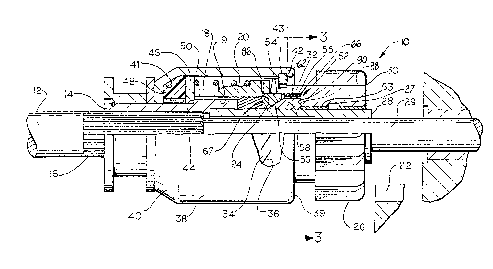
Re~erring to Figure 1, there is provided a star-ter drive 10 for an
engine (not shoan) mounted to a power shaft 12 of a starting motor (not
shown). The starter drive 10 includes an axially extending sleeve 14
connected to the power shaft 12 by s-traight splines 16. The axially
: extending sleeve 14 is, -therefore, axially bu-t not rotatively movable
relative to the power shaft 12~ The external surface of -the right-hand
extremity of the axially extending sleeve 14, as illustrated, has external
hellcal splines 18 formed thereon. A driving clutch member 20 has internal
helical splines 19 threaded onto the external helical splines 18 of -the
axially extending sleeve 14. The driving clu-tch member 20 is, therefore,
2 ~ 3 r7 ~L 9
adapted for movemerlt -towarcls and way from a starting gear 22 of the engine
to be started.
The driving clutch member 20 is illustrated in its engaged
position in the drawing, In the engaged posi-tion, the driving clu-tch member
20 projects past the right end of the axially extending ~leeve 14. The
rightmost edge, as illustrated, of -the internal helical splines 19 of the
driving clu-tch member 20 form a radially inwardly extending shoulder 24, for
a purpose to be described later.
A sleeve 28 is slidably supported on a reduced diameter portion 29
of the power shaft 12. One end of the sleeve 28 i5 secured to the axially
extending sleeve 14. A pinion gear 26 is journaled on a bearing 63 which is
press fit into the pinion gear 26. A lubrication groove 27 is located
between the sleeve 28 and the bearing 63. The bearing 63, in -turn, is
slidably mounted on the sleeve 2B thereby permitting the pinion gear 26 to
be axially and rotatably movable rela-tive to the power shaft l2. The pinion
gear 26 is structured for movement into and out of engagement with the
starting gear 22 of tbe engine to be started.
A driven clutch member 30 is integrally formed with the pinion
gear 26 and extends therefrom towards the driving clutch member 20. An
internal circular recess 32 is provlded in -the driven clutch member 30
adjacent the driving clutch member 20. The internal circular recess 32
cooperates with the sleeve 28 to define an anmllar channel therebetween.
The adjacent faces of the driving clutch member 20 and driven
clutch member 30 are provided with dentil -teeth 34 and 36, respectively,
which are complementary mutually engageab1e inclined torque transmitting
dentil teeth. The dentil teeth 34 and 36 are o~ the sawtooth variety to
provide a one-~ay overrunning clutch connec-tion.
A housing 38 having an open end 39 and a closed end 40 is slidably
supported at its closed end 40 on an ex-ternal surface of the a~ially
extending sleeve 1~. The hous;ng 38 i.s barrel-shaped ancl fitted over -the
driv;ng clutch member 20 and partially over the driven clu-tch member 30. A
lock r;ng 42 is seated in a groove 43 adjacent the open encl 39 of the
housing 38. The lock ring ~2 has su~ficient radial length to engage the
driven clutch member 30 to thereby confine the driverl clutcll member 30 and
the driving clutch member 20 within a cavity 4] of the housing 38.
The axially extending sleeve 14 is provided with a radial shoulder
in an intermedia-te location therealong to provide an abu-tment for a disk
or washer 46 slidably Journaled on the axially extellding sleeve 14. A
resiliently yieldable annular member ~8, preferably formed of an elastically
deformable ma-terial, such as rubber, is compressively confined between the
washer 46 and the closed end 40 of the housing 38. A resilienk spring
member 50 is compressively confined within the cavity 41 o~ the housing 38
between the washer ~6 and the driving clutcll member 20 to provide a biasing
force urging the driving clutch member 20 into engagement with the driven
clutch member 30.
An advancement apparatus, not illustrated in the drawings bu-t well
known in the art, is provided for moving the starter drive 10 towards and
away from the starting gear 22 of the engine.
The starter drive 10 is provided wi-th a centrifugal flyweight
clwtch separator assembly, generally indicated by reference nu~eral 52, to
effect disengagement of the driving clutch member 20 from the driven clutch
member 30 when the engine is running above a predetermined speed. The
centrifugal flyweight clutch separator a~sembly 52 thereby avoids excessive
wear of the mutually engaging dentil clutch teeth 34 and 36.
The centrifugal flyweight clutch separator assembly 52 includes an
annular thrust washer 5~ disposed within -the in-ternal circular recess 32.
Located between the annular thrust washer 54 and the anmllar shoulder 24 of
the driving clutch member 20 is a loose thrust washer 67. A sleeve-like
2~3~
flyweight retainer 55 is also retained in the interDal circular recess 32,
forwardly of the annular thrust washer 5~. It is preferred that the
flyweight retainer 55 be cons-tructed of molded plastic.
As seen in Figures 2 and 3, an ou-ter surface 60 of the flyweigh-t
retainer 55 is provided with a circumferential plurality of spl;nes 62 which
en~age a complementary circumferential plurality of splines 66 on an inside
surface 64 of the driven clutch member 30 to accura-tely circulnferentially
orien-t and retain the flyweight re-tainer 55 with respect to the driven
clutch member 30. As can be seen from Figure 4, tlle splines 66 formed on
the inside surface 64 of the driven clutch member 30 are located ad~acent
the dentil teeth 36. The inside surface 64 is generally circular and the
splines 66 are preferably formed as shallow splines similar to a serrated or
knurled surface.
The flyweight retainer 55 is annularly dimensioned to be inserted
into the internal circular recess 32 of the driven clutch member 30 so that
the outer surface 60 of the flywei~ht retainer 55 abuts the inside surface
64 of the driven clutch member 30. As can be seen from ~igure 6, the
plurali-ty of splines 62 are provided on the outer surface S0 of the
flyweight retainer 55. These splines are complementary to the splines 66 on
: 20 the inside surface of the driven clutch member and are preferably formed as
shallow splines similar to a serrated or knurled surface.
: In order -that the flyweigh-t retainer 55 be insertable in-to the
internal circular recess 32 of the driven clutch member 30 and located
against a base surface 90, and yet be of sufficient cross-section so that
its splines 62 may engage the splines 66 on the inside surface of the driven
clutch member 30, the flyweight retainer 55 is provided with a slot 70 which
permits it to be deformed during insertion into the driven clutch memher.
The slot 70 is located between spaced apart recesses 55al as bes-t shown in
Figure 6. The flyweight retainer 55 is made of a s-tructurally strong yet
rJ ~ ~3
resilient material, such as a s-tructural plastic which permits deformation
su~ficient to seat the flyweight retainer 55 within the clriven clutch member
~0 and resume i-ts original shape once it is seated -therein.
In the preferred embodiment of the present invention, the splines
~ on the inside surface 64 of the driven clu-tch member 30 are located in a
central portion 73 of the insicle surface of -the interl-al circular recess 32.
Accordingly, once the flyweight retalner 55 is seated within the internal
circular recess 32 against the base surface 90, the engagement of the
splines 62 and 66 will cause the flyweight retainer 55 to be retained within
-the dr;~en clutch member 30.
The flyweight retainer 55 also is provided on its inside surface
with a circumferential series of the spaced-apart recesses 55a, as shown in
Figures 3 and 6. ~ach recess 55a has a first and second retaining surface
82 and 84, respectively, which ex-tend longitudinally in relation to the axis
~5 of the power shaft 121 the first and xecond retaining surfaces 82 and 8
being parallel to each other. As best seen in Figure 7, a longitudinal
projection 85 extends longitudinally from each of the first and second
retaining surfaces 82 and ~4 toward the driving clutch member 20 such that
eal-h longitudinal projection 85 is coplanar with i-ts corresponding first
retaining surface 82 or second retaining surface 84. The longitudinal
projections 85 act as continuous ex-tensions of -the first and second
retaining surfaces 8~ and 84 in the longi-tudinal direction of the flyweight
retainer 55 for a purpose to be described later.
A plurality of centrifugal flyweight members 58 are fitted in the
spaced-apart recesses 55a of the flyweight retainer 55. A portion of each
of -the centrifugal flyweight members 58 extends in-to one of the spaced-apart
recesses 55a. In fact, the major portion of each of the centrifugal
flyweight members 58 is disposed within each of the spaced-apart recesses
55a.
11
2~3~7~9
As can be s0en fro~ Figures 2 and 3, each of the centrifugal
~lyweight members 58 is appropriately dimensiorled for cooperation with the
spaced-apart recess 55a in which it is loca-ted. Each of the centrifugal
flyweigh-t members 58 is also appropriately dimensioned for cooperation with
a conical inner sur~ace 56 of the annular thrust washer 54. Each spaced-
apart rccess 55a has an inside surface 68 which is spaced from the
centrifugal flyweight member 58 so that the centrifugal flyweight member 58
can reciprocate radially, as will be explained below. Thus, each of the
centrifugal flyweigllt members 58 has an inner surface 72 engaging -the outer
surface of the sleeve 28 and an outer ~urface 74 remote from the inner
surface. Pre~erably, the inner surface 72 and the outer surface 74 are
circular, cylindrically shaped, and concentric.
A first and second guide surface 76 and 78, respectively, are
formed betwee~ the inner surface 72 and the outer surface 74 of each of the
centrifugal flyweight members 58. The firs-t and second guide surfaces 76
and 78 are flat and parallel to each other. Pre~erably, they are parallel
to a radial plane 80 through the center of gravit~ of the centrifugal
flyweigh-t members~ The first and second guide surfaces 76 and 78 cooperate
uith the first and second retaining surfaces 82 and 84 of the recesses 55a
2D of the annular flyweight retainer 55 -to guide the axial and radial
reciprocal motion of the centrifugal ~ly~eight members 58. Further, the
first and second retaining surfaces 82 and 84 retain the centrifugal
flyweight ~embers 58 in the circumferen-tial direction when the dentil clutch
teeth 34 and 36 are engaged.
Each of the centrifugal flyweight members 58 is also provided with
an inclined surface 86 extending inwardly and angularly away from the ou-ter
surface 74 towards -the inner surface 72 thereof. The inclined surface 86
cooperates with the conical inner surface 56 of the annlllar thrust washer 54
to separa-te the den-til teeth 34 and 36? respectively, of the driving clutch
12
2~8~
member 20 and the driven clutch member 30 during an overrunning condition.
The centrifugal flyweight menlbers 58 are also provided with a third guide
surface 88 disposed remote from the inclined surface 86 and ex-tendin~
perpendicular to each o~ the first and second g~ide surfaces 76 and 78
between the inner sur~ace 72 and the outer surface 74. Tlle third guide
surface 88 cooperates with the base surface 90 of the internal circular
recess 32. The base surface 90, therefore, acts as an abutment during the
radial out~ard motion of the centrifugal flyweight members 58.
In operat;on, when it is desired to crank the engine, the starter
drive 10 is shifted to the right via the shifting mechanism, not
illustrated, so that the pinion gear 26 engages the starting gear 22. The
power shaft 12 i~ ro-tated by a starting motor, not illustrated, and
transmits torque through the straight splines 16 to -the axially extending
sleeve 14, and from the helical external splines 18 -to -the driving ckltch
member 20. The driving clutch member 20 drives the driven clutch nlember 30
through the dentil -teeth 34 and 36. The driven clutch member 30 -thereby
rotates the pinion gear 26 and the star-ting gear 2. of the engine~
~ As the engine fires and becomes self-operating, the star-ting gear
: 22 will drive the pinion gear 26 at a speed greater than that of the power
shaft 12. The dentil teeth 34 and 36 will slip so tha-t the starting motor
is not driven at a high engine speed. In order to protect the dentil teeth
34 and 36 from severe wear due to the rubbing and clashing which would
otherwise occur, and further to avoid unnecessary noise, the rapid rotation
of the driven clutch member 30 drives the centrifugal flyweigll-t members 58
radially outwardly. The movement of each centrifugal flyweight member 58 is
guided by the corresponding first and second retaining surfaces 82 and 84 of
~ne of the recesses 55a of the annular flyweight re-tainer 55 so as to
prevent any motion of the centrifugal ~lyweigh-t members 58 relative to the
driven clutch member 30 o-ther -than the desired radial motion.
13
~38~
The radially outward motion of the centrifugal flyweight members
68 will bring -the inclined surface 86 of the centri~llgal flyweight members
58 into engagement with the conical inner surface 56 of the annular thrust
washer 54, urging the annulhr thrust washer 54 to the left against the
biasing force of the resilient spring memher 50, as illustrated in Figure 1.
This motion of the annular thrust washer 54 is transferred through the loose
thrust washer 67 to the raclially inwardly extending shoulder 2~ of the
driving clu-tc}l member 20, causing a separation between the driving clutch
member 20 and the driven clutch member 30.
Of primary concern ~or purposes of the present invention, it is
possible during the above overrunning condition ~or the centri~ugal
flyweight members 58 to migrate longitudinally toward -the driving clutch
member 20 and beyond the first and second retaining surfaces 82 and 84,
which under non-overrunni.ng conditions re-tains the centrifugal flyweight
members 58 in the circumferential direction. For this reason, the
longitudinal projections 85 ex-tend sufficiently from their respective first
and second retaining surfaces 82 and 84 such tha-t the centrifugal flyweigh-t
members 58 renlain retained within their respective recesses 55a even when at
their extreme longi-tudinal limit of travel. Consequently, the centrifugal
flyweigh-t members 58 are incapable under any condition oP moving
circumferentially between the driving clutch member 20 and the driven clutch
member 30, which would otherwise result in momentary slipping between the
driving and driven c].u-tch members 20 and 30, causing high peak torques which
are capable Oe twisting the s-traight splines 1~
The starter drive 10 disclosed above has certain additional
advantages over the prior art. It w;.:ll be readily appleciated by those
skilled in the art -that the centrifugal ~lyweigh-t members 58 are extremely
easy and inexpensive to form, as compared witll the prior art centrifugal
Elyweight members for starter drive gearing. Furthermore, the centri~ugal
14
2~38~4~
flyweight members ~8 are very strong and may be formed from materials which
might even be inappropriate for the centrifugal ~lyweight members 58
described previously, thereby ~urther increasing the number o~ materials
which may be selected from for manu~acturing this component.
Furthermore, preoise dimensions may be provide~ in the ~eoesses
that are used to retain the flyweight members through the use of a molded
plastic ~lyweight retainer 55 containing the r~cesses 55a) which thereby
eliminates the need to resort to complex machining or cold-forming
operations in an effort to ~orm such precisely dimensioned recesses directly
in the driven clutch member 30, which is normally formed from a hard metal
because of the loads and wear that it is subjected -to in normal service.
Importantly, because complementary splines are pro~ided on both
-the outer surface of the flyweight retainer and -the inside sur~ace of the
driven clutch member, there is no need to ~urther machine the driven clutch
member in order to provide ~or holding of the ~lyweight retainer; the
splines may be rolled on during the machining process without re~uiring
special tools or manufac-turing processes. The ~lyweight retainer 55 is
pre~erably ~ormed Prom a hard, dimensionally resilient and stable
thermoplastic material, such as a Nylon (polyamide) based material, and t:he
~0 ~lyweight retainer may be readily and inexpensively mass-produced from such
a thermoplastic material by conventional injection molding practices and
equipment.
In an alternate embodiment o~ the engine starter gearing, the
pinion gear 26, driven clutch member 30, and the flyweight retainer 55 may
~5 be ~ormed as an in-tegrated pinion gear 100 as shown in Figures 9 and 10.
The integrated pinion gear 100 has a cylindrically-shaped sleeve portion 102
having a pinion gear 10~ ~ormed at one erld which corresponds to the pinion
gear 26 shown in Figure 1, and dentil teeth 106 provided at the opposite end
which correspond to the dentil -teeth 36. The in-tegrated pinion gear ~00 has
~38~
an axially disposed bearing bore 108 into WhiC}I the sleeve bearing 63 ;s
press fit. As describecl relat;ve to Figure 1, the integrated pinion ~ear
100 with -the bearing 63 press fit into the bearing bore 108 is journaled on
the sleeYe 28. The internal surface of the bearing bore 108 may be grooved
or serratedl as is known in the art, to facilitate the locking of the
bearing 63 in the bearing bore 108.
Three equally spaced longitudinal flyweight recesses 110 are
formed in the end of the slee~e portion 102 opposi-te the pinion gear 104.
The flyweight recesses ltO are bounded on opposite sicles by substantially
parallel retaining sur-faces 112 and l14 which extend longitudinally parallel
to the axis of rotation 116 of the integrated pinion gear 100. The
flyweight recesses 110 are s-tructurally and func-tionally equivalent to the
recesses 55a of -the flyweight retainer 55 shown in Figure 8. Intermediate
the retaining surfaces 112 and 114 is a longitudinally extending flyweight
abutment surface 118 which limits the radial displacement of the flyweight
members 58 due to centrifugal forces. Preferably the flyweight abutmen-t
surfaces 118 have an arcuate cross section as shown ln Figure 10 having a
center of curvature concentric with the axis of rotation 116. The retaining
surfaces 112 and 114 and the flyweight abutment surfaces 118 -terminate at a
: 2D radially disposed base surface 126 formed at -the end of each flyweight
recess 110.
The flyweight recesses 110 are separated from each o-ther by a web
120 bolmded on opposite sides by the retaining surfaces 112 and 114. Each
web 120 has a longitudinal projection 122 which corresponds to the
; 25 projections 85 of the flyweight retainer 55 shown in Figures 6 through 8.
Ex-ternal surfaces 124 of the longitudirlal projections 122 incline toward the
axis of rotation 116 and are segmen-ts of a -truncated cone which mates with
the conical inner surface 56 of the thrust washer 5/1. Thus when the dentil
teeth 106 of the integrated pinion gear 100 are meshed with the dentil teeth
l6
2~387~
34 of the driven member 20, -the conical inner surface 56 of the thrust
washer 54 circumscribes the longitudinal projec-tions 122 Oe the webs 12Q.
As discussed relative to the emhodiment shown in Figures 1 -through
8, the primary function of the projections 122 of the webs 120 is to retain
the flyweight members 58 in their respective flyweight recesses 110 during
an oYerrunning condition. The projections 122 prevent the ~lyweight members
58 fr~m migrating in a longitudinal direction beyond the retaining surface~
112 and 114 even when they are at their extreme longitudinal limit.
Consequently, the flyweight members 58 are incapable under any condition of
moving circumferen-tially be-tween the driving member 20 and the integrated
pinion gear 100 and preventing re-engagement of the dentil teeth 34.
While the invention has been described in terms o~ a preferred
embodiment, it is apparent that other forms could be adopted by one skilled
in the art. Accordingly, the scope of the invention is to be limited only
by the following claims.
~hat is claimed is:
17