Sélection de la langue

Search

Sommaire du brevet 2039498 

Énoncé de désistement de responsabilité concernant l'information provenant de tiers

Une partie des informations de ce site Web a été fournie par des sources externes. Le gouvernement du Canada n'assume aucune responsabilité concernant la précision, l'actualité ou la fiabilité des informations fournies par les sources externes. Les utilisateurs qui désirent employer cette information devraient consulter directement la source des informations. Le contenu fourni par les sources externes n'est pas assujetti aux exigences sur les langues officielles, la protection des renseignements personnels et l'accessibilité.

Disponibilité de l'Abrégé et des Revendications

L'apparition de différences dans le texte et l'image des Revendications et de l'Abrégé dépend du moment auquel le document est publié. Les textes des Revendications et de l'Abrégé sont affichés :

  • lorsque la demande peut être examinée par le public;
  • lorsque le brevet est émis (délivrance).
(12) Demande de brevet: (11) CA 2039498
(54) Titre français: PINCE MONIPIECE EN PLASTIQUE, POUR SERVIETTE
(54) Titre anglais: ONE-PIECE PLASTIC TOWEL CLAMP
Statut: Réputée abandonnée et au-delà du délai pour le rétablissement - en attente de la réponse à l’avis de communication rejetée
Données bibliographiques
(51) Classification internationale des brevets (CIB):
  • F16B 02/10 (2006.01)
  • A44B 99/00 (2010.01)
  • A47K 10/12 (2006.01)
  • A61B 17/28 (2006.01)
(72) Inventeurs :
  • DAVIS, TOMMY G. (Etats-Unis d'Amérique)
  • DAVIS, TOMMY G. (Etats-Unis d'Amérique)
(73) Titulaires :
  • TOMMY G. DAVIS
  • TOMMY G. DAVIS
(71) Demandeurs :
(74) Agent: OSLER, HOSKIN & HARCOURT LLP
(74) Co-agent:
(45) Délivré:
(22) Date de dépôt: 1991-04-02
(41) Mise à la disponibilité du public: 1991-10-14
Licence disponible: S.O.
Cédé au domaine public: S.O.
(25) Langue des documents déposés: Anglais

Traité de coopération en matière de brevets (PCT): Non

(30) Données de priorité de la demande:
Numéro de la demande Pays / territoire Date
509,940 (Etats-Unis d'Amérique) 1990-04-13

Abrégés

Abrégé anglais


ABSTRACT OF THE DISCLOSURE
A one-piece molded plastic clamp provided with a
guiding lug for engaging a channel to prevent twisting of the
arms of the clamp as they are compressed, while a simultaneously
enabling the clamp to be molded in a simple, clam-shell mold.
The clamp includes a pair of parallel toothed members extend-
ing inwardly from one arm of the clamp and intended to engage
a locking hook extending inwardly form the other of the arms.
The teeth on the parallel toothed members are alternatingly
spaced so that while the teeth are uniformly spaced within the
plane of the clamp, they are staggered within a transverse
plane so they unobstructedly face away from the plane of the
clamp.

Revendications

Note : Les revendications sont présentées dans la langue officielle dans laquelle elles ont été soumises.


WHAT IS CLAIMED IS:
1. In a one-piece, molded, resilient towel clamp
having two substantially straight arms and an arcuately shaped
flexible portion connecting said arms, each of said arms
having a jaw on the end thereof and said arcuate portion being
effective to yieldingly maintain said jaws in a predetermined
spaced relationship, a rack having two spaced parallel toothed
members extending inwardly from one of said arms with the
teeth thereon facing said arcuate portion, a locking member
extending inwardly from the other of said arms and having a
hook at the end thereof in alignment with and facing said rack
teeth and having a guiding lug on the end thereof positioned
to pass between said toothed members to maintain alignment
between said rack and said locking member and to prevent
twisting of said jaws under stress, said hook being adapted to
mesh with one of said rack teeth once the jaws are forced
inwardly against the pressure of said arcuate portion to
thereby maintain said jaws in a clamping relationship, the
improvement comprising:
the teeth on one of said parallel toothed
members being alternatingly disposed relative to the teeth on
the other of said parallel toothed members such that the inner
surfaces of all teeth unobstructedly face in a direction
generally transverse to the plane of said clamp, said locking
member extending transversely a distance substantially equal
to the distance between the outer surfaces of said teeth
- 7 -

such that said locking member will engage, at any one time,
the teeth of only one of said parallel members.
2. The improvement according to claim 1 wherein
said guiding lug is sufficiently long to overlap both
consecutive teeth on either of said parallel members.
3. The improvement according to claim 1 wherein
said teeth are spaced along said parallel toothed members such
that, upon inward movement of said jaws, said locking member
first engages at least one tooth on one of said parallel
toothed members and then disengages all teeth on such parallel
toothed member and engages at least one tooth on the other of
said parallel toothed members.
4. The improvement according to claim 3 wherein
said one of said parallel toothed members is provided with at
least one additional tooth such that it may be engaged by said
locking member upon inward movement thereof past, and
disengagement form the last tooth on said other parallel
toothed member.
- 8 -

Description

Note : Les descriptions sont présentées dans la langue officielle dans laquelle elles ont été soumises.

~39~
WH-29
ON~-PIEC~ PLAS~IC ~p~:13L cL~nP .;
.. . ..
nAC~;GRO~ 01~ T~ N'rTON
FIELI~ Ol~ T~IE IN~NTION
The invention relates to a clamp and, more
particulaxly, to a one-piece moaded plast~c clamp suitable for
clamping surgical towels, drapes and the li~ce by single-hand,
numual operat~on.
DESÇRIPq~ION OF '~2 P~EQ~ ART ;:
Towel cla~p~ ~or ~urg1cal us~ ar~ w~ll known and
are g~nerally molded in one-piece ~rom various type~ of
moldable r~silient pla~tic m~erial. Xnown clamps are
generally U-~haped and normally open. ~ecau~e o~ the
re~iliency o~ the material the clamp nor~ally i~ open ex/:ept
when the ar~s o~ the claDIp are pre~ed inwardly and latched in
order to press the end~ of the arm~ together.
One typ~ of known, one-piece, plastic towel clamp
18 de:scribed in U.S. ~atent 3~604,071 (Rei~els). The clamp
shoWn in thiE~ patent is a planar U-shaped structure including
a pair of parallel toothed member:~ extended inwardly from one
~ ,, ~ .,:
: . , ~ : :,

2 ~ 9 8
arm and a corresponding loc~ing member and guiding lug
extending inwardly fro~ the other arm. The ~oothed member~
are spaced in a direction transversR to the plane o~ the clamp
to form a channel b~tween the m~mbers. The teeth on each
toothed member are aligned ~o two t~eth ar~ engag~d by the
locking me~ber at any one tim~. The locking me~b~r engages
the teeth of each o~ the parallel toothed mQmbers as the two
arms are pressed together, and the guid~ng lug slides in the
channel to prevent twisting of the arm~ relative to each other
~o they will not become dlseng~ged. The di~advantage
as~ociated with this particularf construction is that it cannot
be molded in a simple, clam-shell type mold and, con~equently,
rQquires a molding operation which uttlizes movabl~ core~ or
other ele~ent~ to cr~ate the ch~nn~l b~tween th~ parallel
toothed members.
It i~ an ob~ect of this invention to produce a
one-piece plaatic clamp having the advantages offered by the
A~orementioned prior art d~vic~ but able to be molded in a
8impl8 cla~-shell type mold without the need for any auxiliary
core elements.
S~ARY OF ~ INVENTIOJ
Thls and other ob~ects of this invention are
accomplished by a one-piece, molded, r~silient clamp similar
to the a~or~mentioned Reimels device, but differing therefrom
- 2 -

in that the teeth intended to engage the locking member are
staggered 80 that, when viewed from a point outsid~ the plane
of the clamp, any one tooth o~ on~ o~ the parallel toothed
members is not directly aligned with a corresponding tooth on
the othar Or the parallel toothed member~. con~equently~ the
taeth of both parallQl toothed m~mbers are altarn~tingly
engayed by the locking member as the arm~ are pressed
together. In particular, the preferred embodiment is an
improvement in a clamp havLng two substantially straight ar~s
and an arcuately shaped flexi~le portion connecting the ar~s,
each of the arms having a ~a~ on the end thereof and the
arcuate portion being ef~ective to yieldingly ma~ntain the
~aw~ in a predetermined spaced relationship. A rack having
two spaced parallel toothed members ex*ends inwardly from one
of the arn~ wlth the teeth thereon ~acing the arGuate
portion. A locking member axtend~ lnwardly ~rom ths other of
the arm~ and has a hook at th~ ~nd thereo~ (in alignment with
and facing the rack teeth) a~ well as a guiding lug on the end
thereo~ to pas~ between th~ toothed member~ to maintain
allgnmont bQtween the rack and the lo~k~ng member and to
prevent twi~t~ng o~ th~ ~awE~ under stre~. The hook i~
adapted to mssh with one of the rack teeth once the ~aws are
forced inwardly again~t the pre~sure of caid arcuate portion
to thereby maintain the ~aws in a clamping relation~hip. The
improvement comprises making the teeth on one o~ the parallel
toothed members staggered relative to the teeth on the other
of the parallel toothed members such that the inner surface~
- 3 -
. : :. . : , .. .. .
- . ~ . ~.
.. . .
~ ; :

~ 2039~
o~ all tee~ unobstructedl~f f c~ ~ovabls ln a direc~lorl
generally tran~ver~e to the plan~ o~ th~ cla~np. ~ho locking
member extends tran~versely a distance sub~tantially equal to
the distance b~tween the outer~ost ~acea o~ the parallel
tooth~d member~ ~o t~at it will engaqe, at any one ti~e, the
teoth of only on~ of thQ pAr~llel ~e~b~rs.
BRI~F DESCRIPTION OF T~ DXAWINGS
.
Flgure l show~ a plan view of a one-piece plastic
tow~l cla~p constructed in aceordance with the principle~ of
thl invention.
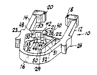
Flgur~ 2 show~ a per~pectlve view of Flgure 1.
D13 SCRIPTION OF THR PREFI~ D EMBODIIIl~NT
R~ferrlng to the drawings, there 18 shown a
on~-p~ece pla~tic towsl clamp lO compr~ lng a pair o~ arms 12 ~ :
and 14 ~o$ned by a res~l~ent hlng~ portion 16 and having a
pair of ~ac~ng ~w members 18 and ZO at the free ends o~ the
arm~. .
~ he inner ends o~ arms 12 and 14 ~re pro~ided with
mutually engageable locking mean~ 21 and 22, respect~vely, and
outar thumb and finger engaging padE~ 23 and 24, respectively.
Locking mean~ 22 includes a guiding rib 27 and a transverse
hook or tooth 26, the latter being suffioiently wide to
overlap both of the row~ of parallel toothed m2mbers a~
-- 4 --
~ -
. . : , , - , . ~ : .
~ . . .. . . . . . .

203~8
discussQd below.
Locking means 21 compriseE~ a pair o~ parallel
toothed members 30 and 32, memb~r 30 being a top row or set of
tQeth and m~mber 32 b~ing a bot~om row or ~et of te2th. A~
bQ~t 6een ~n Figure 2, ~ets 30 and 32 are spaced in parallel
planes on aither side o~ a E~eparA~ing channel 33. A~ thQ arms
are pres~ed together, guiding rib 27 w~l slide within channel
33. While t~e teeth of tooth sa~ 30 and 32 ar~ ~paced
transversQly, it w~l b~ understood that as ~he arms 12 and 14
are pressed together, locking me~ber 26 w~l engage the teeth
o~ th~ sets 30 and 32 in an al~ærnat~ng manner depending upon
the mannQr in which t~eth ara arranged. In tha preferred
s~bodimQnt, locking means 21 1~ provided w~th ~ive teeth 40,
42, 44, 46 and 48 which are arranged in alternating pairs 80
that tooth sot 30 ha~ two front taeth 40 and 42 wh~e ~ember
32 i~ provid~d with the next two, mlddl~ teet~ 44 and 46 and
menber 30 ~8 provided wlth th~ final tooth 48. The t~e~h
could b~ arrangsd ln a 8ingle, alternating patt~rn (not shown)
with tooth ~t 30 having thrse space~ singlQ te~th 40, 44 and
48 and tooth set 32 having two spaced singl~ teeth 42 and 46.
Tooth set~ 30 and 32 h~ve inner Elurface~ 50 and 51 ~acing
channel 37 and outer sur~ace~ 52 and 53 faclng aw~y fro~ the
clamp. Whichevar tooth pattern i~ cho~en to embody the
lnvention, it i8 important that the inner surfaces 50 and 51
o~ each tooth w~l alway be unobstruc~edly visible from a
point above (or bQlowj the plane o~ the clamp, as ~est 6esn in
F~gur~ 1. The teeth 40-48 are uni~or~ly spaced along locking
- 5 -
.. ..
.: . - ~ . . . ~ .: ,
. . . .

203~49~
means 21 (i.e. within the plane o~ the cla~np) 50 ~ UBer Wlll
not sense the gap between the teQth but w~ll m~r~ly feel a
uniform ratcheting action as arms 12 and 14 are pressed
together and tooth 26 latches one tooth after another. It ic
noted th~ tooth 26 1R wide enough to engage teeth on either
sQt 30 or 32, and in ths pref~rred Qmbodl~nt the outer
~ur~ace~ o~ tooth 26 ar~ parallel to out~r 3urface~ 52 and
53.
In order to enable the operation of guiding rib 27
throughout the range of motion o~ arm~ 12 and 14, it i8
neces~ary that the rlb be lon~r than the length o~ the gap
betwe~n any two con6ecutiv~ tseth on either set 30 or 32.
Obviously, i~ thr~ i~ an innermost are~ on any set that i8
devoid o~ teeth (e.g. beyond tooth 48) rib 27 must bQ long
enough to prevent tooth 26 from twl~t~ng out o~ th~s area.
It will be understood by those sk~lled ln the art
that numerous improvements and modiflcation~ may b~ made to
the pre~erred embodlment of the invention disclosed herein
without departing from the spirit and scope thereof.
' : '' ~ ' .-' . ' , : . ..................... ' , -. ,: ~ ,.'
- -
- . : . .

Dessin représentatif
Une figure unique qui représente un dessin illustrant l'invention.
États administratifs

2024-08-01 : Dans le cadre de la transition vers les Brevets de nouvelle génération (BNG), la base de données sur les brevets canadiens (BDBC) contient désormais un Historique d'événement plus détaillé, qui reproduit le Journal des événements de notre nouvelle solution interne.

Veuillez noter que les événements débutant par « Inactive : » se réfèrent à des événements qui ne sont plus utilisés dans notre nouvelle solution interne.

Pour une meilleure compréhension de l'état de la demande ou brevet qui figure sur cette page, la rubrique Mise en garde , et les descriptions de Brevet , Historique d'événement , Taxes périodiques et Historique des paiements devraient être consultées.

Historique d'événement

Description Date
Inactive : CIB expirée 2016-01-01
Inactive : CIB désactivée 2011-07-26
Inactive : CIB de MCD 2010-02-01
Inactive : CIB expirée 2010-01-01
Inactive : CIB de MCD 2006-03-11
Demande non rétablie avant l'échéance 1993-10-04
Le délai pour l'annulation est expiré 1993-10-04
Réputée abandonnée - omission de répondre à un avis sur les taxes pour le maintien en état 1993-04-02
Inactive : Demande ad hoc documentée 1993-04-02
Demande publiée (accessible au public) 1991-10-14

Historique d'abandonnement

Date d'abandonnement Raison Date de rétablissement
1993-04-02
Titulaires au dossier

Les titulaires actuels et antérieures au dossier sont affichés en ordre alphabétique.

Titulaires actuels au dossier
TOMMY G. DAVIS
TOMMY G. DAVIS
Titulaires antérieures au dossier
S.O.
Les propriétaires antérieurs qui ne figurent pas dans la liste des « Propriétaires au dossier » apparaîtront dans d'autres documents au dossier.
Documents

Pour visionner les fichiers sélectionnés, entrer le code reCAPTCHA :


Pour visualiser une image, cliquer sur un lien dans la colonne description du document. Pour télécharger l'image (les images), cliquer l'une ou plusieurs cases à cocher dans la première colonne et ensuite cliquer sur le bouton "Télécharger sélection en format PDF (archive Zip)" ou le bouton "Télécharger sélection (en un fichier PDF fusionné)".

Liste des documents de brevet publiés et non publiés sur la BDBC .

Si vous avez des difficultés à accéder au contenu, veuillez communiquer avec le Centre de services à la clientèle au 1-866-997-1936, ou envoyer un courriel au Centre de service à la clientèle de l'OPIC.


Description du
Document 
Date
(aaaa-mm-jj) 
Nombre de pages   Taille de l'image (Ko) 
Abrégé 1991-10-13 1 26
Revendications 1991-10-13 2 77
Dessins 1991-10-13 1 30
Description 1991-10-13 6 226
Dessin représentatif 1999-08-19 1 11