Note : Les descriptions sont présentées dans la langue officielle dans laquelle elles ont été soumises.
-- 1 -- 8~--~324
3 ~ 3
RVLLE:R AND lB~LL BE ING BEARIMG ISOLATO:R
RELATED APPLICATIONS
This application is related to U.S. Serial
No. 509,396 titled TAPERED BEARING BEARING ISOLATOR,
assigned to the assignee of this application and filed
the same day, APRIL 16 , 1990, as this
application.
BACRGROU~D OF THE INVE~TTON
Field of the Invention
This invention rela~es to bearing isolators for
mounting roller and~or ball bearings to supporting
structures to isolate the supporting structures fxom the
primarily radial vibrations and oscillations that the
bearings, and the shafts rotatably supported thereby,
are subject to. More particularly, this invention
relates to isolators utilized in connection with roller
and/or ball bearings rotatably supporting torque
transmitting shafts in vehicular mechanical change gear
transmissions.
Resilient, flexible and~or cushioned bearing
mounts or isolators utilized to isolate a ~upport member
from the vibrations and oscillations to which a bearing
and the rotatabiy supported member, most often a shaft
of some type, is subject to are, of course, well known
in the prior art. E~amples of such prior art devices
may be seen by reference to United States Patents Nos.
2,733,1Q8; 3,309,154; 3~385,543; 3,709,570; 4,422,780
and 4,825,718, the disclosures o all of which are
hereby incorporated b~ reference.
- 2 ~
Vehicular drivetrain components such as drive
a~les and mechanical change gear transmissions which
utilize bearings, included ball and roller bearings, to
rotatably support torque transmitting memb~rs, u3ually
comprising some type of shafts, in a housing are well
known in ths prior art as may be seen by reference to
United ~tates Patents Nos. 4,788,889; 4,754,665;
4,736,643; 4,735,1~9; 4,709,590; 4,373,403; 4,761,867
and 4,678,017, the disclosures of all o which are '~
hereby incorporated by reference. J`
The use of bearing isolators and/or of
cushionedr resilient and/or flexible bearing mounts in
drivetrain components to isolate the drive train
component housing from shaft and gear vibrations and
oscillations to reduce wear, to dampen the vibrations or
oscillations, to increase vehicular occupant comfort
and/or to minimiz~ drive train noise i~ known. However,
the previous resilient bearing mounts/bearing isolators
were not totally satisfactory as the prior art devices
were complicated and/or e~pensive to manuacture and/or
assemble and/or utilized rubber and/or other nonmetallic
materials which were e~pensive, not totally elastic, of
an improper spring rate, not long weari~g, and/or
excessively sensitive to temperature and lubricants
and/or did not limit deflection and stress of the
resilient members.
SUMMARY OF THE INVENTION
In accordance with the present invention, the
drawbacks of the prior art have been minimized or
overcome by the provision of a new and improved
relatively simple, inexpensive all metallic bearing
isolator for ball and roller bearings.
The above is accomplished by providing a
bearing isolator compri~ing two principal components,
each all metallic ~preferably of a suitable steel3 and
each oE a relatively simple and ine~pensively produced
structure.
2 ~
The principal components of the isolator of khe
present invention include (i~ an annular, flanged wear
ring/retainer sleeve for receipt in the bearing support
aperturQs of the housing support walls, ~ii) a generally
tubular shaped radial wave ~pring which is resiliently
radially deformable and is resiliently rad;ally deformed
between the inner diameter of the retainer and the outer
diameter of ~he reta;ned bearing outer race and ~iii) a
bump stop which limits travel and stress of the radial
wave spring.
Preferably, the radial wave springs are made of
a spring steel, such as for example SA~ 6150 or the
like, while the retainer and wear rings are made of a
standard gear or shaft steel, such as SAE 1010, 1018 or
1020 or the like and are preferably surface hardened.
Accordingly, it is an object of the present
invention to provide a new and improved bearing isolator
which is of a relatively simple, preferably all
metallic, construction and which is suitable for use
with ball and straight roller bearingsO
This and other objects and advantages of the
present invention will become apparent from a reading o~
the detailed description of the preferred embodiment
taken in connection with the attached drawings.
_RIEF DESCRIPTION OF THE DRAWINGS
Figure 1 is a partial sectional view of a
vehicular transmission utilizin~ the bearing isolators
of the present invention.
Figure lA is a schematic illustration of a
typical change gear transmission as illustrated in
Figure 1.
Figure 2 is a sectional view of the retainer
portion of the bearing isolator of the present invention.
Figure 3 is an elevational view of a radial
wave spring member of the b~aring isolator of the
present inv~ntion.
Figure 4 is a side view, in section, of the
radial wave spring illustrated in Figure 3.
DESCRIPTI~N OF THE PREFERRED EMBODIMENT
In this disclosure, certain terminology will be
us2d for convenience and reference only and will not be
limit;ng. For e~ample, the terms ~orward" and
~rearward~ will refer to directions forward and rearward
of the transmission as normally mounted in a vehicle.
The t~rms ~rightward" and "leftward" will refer to
directions in the drawings in connection with which the
terminology is used. The terms "inwardly" and
"outwardly~ will refer to directions toward and away
from, respectively, the geometric center of the
apparatus being described. The terms "upward" and
~downward" will refer to directions taken in the
drawings in connection with which the terminology is
used. All of the foregoing terms include the normal
derivatives and e~uivalents thereof.
A typical change gear transmission or
transmission section 10 with which the bearing isolator
assembly or the present invention may be advantageous
utilized may be seen by reference to Figures 1 and lA.
Transmission 10 is a simple transmission, or
transmission section, of the twin countershaft type
which is well known in the prior art and which may be
understood in greater detail by reference to U.S. Patent
~os. 3,105,395; 3,611,823; 4,15~,94~; 4,445,393 and
4,194,410, the disclosures of all of which are hereby
incorporated by reerence.
The illustrated transmission 10 comprises an
;nput shaft 14 carrying an input gear 16 for rotation
2 ~ ~ ~ f,~ rJ ~
therewith. The input shaft 14 i~ intended to be d~iven
by a prime mover (not shown) through a master clutch or
torque converter (not shown) as is well known in the
art. A pair of substantially identical countershats 18
and 18A are rotatably mounted in the housing by means o~
straight roller bearings 20 an~ 20A~ A main or output
shaft 22 is provided which is preferably floatingly
and/or pivotably mounted in the transmission housing H.
Each of the countershafts 1~ and l~A carry
countershaft gears 24, 26, 28, 30 and 32 fi~ed thereto
for rotation therewith. Countershaft gear 24 is
constantly ~eshed with the input gear 16. Third speed
main shaft gear 34 surrounds main shaft 22 and is
constantly meshed with and supported by the countershaft
gears 26. Second speed mainshaft gear 36 surrounds
mainshaft 22 and is constantly meshed with and supported
by countershaft gear 28. First speed mainshaEt gear 38
surrounds mainshaft 22 and is constantly meshed and
~upported by the countershaft gears 30. The reverse
mainshaft gear 40 surrounds mainshaft 22, and is
constantly meshed with and supported by 3 pair of idler
gears (not shown) which, in turn, are constantly meshed
with and driven by the countershaft gears 32.
Preferably, as is well known in the art, mainshaft gears
34, 36, 38 an~ 40 are radially movable relative to
mainshaft 22. The advantages of utilizing a floating
mainshaft 22 and/or floating mainshaft gears are well
known in the art and may be appr~ciated in greater
detail by the aforementioned U.S. Patent ~o. 3,105,395.
A~ially slidable jaw clutches 42, 44 and 46 are
mounted, preferably by a splined connection, to
mainshaft 22 for a~ial sliding movement relative
thereto, and for rotatio~ therawith. Clutch 42 may be
moved to the left from the neutral position shown to
2 ~ 9 ~
selectably couple the mainshaft Z2 directly to the input
qear 16 and input shaft 14 for fourth or direct drive of
transmission 10, or moved rightwardly from the pasition
shown to engage mainshaft gear 34 with mainshaft 22 or
third spsed operation of transmission 10. Clutch 44 may
be moved from the position shown leftwardly to engage
mainshaft gear 36 with mainshaft 22 for second speed
operation or may be moved rightwardly from the position
shown to engage mainshaft gear 38 with mainshaft 22 for
first speed operation of transmission 10. Clutch 46 may
be moved rightwardly from the neutral position shown to
engage mainshaft gear 40 with mainshaf~ 22 for reverse
operation of transmission 10. Of course, clutches 42,
44 and 46 may be positive clutches, friction clutches,
lock clutches and/or synchronized clutches. A shift
fork or yoke 48 is received in a groove in clutch 42 for
controlling the axial position of clutch 42 relative to
mainshaft 22.
A shift fork ~0 is received in a groove in
clutch 44 for a~ially controlling the position of clutch
44 relative to mainshaft 22. A shift fork 52 is
received in an axial groove in clutch 46 for controlling
the a~ial position of clutch 96 relative to mainshaft
22. As is known, the axial positioniny of the shift
forks is controlled by a shift bar housing assembly or
the like.
As indicated above, countershaft 18 and the
gears rotatably secured thereto are substantially
identical to countershaft 18A and the gears rotatably
associated therewith. Accordingly, only the rotational
support of the a~ially reax end of countershaft 18 in
housing H will be described in detail herein with the
understanding that the rotational support of the forward
end Qf countershaft 18 and of countershaft 18A is
~ubstantially structurally and functional identical
thereto.
- 7 ~ 9~Jf.)'~
~s may he sean in greater detail by reference
to Figure 1, the a~ially rear end o~ countersha~ 18 is
rotatably supported in housing ~ by means o~ straight
roller bearing 20, which, with the possible e~ception of
a size difference, is substantially functionally and
s~ructurally identical with ~he forward roller bearings
and of a well known prior art construction.
Briefly, each of the roller bearings includes
an inner race 54 adapted to be snugly received on a
reduced diameter portion 56 of the countershaft 18, an
outer race 58 adspte~ to be snugly received within a
bore 60 of the support housing H and a plurality of
rollers 62 each rotatable about an a~is substantially
parallel to the common a~is 64 of the shaft 18 and the
inner and outer racss of the bearing. The outer bearing
race defines an outer diameter surface 59 directly or
indirectly mounted in bore or aperture 60 and also
defines an a~ially outwardly facing surface 61. In a
typical installation, countershaft 18 will include an
a~ially outwardly facing shoulder 65 which will
cooperate with an a~ially inwardly faclng surface 66
provided on the inner race 54 of the bearing, in
combination with ~nap ring 67 rec~ived on the outer end
of shaft 18, to 2~ially position the shaft relative to
~earing 20.
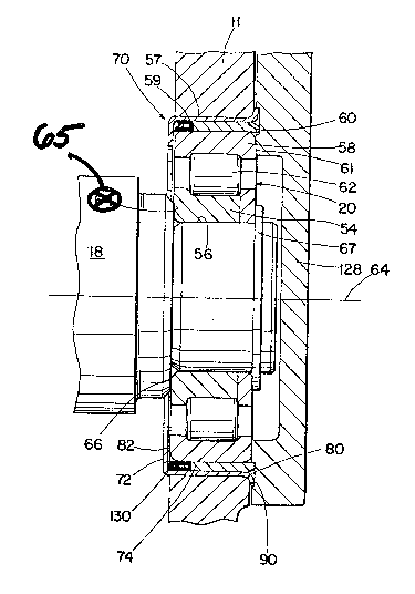
The bearing isolator assembly 7Q of the present
invention is comprised of three main components, namely
a retainer member 72, a radial wave spring member 74 and
a bump stop member 130.
Preferably, for purposes of simplicity of
m~chining, minimization of material costs and improved
resistance to wear and temperature and lubricant damage,
-- 8 --
~ 3~
preferably the retainer 72 and the wear ring are made of
a æuitable surface hardened s~eel material, such as SAE
lOlB-10~9 steel, ~or e~ample, while the radial waqe
spring 74 is of a suitable spring steel such a~, for
e~ample, SAE 6150 steel.
As may be seen in greater detail ~y reference
to Figure 2, the retainer 72 is of a generally tubular
shape having a radially outwardly extending flange 80 at
one a~ial end thereof and a radially inwardly extending
$1ange 82 at the opposite a~ial end thereof. The
generally tubular intermediate portion 84 o~ the
retaining member has an outer diameter 86 generally
equal to the inner diameter of the bearing receiving
aperture 60 provided in the housing and is axially
retained in the housing by means of flange 80
interacting with a shoulder 90 provided in the housing.
A radial wave spring 74, see Figure 3 and
Figure 4, is telescopically received within the tubular
body portion 84 of the retainer member and defines a
major or ma~imum outer diameter 92 which is slightly
less than or equal to the inner diameter 94 of the
tubular portion 84 of the retaining member 72. The
radial wave spring 74 also defines a minor or minimum
inner ~iameter 96 which is greater than the inner
diameter 98 defined by inwardly extending flange portion
a2 of the retainer 72. The radial wave spring 74 is
designed to be received in a press fit relationship on
the outer diameter of the outer bearing race 5B of the
bearings ~0 as may be seen by reference to Figure 1.
Further, the inner diameter 98 defined by the inwardly
e~tending flange 82 of the retainer is less than the
outer diameter 92 of the radial wave spring and thus the
radial wave spring is a~ially retained relative to the
housing H by the retaining member 72. The diameter 98
of flange 82 is less than the outer diameter of the
outer bearing race 5B so the bearing is retained axially
by the retaining member 72~
- 9 ~ 3 p~ r~ 3
Re~erring specifically to Figures 3 and 4, it
may be seen, that ~he radial wave spring mernber 74 is a
generally ~ubular member with a substantially constant
cross sectional radial wall thickness 100. The radial
outer diameter varies from a major or ma~imum value 92
to a minor or minimum value 102, and the radial inner
diameter Yaries from a minor or minimum value 96 to a
major or maximum value 10~, in a substantially periodic
smoothly and continuous manner with the ma~imums and
minimums occurring at at least three generally equally
spaced circumferentially space~ locations. As the
radial wave spring is of a spring steel, it is
substantially resilientl~ deformable with no plastic
deformation to allow a predetermined amount of resilient
radial ~ovement of the rotational a~is 64 of the
bearings 20 and the shaft 18 rotatably supported
thereby.
As the radial wall thickness lOQ of the radial
wave spring is substantially constant, the major outer
and inner diameters, and the minor outar and inner
diameters, will occur at the same circumferential
position about the generally tubular radial wave
spring. Preferably, the difference in magnitude between
the major and minor outer diameters, and between the
major and minor inner diameters, will be in the range of
0.1% to 50.0% of the mean values thereof.
At the rearward or rightward end of the
transmission 10, a b~aring cover member 128 interacts
with housing H to retain the bearing isolator assembly
2 ~
70 and bearing 20 in the housing ~. A stsel ring 130
may be used to provide positive radial stop or, bearing
20. Ring 130 is axially interposed the inwardly
e~tending flange 82 of retainer 72 and the radial wave
spring 740
Preferably, the radial spring rate of the wave
spring is in range of 10.0% to 150.0% of the radial
spring rate of bearing 20.
Accordingly, it may be seen, tha~ a relatively
simple and ine~pensive bearing isolator assembly,
preferably comprised of all steel components, and which
will dampen and/or isolate radial vibra~ions and is thus
suitable for use with straight roller and ball
bearings, has been provided.
While there has been described what at present
is considered to be the preferred embodiment of thls
invention, it will be obvious to those skilled in the
art that various changes and modifications may be made
therein without departing from the spirit and the scope
of the invention as hereinafter claimed.