Sélection de la langue

Search

Sommaire du brevet 2040528 

Énoncé de désistement de responsabilité concernant l'information provenant de tiers

Une partie des informations de ce site Web a été fournie par des sources externes. Le gouvernement du Canada n'assume aucune responsabilité concernant la précision, l'actualité ou la fiabilité des informations fournies par les sources externes. Les utilisateurs qui désirent employer cette information devraient consulter directement la source des informations. Le contenu fourni par les sources externes n'est pas assujetti aux exigences sur les langues officielles, la protection des renseignements personnels et l'accessibilité.

Disponibilité de l'Abrégé et des Revendications

L'apparition de différences dans le texte et l'image des Revendications et de l'Abrégé dépend du moment auquel le document est publié. Les textes des Revendications et de l'Abrégé sont affichés :

  • lorsque la demande peut être examinée par le public;
  • lorsque le brevet est émis (délivrance).
(12) Demande de brevet: (11) CA 2040528
(54) Titre français: DISPOSITIF DE REGLAGE DE LA POSITION DU SIEGE ET DU DOSSIER D'UNE CHAISE
(54) Titre anglais: CHAIR BACK AND SEAT ADJUSTMENT
Statut: Réputée abandonnée et au-delà du délai pour le rétablissement - en attente de la réponse à l’avis de communication rejetée
Données bibliographiques
(51) Classification internationale des brevets (CIB):
  • A47C 03/20 (2006.01)
  • A47C 01/027 (2006.01)
(72) Inventeurs :
  • DEGELDER, JACOB (Etats-Unis d'Amérique)
  • DEGELDER, JACOB (Etats-Unis d'Amérique)
(73) Titulaires :
  • VOGEL PETERSON COMPANY
(71) Demandeurs :
  • VOGEL PETERSON COMPANY (Etats-Unis d'Amérique)
(74) Agent: OSLER, HOSKIN & HARCOURT LLP
(74) Co-agent:
(45) Délivré:
(22) Date de dépôt: 1991-04-16
(41) Mise à la disponibilité du public: 1991-11-04
Licence disponible: S.O.
Cédé au domaine public: S.O.
(25) Langue des documents déposés: Anglais

Traité de coopération en matière de brevets (PCT): Non

(30) Données de priorité de la demande:
Numéro de la demande Pays / territoire Date
07/518,378 (Etats-Unis d'Amérique) 1990-05-03

Abrégés

Abrégé anglais


ABSTRACT
A chair having a seat and back adjustment
mechanism in which a single handle is operable to hold or
release both the seat and the back at selected independent
angles. A bank of plates serving the seat and a bank of
plates serving the back are interleaved and positioned to
be compressed by the handle.

Revendications

Note : Les revendications sont présentées dans la langue officielle dans laquelle elles ont été soumises.


-5-
The embodiments of the invention in which an exclusive
property or privilege is claimed are defined as follows:
1. A chair adjustment mechanism for use with a
chair having a seat, a back and a pedestal comprising
a) an elongated frame mounted on the
pedestal in a manner to hold such frame
in a substantially horizontal plane;
b) a seat support piece pivotally mounted
about a first horizontal pivot pin on
the frame;
c) a back bracket mounted about a second
horizontal pivot pin on the seat
support piece;
d) a first set of friction plates having
slots therein mounted to the second
pivot;
e) a second set of friction plates having
slots therein mounted to a third
horizontal pivot pin on the back
bracket; and
f) a horizontal adjustment handle mounted
through the frame and the slots of such
sets of plates such adjustment handle
rotatable to compress the plates
together in lock position
whereby the seat and back are held in selected orientations
with the horizontal frame.
2. The chair mechanism of claim 1 in which back
height is adjustable.
3. The chair mechanism of claim 1 in which the
seat support piece is held to the seat utilizing cross
piece plates which interlock therewith.

Description

Note : Les descriptions sont présentées dans la langue officielle dans laquelle elles ont été soumises.

2 ~ 2 8
CHAIR BACK AND SEAT ADJUSTMENT MECHANISM
Background of the I~vention
Chair back adjustment devices using a series of
engaging plates and a clamp are old (U.S. Patent No.
4,062,587) and chair seat adjustments using a threaded stem
have also ~een proposed (V.S. Patent No. 3,712,672).
SummarY Of The Invention
Broadly, the present invention comprises a chair
10 adjustment mechanism having an elongated horizontal
pedestal supported frame which frame remains in its
horizontal position during chair operation. Pivotally
mounted on the frame is a chair seat support and also
pivotally mounted on the frame is a back bracket for
supporting a back rest. A set of slotted plates are
mounted on the frame and a second set on the back bracket.
The tilt of the back and seat is controlled by a locking
I stem passing through the slots of both sets of plates.
It is a feature of the invention that both seat
and back tilts can be selected by the chair operators and
such positions maintained by operating a single control
handle.
25 Brief Description Of The Drawings
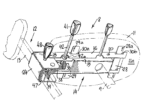
Fig. l is a perspective view of the chair
adjustment mechanism seen from the bottom;
Fig. 2 is a partial side elevational view of the
mechanism;

--2--
~0 ~28
Fig. 3 is a bottom view of the mechanism;
Fig. 4 is a partial top view of ~he mechanism
seat support housing and its seat mount cross plates.
Description Of The Preferred Embodiment
In the drawings, chair 8 with pedestal 9
(partially) shown includes oval seat 11 with seat bottom
lla, back 12, back support post 13 and seat and back
adjustment mechanism 14.
Adjustment mechanism 14 includes pedestal
horizontal frame piece 15 which remains in a substantially
horizontal position throughout operation of chair 8.
Pivotal seat support housing 16 which pivots about pin 20
mounted in frame piece 15 with seat-bottom-engagement piece
17 and spaced-apart vertical pieces 19 (at the right side
as viewed by the person sitting in chair 8) and piece 21 on
the left side. Pieces 17, 19 and 21 form a U-shape in
cross-section and preferably are integrally formed.
Frame piece 15 supports a back bracket 24 pivotal
about pin 18. Pedestal post 9 is raised by operation of
control handle 26 employing a hydraulic arrangement (not
shown). Seat support housing 16 is secured to seat bottom
lla of seat 11 with forward cross mount plate 28 and
rearward cross mount plate 29. Notches 31 in plates 28, 29
interlock with indentations 17a in seat-bottom-engagement
piece 17 (see Fig. 4).
Also pivotal about pin 18 of seat support housing
16, is a bank or set of seat friction plates 3Ç. A second
set of back friction plates 38 are mounted on pin 39 of
back bracket 24. Both sets of friction plates 36, 38 have
35 slots 36a, 38a. The sets of friction plates 36, 38 are

2 ~ 2 ~
interleaved and are compressed by ad~ustment control handle
41 having threaded stem 42. Stem 42 carries limit ring
42a. Handle 41 is mounted parallel to pins 18 and 39 and
carries a threaded portion to permit urging the sets of
plates 36, 38 together in lock posi~ion or releasing the
plates for adjustment.
Turnin~ to ~igs. 2, 3 and 4, spring 43 urges back
bracket 24 to a position in which back friction plates 38
move left in Fig. 2 until the end of slot 38a engages stem
10 42. In that position, back post 13 is angled from the
vertical position toward a person sitting in the chair.
Fig. 2 shows the back post 13 urged against spring 43 to
the vertical position. 5tem 42 of handle 41 carries
washers 44a, 44b, and collar 46 and stem nut 42b along with
both sets of friction plates 36, 38. The washers 44a, 44b,
collar 46, and plates 36, 38 are confined between fralne
sides 15a, 15b for tightening and relaxation (Fig. 3). The
tightening of plates 36, 38 is accomplished by turning
handle 41 which turns stem 42, which through its threaded
20 end causes threaded nut 42b held against turning in a
recess in vertical piece 19, to translate along stem 42
toward handle 41. As nut 42b moves in this direction it
urges collar 46 against plates 36, 3~ which plates are
confined by washers 44a, 44b. Relaxation o~ plates 36, 38
i5 accomplished by turning stem 42 in the opposite
direction.
Back post 13 is adjustable up or down as housed
in oval plastic grip piece 47. Grip piece 47 has a wedge
section 51 attached, which complements the angle of metal
wedge piece 52 which slides back and forth on stem 49.
Depending on the way knob 48 on stem 49 is rotated, it will
increase or decrease pressure against back post 13
35 positioned in piece 47 so that back assembly 12 is locked

_4_ 2~
in place or released at will. Back assembly 12 with post
13 moves up or down for adjustment of back to correct
height~ Threaded stem 49 carries back adjustment handle
48.
Turning to Figs. 3 and 4, cross plates 28, 29 are
slidable for assembly purposes through rectangular seat
support openings 30a, 30b in each side of the sides 19, 21
of chair support housing 16. Plates 28, 29 are inserted
until their notches 31 match seat support notches 17a
10 permitting plates 2~, 29 to be moved upwardly until
indentations 17a and notches 31 interlock (Fig. 4). In
this position, cross plates 28, 29 are below but touching
the underside of piece 17. In this position, plates 23, 24
are screwed, bolted or otherwise secured to seat bottom
lla. Piece 17, as held against seat bottom by fasteners
through holes 28a, 29a, cannot move in any direction.
To accomplish dual adjustment of seat and back
(or if only one adjustment is desired), adjustment handle
20 41 is turned to release the banks of friction plates 36, 38
and permit the seat housing 16 and back bracket 24 to be
moved to any angular position vis-a-vis frame 15 consistent
with the length o the slots 36, 38 and cross-sectional
size of stem 42 therein. ~s the plates move about their
25 pivots control handle 41, mounted in frame 1~, remains in
the slots 36a, 38a. once the seat 11 and back 12 are at
the desired angles, control handle 41 including its stem 42
is turned to tighten the plates 36, 38 together until they
are tight enough that normal chair use will not exert
forces which permit sliding movement between or among the
plates 36, 38. The height of back post 13 is then,
optionally, also adjustable as described above.

Dessin représentatif
Une figure unique qui représente un dessin illustrant l'invention.
États administratifs

2024-08-01 : Dans le cadre de la transition vers les Brevets de nouvelle génération (BNG), la base de données sur les brevets canadiens (BDBC) contient désormais un Historique d'événement plus détaillé, qui reproduit le Journal des événements de notre nouvelle solution interne.

Veuillez noter que les événements débutant par « Inactive : » se réfèrent à des événements qui ne sont plus utilisés dans notre nouvelle solution interne.

Pour une meilleure compréhension de l'état de la demande ou brevet qui figure sur cette page, la rubrique Mise en garde , et les descriptions de Brevet , Historique d'événement , Taxes périodiques et Historique des paiements devraient être consultées.

Historique d'événement

Description Date
Inactive : CIB de MCD 2006-03-11
Le délai pour l'annulation est expiré 1994-10-17
Demande non rétablie avant l'échéance 1994-10-17
Réputée abandonnée - omission de répondre à un avis sur les taxes pour le maintien en état 1994-04-18
Inactive : Demande ad hoc documentée 1994-04-18
Demande publiée (accessible au public) 1991-11-04

Historique d'abandonnement

Date d'abandonnement Raison Date de rétablissement
1994-04-18
Titulaires au dossier

Les titulaires actuels et antérieures au dossier sont affichés en ordre alphabétique.

Titulaires actuels au dossier
VOGEL PETERSON COMPANY
Titulaires antérieures au dossier
JACOB DEGELDER
Les propriétaires antérieurs qui ne figurent pas dans la liste des « Propriétaires au dossier » apparaîtront dans d'autres documents au dossier.
Documents

Pour visionner les fichiers sélectionnés, entrer le code reCAPTCHA :


Pour visualiser une image, cliquer sur un lien dans la colonne description du document. Pour télécharger l'image (les images), cliquer l'une ou plusieurs cases à cocher dans la première colonne et ensuite cliquer sur le bouton "Télécharger sélection en format PDF (archive Zip)" ou le bouton "Télécharger sélection (en un fichier PDF fusionné)".

Liste des documents de brevet publiés et non publiés sur la BDBC .

Si vous avez des difficultés à accéder au contenu, veuillez communiquer avec le Centre de services à la clientèle au 1-866-997-1936, ou envoyer un courriel au Centre de service à la clientèle de l'OPIC.


Description du
Document 
Date
(aaaa-mm-jj) 
Nombre de pages   Taille de l'image (Ko) 
Abrégé 1991-11-03 1 8
Dessins 1991-11-03 2 54
Revendications 1991-11-03 1 28
Description 1991-11-03 4 141
Dessin représentatif 1999-07-13 1 19
Taxes 1993-03-22 1 25