Note : Les descriptions sont présentées dans la langue officielle dans laquelle elles ont été soumises.
20518g7
' -
SH EET TRANSPORT SYSTEM WITH IMPROVED REGISTRATION
This invention relates generally to an electrophotographic
printing machine, and more particularly concerns a sheet transport for
moving a sheet in a path to enable a toner image to be transferred thereto.
The invention also particularly concerns a sheet transport for moving a
sheet in a recirculating path to enable successive toner powder images to
be transferred thereto in superimposed registration with one another.
The marking engine of an electronic reprographic printing
system is frequently an electrophotographic printing machine. In an
electrophotographic printing machine, a photoconductive member is
charged to a substantially uniform potential to sensitize the surface
thereof. The charged portion of the photoconductive member is thereafter
selectively exposed. Exposure of the charged photoconductive member
dissipates the charge thereon in the irradiated areas. This records an
electrostatic latent image on the photoconductive member corresponding
to the informational areas contained within the original document being
reproduced. After the electrostatic latent image is recorded on the
photoconductive member, the latent image is developed by bringing toner
into contact therewith. This forms a toner image on the photoconductive
member which is subsequently transferred to a copy sheet. The copy sheet
is heated to permanently affix the toner image thereto in image
configuration.
Multi-color electrophotographic printing is substantially
identical to the foregoing process of black and white printing. However,
rather than forming a single latent image on the photoconductive surface,
successive latent images corresponding to different colors are recorded
thereon. Each single color electrostatic latent image is developed with
toner of a color complementary thereto. This process is repeated a plurality
of cycles for differently colored images and their respective
complementarily colored toner. Each single color toner image is
transferred to the copy sheet in superimposed registration with the prior
toner image. This creates a multi-layered toner image on the copy sheet.
20~ 1897
.,.,_
Thereafter, the multi-layered toner image is permanently affixed to the
copy sheet creating a color copy. The developer material may be a liquid or
a powder material.
In the process of black and white printing, the copy sheet is
advanced from an input tray to a path internal the electrophotographic
printing machine where a toner image is transferred thereto and then to an
output catch tray for subsequent removal therefrom by the machine
operator. In the process of multi-color printing, the copy sheet moves from
an input tray through a recirculating path internal the printing machine
where a plurality of toner images is transferred thereto and then to an
output catch tray for subsequent removal. With regard to multi-color
printing, a sheet gripper secured to a transport receives the copy sheet and
transports it in a recirculating path enabling the plurality of different color
images to be transferred thereto. The sheet gripper grips one edge of the
copy sheet and moves the sheet in a recirculating path so that accurate
multi-pass color registration is achieved. In this way, magenta, cyan,
yellow, and black toner images are transferred to the copy sheet in
registration with one another.
Some systems which have been designed for transporting a copy
sheet into registration with a toner image developed on a moving member
accelerate the copy sheet during transfer of the toner image from the
moving member to the copy sheet. Such acceleration may occur when the
leading portion of the sheet is being negotiated through a nonlinear path
while at the same time the trailing portion of the copy sheet is traveling
through the transfer zone. The above acceleration may cause a
deterioration of the integrity of the image produced on the copy sheet due
to slip between the copy sheet and the moving member while the sheet is
traveling through the transfer zone. An example of the above
deterioration is a blurred or smeared image produced on the copy sheet.
The following disclosures may be relevant to various aspects of
the present invention:
2~189~
, _
US-A-4,118,025
Patentee: Konars et al.
Issued: October3,1978
US-A-4,441,390
Patentee: Hechler et al.
Issued: April 10,1984
US-A-4,697,512
Patentee: Simeth
Issued: October6,1987
US-A-4,849,795
Patentee: Spehrley, Jr. et al.
Issued: July 18,1989
US-A-4,905,052
Patentee: Cassano et al.
Issued: February27,1990
The relevant portions of the foregoing disclosures may be briefly
summarized as follows:
US-A-4,118,025 discloses a document conveying apparatus
having a plurality of equally spaced gripping members. As the document is
fed to the apparatus, the leading edge of the document is gripped between
two gripping members and thereafter transported to a desired location.
US-A-4,441,390 describes a sheet separating and transport
apparatus in which tear-off rollers gently grip sheets. A pair of belts are
provided which are positionable so as to grip the leading edge of a sheet as
it is being fed by a conveyor belt.
US-A-4,697,512 discloses a sheet gripper system having regular
sheet grippers with additional sheet grippers provided in spaces between
the regular grippers. The additional grippers are provided so that the front
20~18~7
edge of the sheet is held by approximately twice the number of grippers
before it enters the printing area, thereby reducing the tensile stress on the
sheet as it passes through the printing zone by at least approximately half.
US-A-4,849,795 describes an apparatus for moving a sheet in a
recirculating path by spaced belts having a sheet gripper. The leading edge
of the sheet is received by the gripper securing the sheet thereto for
movement in a recirculating path. The belts move the sheet into contact
with a photoconductive member in a transfer zone in synchronism with a
toner image developed thereon.
US-A-4,905,052 discloses a sheet transport velocity mismatch
apparatus. A plate, interposed between adjacent sheet transports,
supports the sheet until the leading edge thereof advances from the first
sheet transport to the second sheet transport. When the leading edge of
the sheet is received by the second sheet transport, the plate pivots away
from the sheet to a location remote therefrom. Since the first sheet
transport advances the sheet at a greater velocity than the second sheet
transport, the sheet forms a buckle to compensate for velocity mismatch
between the sheet transports.
In accordance with one aspect of the present invention, there is
provided an apparatus for advancing a sheet through a transfer zone and
into registration with information developed on a moving member. The
apparatus comprises means for advancing the sheet through the transfer
zone. The apparatus further comprises means, acting in unison with the
advancing means, for eliminating relative velocity between the moving
member and any portion of the sheet in the transfer zone so as to
substantially eliminate slip between the sheet and the moving member in
the transfer zone.
Pursuant to another aspect of the present invention, there is
provided a printing machine of the type having a toner image developed
on a moving member with a sheet being advanced through a transfer zone
and into registration with the toner image. The printing machine
comprises means for advancing the sheet through the transfer zone. The
printing machine further comprises means, acting in unison with the
2051897
,.,=,
advancing means, for eliminating relative velocity between the moving
member and any portion of the sheet in the transfer zone so as to
substantially eliminate slip between the sheet and the moving member in
the transfer zone.
Other features of the present invention will become apparent as
the following description proceeds and upon reference to the drawings, in
wh ich:
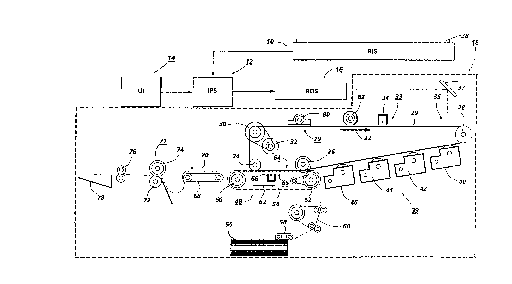
Figure 1 is a schematic elevational view illustrating an
electrophotographic printing machine incorporating the features of the
present invention therein;
Figure 2 is a schematic elevational view showing further details
of the sheet transport system used in the electrophotographic printing
machine of Figure 1 and also showing the sheet gripper of the sheet
transport system at a position prior to entering the transfer zone;
Figure 3 is a schematic elevational view showing further details
of the sheet transport system used in the electrophotographic printing
machine of Figure 1 and also showing the sheet gripper of the sheet
transport system at a position within the transfer zone;
Figure 4 is a schematic elevational view showing further detai!s
of the sheet transport system used in the electrophotographic printing
machine of Figure 1 and also showing the sheet gripper of the sheet
transport system at a position after exiting the transfer zone;
Figure 5 is a schematic planar view showing the sheet gripper of
the sheet transport system used in the electrophotographic printing
machine of Figure 1;
Figure 6 is a sectional elevational view taken in the direction of
arrows 6-6 in Figure 5; and
Figure 7 is a schematic elevational view showing the sheet
gripper of the sheet transport system used in the electrophotographic
printing machine of Figure 1.
While the present invention will hereinafter be described in
connection with a preferred embodiment, it will be understood that it is
not intended to limit the invention to that embodiment. On the contrary, it
2051897
~ ,~
is intended to cover all alternatives, modifications and equivalents as may
be included within the spirit and scope of the invention as defined by the
appended claims.
For a general understanding of the features of the present
invention, reference is made to the drawings. In the drawings, like
references have been used throughout to designate identical elements.
Figure 1 is a schematic elevational view of an illustrative
electrophotographic machine incorporating the features of the present
invention therein. It will become evident from the following discussion
that the present invention is equally well suited for use in a wide variety of
printing systems, and is not necessarily limited in its application to the
particular system shown herein.
Turning initially to Figure 1, during operation of the printing
system, a multi-color original document 38 is positioned on a raster input
scanner (RIS), indicated generally by the reference numeral 10. The RIS
contains document illumination lamps, optics, a mechanical scanning drive,
and a charge coupled device (CCD array). The RIS captures the entire
original document and converts it to a series of raster scan lines and
measures a set of primary color densities, i.e. red, green and blue densities,
at each point of the original document. This information is transmitted to
an image processing system (IPS), indicated generally by the reference
numeral 12. IPS 12 contains control electronicswhich prepare and manage
the image data flow to a raster output scanner (ROS), indicated generally
by the reference numeral 16. A user interface (Ul), indicated generally by
the reference numeral 14, is in communication with IPS 12. Ul 14 enables an
operator to control the various operator adjustable functions. The output
signal from Ul 14 is transmitted to IPS 12. A signal corresponding to the
desired image is transmitted from IPS 12 to ROS 16, which creates the
output copy image. ROS 16 lays out the image in a series of horizontal scan
lines with each line having a specified number of pixels per inch. ROS 16
includes a laser having a rotating polygon mirror block associated
therewith. ROS 16 exposes a charged photoconductive belt 20 of a printer
or marking engine, indicated generally by the reference numeral 18, to
2~51897
.~,=,
achieve a set of subtractive primary latent images. The latent images are
developed with cyan, magenta, and yeilow developer material,
respectively. These developed images are transferred to a copy sheet in
superimposed registration with one anotherto form a multi-colored image
on the copy sheet. This multi-colored image is then fused to the copy sheet
forming a color copy.
With continued reference to Figure 1, printer or marking engine
18 is an electrophotographic printing machine. Photoconductive belt 20 of
marking engine 18 is preferably made from a polychromatic
photoconductive material. The photoconductive belt moves in the
direction of arrow 22 to advance successive portions of the
photoconductive surface sequentially through the various processing
stations disposed about the path of movement thereof. Photoconductive
belt 20 is entrained about transfer rollers 24 and 26, tensioning roller 28,
and drive roller 30. Drive roller 30 is rotated by a motor 32 coupled thereto
by suitable means such as a belt drive. As roller 30 rotates, it advances belt
20 in the direction of arrow 22.
Initially, a portion of photoconductive belt 20 passes through a
charging station, indicated generally by the reference numeral 33. At
charging station 33, a corona generating device 34 charges
photoconductive belt 20 to a relatively high, substantially uniform
electrostatic potential.
Next, the charged photoconductive surface is rotated to an
exposure station, indicated generally by the reference numeral 35.
Exposure station 35 receives a modulated light beam corresponding to
information derived by RIS 10 having a multi-colored original document 38
positioned thereat. RIS 10 captures the entire image from the original
document 38 and converts it to a series of raster scan lines which are
transmitted as electrical signals to IPS 12. The electrical signals from RIS 10
correspond to the red, green and blue densities at each point in the original
document. IPS 12 converts the set of red, green and blue density signals, i.e.
the set of signals corresponding to the primary color densities of original
document 38, to a set of colorimetric coordinates. The operator actuates
20~1897
.~".
the appropriate keys of Ul 14 to adjust the parameters of the copy. Ul 14
may be a touch screen, or any other suitable controi panel, providing an
operator interface with the system. The output signals from Ul 14 are
transmitted to IPS 12. The IPS then transmits signals corresponding to the
desired image to ROS 16. ROS 16 includes a laser with rotating polygon
mirror blocks. Preferably, a nine facet polygon is used. ROS 16 illuminates,
via mirror 37, the charged portion of photoconductive belt 20 at a rate of
about 400 pixels per inch. The ROS will expose the photoconductive belt to
record three latent images. One latent image is adapted to be developed
with cyan developer material. Another latent image is adapted to be
developed with magenta developer material and the third latent image is
adapted to be developed with yellow developer material. The latent
images formed by ROS 16 on the photoconductive belt correspond to the
signalstransmitted from IPS 12.
After the electrostatic latent images have been recorded on
photoconductive belt 20, the belt advances such latent images to a
development station, indicated generally by the reference numeral 39. The
development station includes four individual developer units indicated by
reference numerals 40, 42, 44 and 46. The developer units are of a type
generally referred to in the art as "magnetic brush development units."
Typically, a magnetic brush development system employs a magnetizable
developer material including magnetic carrier granules having toner
particles adhering triboelectrically thereto. The developer material is
continually brought through a directional flux field to form a brush of
developer material. The developer material is constantly moving so as to
continually provide the brush with fresh developer material. Development
is achieved by bringing the brush of developer material into contact with
the photoconductive surface. Developer units 40, 42, and 44, respectively,
apply toner particles of a specific color which corresponds to the
compliment of the specific color separated electrostatic latent image
recorded on the photoconductive surface. The color of each of the toner
particles is adapted to absorb light within a preselected spectral region of
the electromagnetic wave spectrum. For example, an electrostatic latent
2051~97
,;""~
image formed by discharging the portions of charge on the
photoconductive belt corresponding to the green regions of the original
document will record the red and blue portions as areas of relatively high
charge density on photoconductive belt 20, while the green areas will be
reduced to a voltage level ineffective for development. The charged areas
are then made visible by having developer unit 40 apply green absorbing
(magenta) toner particles onto the electrostatic latent image recorded on
photoconductive belt 20. Similarly, a blue separation is developed by
developer unit 42 with blue absorbing (yellow) toner particles, while the
red separation is developed by developer unit 44 with red absorbing (cyan)
toner particles. Developer unit 46 contains black toner particles and may be
used to develop the electrostatic latent image formed from a black and
white original document. Each of the developer units is moved into and
out of an operative position. In the operative position, the magnetic brush
is closely adjacent the photoconductive belt, while in the non-operative
position, the magnetic brush is spaced therefrom. In Figure 1, developer
unit 40 is shown in the operative position with developer units 42,44 and
46 being in the non-operative position. During development of each
electrostatic latent image, only one developer unit is in the operative
position, the remaining developer units are in the non-operative position.
This insures that each electrostatic latent image is developed with toner
particles of the appropriate color without commingling.
After development, the toner image is moved to a transfer
station, indicated generally by the reference numeral 65. Transfer station
65 includes a transfer zone, generally indicated by reference numeral 64. In
transfer zone 64, the toner image is transferred to a sheet of support
material, such as plain paper amongst others. At transfer station 65, a sheet
transport apparatus, indicated generally by the reference numeral 48,
moves the sheet into contact with photoconductive belt 20. Sheet
transport 48 has a pair of spaced belts 54 entrained about a pair of
substantially cylindrical rollers 50 and 52. A sheet gripper, generally
indicated by the reference numeral 84 (see Figures 2-7), extends between
belts 54 and moves in unison therewith. A sheet 25 iS advanced from a
2 0 ~ 7
- .~
stack of sheets 56 disposed on a tray. A friction retard feeder 58 advances
the uppermost sheet from stack 56 onto a pre-transfer transport 60.
Transport 60 advances sheet 25 to sheet transport 48. Sheet 25 is advanced
by transport 60 in synchronism with the movement of sheet gripper 84. In
this way, the leading edge of sheet 25 arrives at a preselected position, i.e. aloading zone, to be received by the open sheet gripper. The sheet gripper
then closes securing sheet 25 thereto for movement therewith in a
recirculating path. The leading edge of sheet 25 is secured releasably by
the sheet gripper. Further details of the sheet transport apparatus will be
discussed hereinafter with reference to Figures 2-7. As belts 54 move in the
direction of arrow 62, the sheet moves into contact with the
photoconductive belt, in synchronism with the toner image developed
thereon. At transfer zone 64, a corona generating device 66 sprays ions
onto the backside of the sheet so as to charge the sheet to the proper
electrostatic voltage magnitude and polarity for attracting the toner image
from photoconductive belt 20 thereto. The sheet remains secured to the
sheet gripper so as to move in a recirculating path for three cycles. In this
way, three different color toner images are transferred to the sheet in
superimposed registration with one another. One skilled in the art will
appreciate that the sheet may move in a recirculating path for four cycles
when under color black removal is used and up to eight cycles when the
information on two original documents is being merged onto a single copy
sheet. Each of the electrostatic latent images recorded on the
photoconductive surface is developed with the appropriately colored toner
and transferred, in superimposed registration with one another, to the
sheet to form the multi-color copy of the colored original document.
After the last transfer operation, the sheet gripper opens and
releases the sheet. A conveyor 68 transports the sheet, in the direction of
arrow 70, to a fusing station, indicated generally by the reference numeral
71, where the transferred toner image is permanently fused to the sheet.
The fusing station includes a heated fuser roll 74 and a pressure roll 72. The
sheet passes through the nip defined by fuser roll 74 and pressure roll 72.
The toner image contacts fuser roll 74 so as to be affixed to the sheet.
-1 0-
205I 897
Thereafter, the sheet is advanced by a pair of rolls 76 to catch tray 78 for
subsequent removal therefrom by the machine operator.
The last processing station in the direction of movement of belt
20, as indicated by arrow 22, is a cleaning station, indicated generally by the
reference numeral 79. A rotatably mounted fibrous brush 80 is positioned
in the cleaning station and maintained in contact with photoconductive
belt 20 to remove residual toner particles remaining after the transfer
operation. Thereafter, lamp 82 illuminates photoconductive belt 20 to
remove any residual charge remaining thereon prior to the start of the next
successive cycle.
Referring now to Figures 2-7, sheet gripper 84 is suspended
between two spaced apart timing belts 54 mounted on rollers 50 and 52.
Timing belts 54 define a continuous path of movement of sheet gripper 84.
A servo motor 86 is coupled to roller 52 by a drive belt 88. Sheet gripper 84
includes a pair of guide members 85. A pair of spaced apart and continuous
tracks 55 are respectively positioned substantially adjacent belts 54. Tracks
55 are respectively defined by a pair of track supports 57. Guide members
85 are slidably positioned within a respective track 55 (see Figures 5 and 6).
Sheet gripper 84 further includes an upper sheet gripping portion 87 and a
lower sheet gripping portion 89 which are spring biased toward each other.
The sheet gripper includes a pair of cams (not shown) which function to
open and close the gripping portions at predetermined intervals. In the
closed position, gripping portion 87 cooperates with gripping portion 89 to
grasp and securely hold the leading edge of sheet 25. The area at which the
gripping portions 87 and 89 grasp sheet 25 defines a gripping nip, generally
indicated by the reference numeral 91 (see Figures 5 and 7). A silicone
rubber coating (not shown) may be positioned upon lower sheet gripping
portion 89, near gripping nip 91, in order to increase the frictional grip of
sheet 25 between the gripping portions. Belts 54 are respectively
connected to the opposed side marginal regions of sheet gripper 84 by a
pair of pins 83. The beits are connected to the sheet gripper behind the
leading edge of sheet 25 relative to the forward direction of movement of
belts 54, as indicated by arrow 62, when sheet 25 is being transported by
20~18~7
sheet transport 48. The sheet gripper is driven by the belts at the locations
where the sheet gripper and the belts are connected. In the above
configuration, the distance between the leading edge of the sheet and the
location at which the sheet gripper is connected to the belts is
approximately equal to or greater than one half of the length of the radius
of roller 50.
In operation, belts 54 drive sheet gripper 84 at a constant
velocity through transfer zone 64. ~owever, when the sheet gripper is
being negotiated through a non-linear portion of its path, the sheet
gripper may accelerate. The sheet transport system of the present
invention provides for decoupling of the acceleration of the sheet gripper
from any portion of the sheet in the transfer zone. This is important in
order to prevent slip between the copy sheet and the photoconductive belt
in the transfer zone and thus provide for accurate transfer of the developed
toner image from the photoconductive belt to the copy sheet thereby
preserving the integrity of the image produced on the copy sheet.
Figures 2-4 depict the movement of sheet gripper 84 from a
position before transfer zone 64 to a position after transfer zone 64 relative
to the forward direction of movement of belts 54. As the sheet enters the
gap between photoconductive belt 2~ and the continuous path defined by
the movement of sheet gripper 84, the sheet adheres to photoconductive
belt 20 as a result of electrostatic forces imparted to the sheet by a corotron
(not shown). The sheet travels in this manner through the transfer zone.
Figure 2 shows sheet gripper 84 gripping sheet 25 at about its leading edge
prior to entering transfer zone 64. Figure 3 shows sheet gripper 84 and a
leading portion of sheet 25 advanced to a position within transfer zone 64.
Figure 4 shows sheet gripper 84 and the leading portion of sheet 25 at a
position immediately ahead of transfer zone 64 relative to the forward
direction of movement of belts 54 or photoconductive belt 20, as indicated
by arrows 62 and 22 respectively, while a trailing portion of sheet 25 is
within transfer zone 64. As shown in Figure 4, a buckle (indicated generally
by reference numeral 27) is formed in a portion of sheet 25 in a region
immediately ahead of the transfer zone relative to the forward direction of
205~
movement of belts 54 or photoconductive belt 20. Buckle 27 functions to
eliminate relative velocity between photoconductive belt 20 and any
portion of sheet 25 within the transfer zone so as to substantially eliminate
slip between the sheet and the photoconductive belt. This is true since an
acceleration of the sheet gripper will merely decrease the size of buckle 27
and not transmit the acceleration back to the trailing portion of the sheet
remaining in the transfer zone (see Figure 4).
Buckle 27 is formed when the sheet gripper 84 and a leading
portion of sheet 25 is advanced to a position immediately ahead of transfer
zone 64 relative to the forward direction of movement of belts 54 or
photoconductive belt 20 while a trailing portion of sheet 25 is within
transfer zone 64 and the trailing portion of sheet 25 is caused to travel at a
first velocity (which is determined by the velocity of the photoconductive
belt) and the leading edge of sheet 25 is caused to travel at a second
velocity (which is determined by the velocity of gripping nip 91), which is
less than the first velocity. The velocity of gripping nip 91 in the region
immediately ahead of the transfer zone relative to the forward direction of
movement of the photoconductive belt is less than the velocity of the
trailing portion of the sheet in the transfer zone (which is determined by
the photoconductive belt) due to the orientation of tracks 55 in which
guide members 85 of sheet gripper 84 slidably ride. More specifically, the
velocity of guide members 85 (and consequently gripping nip 91) decrease
relative to the velocity of belts 54 (and photoconductive belt 20) once the
sheet gripper begins to travel through a portion of tracks 55 which deviate
from a parallel orientation relative to belts 54. Such a portion of tracks 55 isindicated in Figures 2-4 by reference letter D. Thus, when a deviation in a
portion of the tracks, as described above, is positioned in a region
immediately ahead of the transfer zone relative to the forward direction of
movement of the photoconductive belt, a buckle forms in the portion of
the sheet in the aforementioned region as the sheet is transported by the
sheet gripper through the that region (see Figures 2-4). Again, as stated
above, the buckle functions to eliminate relative velocity between the
photoconductive belt and any portion of the sheet within the transfer zone
so as to substantially eliminate slip between the sheet and the
photoconductive belt thereby maintaining the integrity of the imaged
transferred to the copy sheet.
U. S . Patent No. 5, 075, 734 describes
the formation of a buckle in a portion of the sheet immediately behind the
transfer zone relative to the forward direction of movement of the
photoconductive belt. It should be noted that the formation of a buckle in
a portion of the sheet immediately behind the transfer zone in addition to
the formation of a buckle in a portion of the sheet immediately ahead of
the transfer zone relative to the forward direction of movement of the
photoconductive belt results in the sheet being substantially isolated from
forces outside the transfer zone which may disrupt accurate transfer of the
toner image from the photoconductive belt to the sheet.
In recapitulation, a sheet is advanced to a position wherein a
leading portion thereof is immediately ahead of the transfer zone relative
to the forward direction of movement of the moving member and a trailing
portion thereof is within the transfer zone. The trailing portion of the
sheet is advanced through the transfer zone at a first velocity and the
leading edge of the sheet is advanced in a region immediately ahead of the
transfer zone at a second velocity, which is less than the first velocity, so asto create a buckle in the leading portion of the sheet positioned
immediately ahead of the transfer zone relative to the forward direction of
movement of the moving member. The buckle functions to eliminate
relative velocity between the photoconductive belt and any portion of
sheet within the transfer zone so as to substantially eliminate slip between
the sheet and the photoconductive belt.
It is, therefore, apparent that there has been provided in
accordance with the present invention, a sheet transport system that fully
satisfies the aims and advantages hereinbefore set forth. While this
invention has been described in conjunction with a specific embodiment
thereof, it is evident that many alternatives, modifications, and variations
will be apparent to those skilled in the art. Accordingly, it is intended to
-14-
._
~051897
embrace all such alternatives, modifications and variations that fall within
the spirit and broad scope of the appended claims.