Note : Les descriptions sont présentées dans la langue officielle dans laquelle elles ont été soumises.
2 ~
The invention relates to improvements in
apparatus for removing projections from metallic
workpieces, and more particularly to improvements in
apparatus for removing burrs, fins or other
irregularities from semifinished metallic products
such as slabs, billets, blooms, ingots and the like.
Still more particularly, the invention relates to
improvements in apparatus for removing burrs which
develop as a result of flame cutting ingots, slabs
and/or other semifinished metallic products.
surrs develop when a metallic slab, billet
or a like semifinished product is subjected to a
flame cutting operation. Such burrs consist of or
contain slag and/or molten or at least partially
broken off metallic ribs, webs or other configurations,
normally at the underside of the product. Such burrs
cause, or are likely to cause, problems during
subse~uent adyancement through an oven or another
suitable tem~erature raising unit and/or during
moyement through a rolling machine or one or more
other treating stations. The presence of burrs in
the ~roducts which are rolled affects the appearance
and/or the ~uality of the finished product or products.
Therefore, it is necessary and desira~le to completely
remove or to smoothen the burrs, preferably immediately
downstream of the flame cutting station.
Published German patent application No.
37 00 207 discloses a burr removing apparatus wherein
a rotary roller-shaped carrier is placed adjacent the
path of movement of semifinished metallic products
2 ~
in a rollin machine or mill and is provided with
several ~ivotable or rockable hammers ~hich are
installed next to each other and are designed to
perform pendulum t~pe movements. The path of movement
of the hammers is tan~ential to the path of movement
of that edge of a semifinished product which carries
a burr. The path of hammers extends transverselv of
the burr or burrs which are to be removed. A drawback
of the apparatus ~hich is described and shown in
the published German patent application is that it
is expensive and overlv sensitive and prone to
malfunction because it comprises a large number of
mobile parts. Moreover, pivotal mounting of several
hammers on a rotating carrier is likely to be dangerous
if a hammer happens to become detached or a portion
of the hammer becomes detached and is propelled bv
centrifugal force to cause injury to one or more
persons nearbv and/or to cause much material
damage. Still further, the apparatus of the
German reference exhibits the drawback that it
tends to remove elongated burrs which can present
serious problems in connection with their comminution
and disposal.
The improved apparatus is designed to remove
burrs or fins from semifinished metallic products
such as billets, ingots, slabs, blooms and the like,
particularlv those burrs which develo~ as a result of
flame cuttin~. The improved apparatus comprises an
elongated rotarv carrier (hereinafter called shaft~
having a peripheral surface, means ~or rotating the
2 ~
shaft, and a pluralitv of burr removing cuttin~
tools provided at and extending from the peripheral
surface of the shaft. The shaft can he mounted for
rotation a~out a substantiallv horizontal axis, and
the apparatus can further comprise means for moving
the shaft up and down substantially transverselY of
the axis of rotation into and from engagement with a
product ~hich is positioned above the shaft.
The arrangement can be such that at least
one of the cutting tools is substantially round,
polvgonal or ohlon~. Furthermore, at least one of
the cutting tools can extend substantially radiallv
of the shaft and can have a substantially s~uare
outline.
The apparatus can further comprise product
transporting or advancing elements (e.g., in the form
of knobs or analogous protuberances) at the peripheral
surface of the sha~t.
The rotating means can comprise a drive
~hich is designed to rotate the shaft at a pluralit~
of different speeds in a clockwise and/or in a
counterclock~ise direction.
At least some of the tools are preferahly
staggered in the axial direction of the shaft, and
at least some of the tools can be staggered in the
circumferential direction of the shaft Furthermore,
at least one o~ the tools can be biased by at least
one spring. For example, the at least one tool can
be mounted in the shaft for movement substantially
3~ radiallv of the axis of the shaft to be biased
radially outwardly (away from the axis of the shaft)
by one or more helical and/or other suitable springs.
This enables the thus mounted tool to yield when it
engages a particularly large burr or another
unevenness at the exterior of a metallic product
which is to be relieved of burrs.
The apparatus can further comprise means
for moving the shaft axiallv, particularly means for
pulsating, vibrating, oscillating or similarlv moving
the shaft back and forth in the axial direction.
The novel features which are considered as
characteristic of the invention are set forth in
particular in the appended claims. The improved
apparatus itself, however, both as to its construction
and its mode of operation, together with additional
features and advantages thereof, will be best
understood upon perusal of the following detailed
description of certain presently preferred specific
embodiments with reference to the accompanyin~ drawing.
FIG. 1 is a schematic partlv elevational and
partly vertical sectional view of a burr removing
apparatus ~hich embodies one form of the invention and
is installed beneath the path of movement of semi-
finished metallic products in a rolling mill or in
another plant wherein metallic workpieces are
subdivided by flame cutting with the attendant development
of burrs;
FIG. 2 is an enlarged fragmentarv transverse
vertical sectional view of the shaft and a central
sectional view of two different cutting tools at the
2 ~
peripheral surface of the shaft, a metallic product
with two burrs at its underside being shown above
the shaft in a position for removal of one of the
burrs;
FIG. 3 is a developed view of the outermost
layer of the central portion of the shaft and shows
the distribution of cutting tools and product
transporting elements;
FIG. 4 is an enlarged elevational Vi2W of
the shaft of the improved apparatus, with the cutting
tools in the process of removing one or more burrs
from a bent metallic product;
FIG. 5 is a plan view of a polygonal cutting
~ools; and
FIG. 6 is a plan view of an oblong (particularlv
substantiall~7 elliptical) cutting tool.
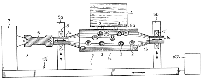
The apparatus which is shown in FIG. l
comprises an elongated horizontal shaft 1 having two
coaxial stubs la and a larger-diameter central portion
lb ~ith a cylindrical peripheral surface lc. The stubs
la are mounted in bearings 5 which are provided in
verticallv movable supports Sa and ~b serving as a
means for moving the shaft l up and down so that the burr
cutting tools 2 at the peripheral surface lc can be moved
into material removing engagement with a burr 8a at the
underside of a semifinished metallic product 4 at a level
above the improved apparatus. The supports 5a and 5b
are movable relative to a frame 105 which further
carries a reversible variable speed drive 7 serving
as a means for rotating the shaft 1 at several speeds
2 ~
in clockwise and counterclockwise direction.s through
the medium of a universal joint emplo~ying a eardan shaft
6. ~he exact nature of the rotating means 7 forms no
part of the invention; such rotating means can employ a
reversible variable-speed electric motor or two variable-
speed electric motors one of which serves to rotate the
shaft 1 in a clockwise direction and the other of which
is put to use when the shaft 1 is to be rotated in a
counterclockwise direction. The entire frame 105 with
the supports 5a, 5b and rotating means 7 can be pulsated,
oseillated or otherwise reciprocated in the axial direction
of the shaft 1 by a unit 107 which can employ an eccentric
or the like, not specifically shown.
The distribution of round cylindrical cutting
tools 2 at the peripheral surfaee 1G of the shaft 1 is
- such that the ax~s of ~airs of tools 2 are loeated in
planes whieh include the axis of rotation of the shaft 1.
FIG. 3 shows that the tools 2 are staggered in the axial
direction as well as in the peripheral or circumferential
direction of the shaft 1. This ensures that, when an
e~on~ated burr 8a or 8~ tFIG. 2) is to be removed from a
semifinished metallic product 4 (e.g., a steel block or
slab), and such burr is parallel or nearly parallel to
the axis of rotation of the shaft 1, it is acted upon
and comminuted or fragmentized by a substantial number
of discrete tools 2 in response to rotation of the
shaft b~ the rotating means 7 while the produet 4 is
held at a standstill at a level above the shaft 1.
FIGS. 1 and 3 show that the shaft 1 further
carries a number of spaeed-apart product transporting
-- 7 --
or entraining elements 3 in the form of knobs which
project from the peripheral surface lc of the shaft
portion lb and can serve as a means for transporting
the ~roduct 4 along a path which extends at right
angles to the axis of the shaft. The entrainin~ or
transporting elements 3 become effective upon
completed removal of one or more hurrs 8a, 8b.
The burrs 8a, 8b at the underside of the
product 4 which is shown in FIGS. 1 and 2 are removed
in the following way: The supports 5a, 5b are lowered to
maintain the shaft 1 in a lower end position and the
product 4 (e.g., a steel ingot or slab arriving from a
flame cutting station) is caused to advance above the
lowered shaft 1 at a level such that the burr 8a is caused
to come to a halt when it is located at a level directly
above and is substantially parallel t~ith and close to the
axis of the shaft 1. The product 4 can be supported by
a customary roller table (not shown) if the improved
burr removing apparatus is installed in a rolling mill.
The product 4 is then maintained in the aforedescribed
position in which the burr 8a is adjacent to the apex oE
the peripheral surface lc and is substantiallv parallel
with the axis of rotation of the shaft 2. The motor or
~otors (e.g., fluid-operated hydraulic cvlinder and piston
units) which move the supports 5a, 5b are then actuated to
lift the shaft 1 before the rotating means 7 is set in
motion to drive the shaft through the medium of the
cardan shaft ~. A single full revolution of the shaft
1 suffices to ensure that each of the axially stag~ered
cuttin~ or separating tools 2 engages and removes an
2 ~
adjacent portion of the burr 8a so that the latter is
broken up into a number of short pieces or fra~ments in
the course of a single removing or separating step.
The next step involves lowering the shaft 1 by the
supports 5a, 5b, and the rolling table for the product
4 is then set in motion to advance the burr 8b to the
position previously occupied bv the alreadv removed burr
8a. The supports 5a, 5b thereupon lift the shaft 1 and
the rotating means 7 is started to ensure that the shaft
1 completes at least one full revolution ~hich results
in removal and simultaneous comminution or fragmentizing
of the burr 8b into a substantial number of shorter pieces
or fragments. It is preferred to change the direction
of rotation of the shaft 1 for removal of the burr 8b.
The shat 1 of FIG. 2 is ready to be rotated
in a counterclockwise direction in order to ensure that
its tools 2 remove the 8a which is located at the topmost
portion of the peripheral surface lc and is parallel or
nearly parallel to the axis of rotation of the shaft 1.
The burr 8a adheres ~o the product 4 at the locus which
is pinpointed at 9, and such burr is brittle so that
it is readily broken up by the axiallY staggered tools
4 during rotation of the shaft 1 in a countercloc~wise
direction. The lower front edge of the thus treated
product 4 is smooth or substantiallv smooth because it
has been relieved of the burr 3a. The product 4 is then
advanced to the left so as to move the burr 8b to the
pOSitiOh previousl~ occupied by the alread~ removed burr
8a, and the shaft 1 is then raised to the level of ~IG. 2
3Q before it is set in rotaty motion to ensure that its
_ g _
tools 2 remove and brea~ the burr ~b wherebv the removed
particles or fragments of such burr are propelled in a
direction to the right, i.e., be~70nd the rear end face
of the product 4.
Since the tools 2 are sub~ect to wear, they
are preferablv separablv but reliably secured to the
central portion lb of the shaft 1 so that the~t project
beyond the peripheral surface lc. As can be seen in FIG.
2, the shaft 1 can carry two or more types of different
tools or two or more sets of dif~erently mounted tools.
The left-hand tool 2 of FIG. 2 is mounted for limited
movement in the radial direction of the axis of rotation
of the shaft 1 and is biased to an outer end position bv
a coil spring 10 at the bottom of a radial blind bore ld
in the peripheral surface lc. The means for limiting
the extent of radially outward mo~ement of the left-
hand tool 2 of FI~. 2 is the head of a threaded bolt 11
which serves as a means for separably but reliablv
securing the left-hand tool 2 of FIG. 2 to the central
portion lb of the shaft 1. ~he right-hand cutting tool
2' of FIG. 2 is not biased bv one or more springs and is
held against rotation about the axis of the respective
bolt 2 by a pin 12 which is recessed into the shaft
portion lb as well as into the tool 2'. The tools 2 and
2' are cylinders having circular outlines.
Instead of or in addition to supporting round
cutting tools 2 and/or 2', the central portion lb of the
shaft 1 can carr,y one or more polvgonal (e~g., rectangular
or s~uare) tools (one shown in ~I~. 5, as at 102) which
are partiallv recessed into complementary sockets of the
-- 10 --
~ ~3 ~3 ~
shaft portion lb and are held against radial movement b~r
threaded bolts ll.
FIG. 6 shows that the shaft portion lh car.
support at least one oblong (e.g., substantialli~ elliptical)
cutting tool 202 in a complementary socket of the
peripheral surface lc. All cutting tools can extend
substantially radially of the shaft portion lb and
outwardly beyond the peripheral surface lc of the shaft 1.
An advantage of spring biased tools (such as the
left-hand tool 2 of FIG. 2) is that they can yield in
response to engagement with the ad~acent underside of a
product 4 but are biased radially outwardl~ of the axis
of rotation of the sahft 1 to reliabl~ engage a burr 8a
or 8b and to break the adjacent portion of the burr awa~
from the major part of the product 4 in response to
rotation of the shaft 1.
The distrihution of tools on the central
portion lb of the shaft l can depart from that which is
shown in FIG. 3. For exam~le, the tools can be arra~red
in rows of three or more tools and each such row can
extend in parallelism with the axis of rotation of the
shaft l. ~hen the shaft l is driven to orbit the tools
about its axis; each tool breaks from the burr 8a or 8b
a piece which need not be longer or much longer than the
diameter of a round tool~ Since the tools are staggered
in the axial direction of the shaft 1, the burr 8a or 8b
is broken up into a large number of small pieces and the
remaining portions of the burr are hroken off as a
result of axial reciprocatory movement of the shaft
under the action of the drive 107. The transporting
elements 3 support the product 4 upon completion of a
burr removing operation and can also assist in, or carry
out, the transport of the product to move the burr 8b
to the position which was previously occupied b~ the
already removed burr 8a, or to advance the completely
deburred product 4 beyond the deburring station.
FIG. 4 shows that the improved apparatus
can be used with equal or similar advantage for removal
of burrs 8a from curved metallic products 4. Longitudinally
spaced apart portions of the illustrated burr ~a at the
underside o~ the curved product 4 are removed by pairs of
aligned cutting tools 2. This has been found to ensure
rapid and highly reliable removal of burrs from such
metallic products.
The improved apparatus is susceptible of many
additional modifications. ~`or example, the drive 107
can be designed in such a way that the shaft l is in
continuous motion in a direction to the left or to the
right while its cutting tools remove a burr 8a or 8b from
the underside of an adjacent semifinished metallic product
4.
An important advantage of the improved apparatus
is its simplicity. Thus, save for the provision of one
or more spring biased cutting tools (if such tools are
used at all), all parts which are carried by the shaft 1
can be fixedly secured to the central portion lb to thus
- contribute to simplicity, compactness and lower cost of
the apparatus~ Morèover, the apparatus can brea~ up
elongated hurrs into relatively short particles or fragments
so that the disposal of removed and simultaneously
- 12 -
2 ~
fragmenti2ed burrs is much simpler and less expensive than
the disposal of elongated burxs. The maintenance cost of
the improved apparatus is minimal, and the shaft 1 need
not carrv any moving parts.
- 13