Note : Les descriptions sont présentées dans la langue officielle dans laquelle elles ont été soumises.
2054989
`~ .
DIFFERENTIAL PRESSURE REGULATOR
BACKGROUND OF THE INVENTION
Field of the Invention
- 5 The present invention relates to pressure
regulators, and more particularly relates to
regulators which maintain a fixed pressure
difference between two separate areas. More
particularly the invention relates to a differential
pressure regulator which contains fewer parts and is
simpler in construction that conventional
differential pressure regulators. More
particularly, the invention relates to a
differential pressure regulator for controlling a
desired pressure difference under static conditions.
Related Art
Pressure regulators for maintaining a
desired pressure under changing conditions of flow
have been known in the art for many years.
Additionally, spring biased additive pressure
regulators are also old in the art. One example of
a spring biased additive
2054989
1 pressure regulator is a FAIRCHILD Model 15 or 15S positive biased
2 relay. The theory of operation of such spring biased additive
3 pressure regulators as embodied in the FAIRCHILD Model 15 or 15S
4 is that an adjustable spring adds a force to the signal or
sensing side of a diaphragm assembly. This necessitates that the
6 supply pressure cause a force greater than the signal to close
7 the regulator when the signal pressure increases. If the signal
8 pressure decreases, less force from the supply source is needed
9 to close the regulator. In flow conditions, the regulator may
also be used to throttle the outlet fluid to maintain the desired
11 downstream pressure. In static conditions the regulator will
12 always be closed so long as the pressure difference is as desired
13 -- at the set point. Under such static conditions, the regulator
14 will only open in response to an increase in the signal pressure
and then close again when the set point is achieved.
16 Additionally, there must be some means provided to vent the
17 excess outlet pressure when the signal pressure decreases,
18 especially in static pressure conditions.
19 In order to achieve the desired result, the moving trim or
spindle within the regulator must be balanced in some fashion to
21 prevent movement in response to changes in supply pressure only.
22 In the FAIRCHILD positive biased relays referenced above a
23 balance diaphragm is attached to the side of the trim opposite
24 the seat to assure that the forces acting on the upper and lower
ends of the trim due to the supply pressure are equal.
26 It is an advantage of the present invention that a
`- 2~549~9
differential pressure regulator is provided having a
simplified construction which does not require the
special balancing diaphragm of the prior art.
SUMMARY OF THE INVENTION
The present invention is a differential
pressure regulator having a spring biased diaphragm
assembly which acts against an oppositely spring
biased flow spindle. The diaphragm assembly
comprises two diaphragms separated by spacer rings
and held together by a central bolt. The upper
surface of the top diaphragm is exposed to the
signal pressure, and the lower surface of the lower
diaphragm is exposed to the outlet pressure. An
adjustable spring is situated above the upper
diaphragm to provide an additional or additive
downward force on the upper diaphragm. A vent is
provided through the central bolt and spacer rings.
The upper end of the flow spindle blocks the vent in
the central bolt so long as the signal pressure plus
the spring pressure is greater than or equal to the
outlet pressure.
The balancing of the flow spindle is
achieved by a one piece spindle omitting a balance
diaphragm and having seating surfaces that in the
closed position are substantially equal to provide
equalizing forces and an internal fluid passageway
20S~989
to allow the pressure above and below the spindle to
equalize when it opens.
Therefore, in accordance with the present
invention, there is provided a differential pressure
regulator comprising:
(a) a valve body having inlet and outlet
ports in fluid communication with each other through
a flow chamber;
(b) a pressure balanced spindle of single
piece construction slidably mounted within said flow
chamber and biased to seat within said flow chamber
to block fluid communication therethroughi
(c) a diaphragm assembly mounted on said
body and in contact with said spindle to press on
and unseat said spindle in response to forces acting
on said diaphragm assembly, said diaphragm assembly
being in fluid communication with said outlet porti
(d) a spring bonnet mounted on said body
above said diaphragm assembly having a bias pressure
feed-back port in fluid communication with said
diaphragm assembly and containing an adjustable
biasing spring in contact with said diaphragm
assembly to provide a force additive to that
provided by pressure entering said bias pressure
feed-back port; and
(e) vent means through said diaphragm
assembly which acts in response to fluid vapor
2054989
_
pressure from said outlet port which is higher than
the force of said adjustable biasing spring and
pressure entering said bias pressure feed-back port.
Also, in accordance with the present
invention, there is provided a differential pressure
regulator comprising:
(a) a valve body having inlet and outlet
ports in fluid communication with each other through
a flow chamberi
(b) a pressure balanced valve spindle of
single piece construction slidably mounted within
said flow chamber and biased to seat within said
flow chamber to block fluid communication
therethrough and comprising three axially aligned
and connected cylindrical segments of decreasing
diameter, the first and largest diameter segment
defining a lower seating and guide chamber therein
and having an internal annular groove to receive a
first O-ring seal, the second segment defining a
spring receptacle chamber therein and having a bore
normal to and through said second segment and said
spring receptacle chamber, the third and smallest
diameter segment defining an actuator stem, and an
external annular groove between said first and
second segments to receive a second O-ring seal;
(c) a diaphragm assembly mounted on said
body and in contact with said spindle to press on
3b
k
- 2~5~98~
and unseat said spindle in response to forces acting
on said diaphragm assembly, said diaphragm assembly
being in fluid communication with said outlet port
and comprising an upper diaphragm and a lower
diaphragm connected together by a central bolt and
separated by inner and outer spacer rings,
(d) a spring bonnet mounted on said body
above said diaphragm assembly having a bias pressure
feed-back port in fluid communication with said
diaphragm assembly and containing an adjustable
biasing spring in contact with said diaphragm
assembly to provide a force additive to that
provided by pressure entering said bias pressure
feed-back porti and
(e) vent means comprising an aperture
through said central bolt and vent holes through
said inner and outer spacer rings, said actuator
stem blocking said aperture when the force of said
adjustable spring and pressure entering said bias
pressure feed-back port is equal to or higher than
the force on said diaphragm from the fluid vapor
pressure from said outlet port.
Still in accordance with the present
invention, there is provided a differential pressure
regulator comprising:
~ 20S4989
(a) a valve body having inlet and outlet
ports in fluid communication with each other through
a flow chamber;
(b) a pressure balanced spindle of single
piece construction slidably mounted within said flow
chamber and biased to seat within said flow chamber
to block fluid communication therethrough, said
pressure balanced valve spindle comprising three
axially aligned and connected cylindrical segments
of decreasing diameter, the first and largest
diameter segment defining a lower seating and guide
chamber therein and having an internal annular
groove to receive a first O-ring seal, the second
segment defining a spring receptacle chamber therein
and having a bore normal to and through said second
- segment and said spring receptacle chamber, the
third and smallest diameter segment defining an
actuator stem which is in contact with a diaphragm
assembly, and an external annular groove between
said first and second segments to receive a second
O-ring seal;
(c) said diaphragm assembly mounted on
said body and in contact with said spindle to press
on and unseat said spindle in response to forces
acting on said diaphragm assembly, said diaphragm
assembly being in fluid communication with said
outlet port;
3d
,f~''`'
205~989
(d) a spring bonnet mounted on said body
above said diaphragm assembly having a bias pressure
feed-back port in fluid communication with said
diaphragm assembly and containing an adjustable
biasing spring in contact with said diaphragm
assembly to provide a force additive to that
provided by pressure entering said bias pressure
feed-back port; and
(e) vent means through said diaphragm
assembly which acts in response to fluid vapor
pressure from said outlet port which is higher than
the force of said adjustable biasing spring and
pressure entering said bias pressure feed-back port.
Still further in accordance with the
present invention, there is provided a differential
pressure regulator comprising:
(a) a valve body having inlet and outlet
ports in fluid communication with each other through
a flow chamber;
(b) a pressure balanced valve spindle of
single piece construction slidably mounted within
said flow chamber and biased to seat within said
flow chamber to block fluid communication
th~erethrough and comprising three axially aligned
and connected cylindrical segments of decreasing
diameter, the first and largest diameter segment
defining a lower seating and guide chamber therein
3e
i,
2054989
and having an internal annular groove to receive a
first O-ring seal, the second segment defining a
spring receptacle chamber therein and having a bore
normal to and through said second segment and said
spring receptacle chamber, the third and smallest
diameter segment defining an actuator stem, and an
external annular groove between said first and
second segments to receive a second O-ring seal;
(c) a diaphragm assembly mounted on said
body and in contact with said spindle to press on
and unseat said spindle in response to forces acting
on said diaphragm assembly, said diaphragm assembly
being in fluid communication with said outlet port
and comprising an upper diaphragm and a lower
diaphragm connected together by a central bolt and
separated by inner and outer spacer rings;
(d) a spring bonnet mounted on said body
above said diaphragm assembly having a bias pressure
feed-back port in fluid communication with said
diaphragm assembly and containing an adjustable
biasing spring in contact with said diaphragm
assembly to provide a force additive to that
provided by pressure entering said bias pressure
feed-back port; and
(e) vent means comprising an aperture
through said central bolt and vent holes through
said inner and outer spacer rings, said actuator
~.
- 20S~989
stem blocking said aperture when the force of said
adjustable spring and pressure entering said bias
pressure feed-back port is equal to or higher than
the force on said diaphragm from the fluid vapor
pressure from said outlet port.
Still further in accordance with the
present invention, there is provided a differential
pressure regulator comprising:
(a) a valve body having inlet and outlet
ports in fluid communication with each other through
a flow chamber;
(b) a pressure balanced valve spindle of
single piece construction slidably mounted within
said flow chamber and biased to seat within said
flow chamber to block fluid communication
therethrough comprising:
(i) a cylindrical base defining a lower
seating and guide chamber therein and having an
internal annular groove within said lower seating
and guide chamber;
(ii) a first cylindrical projection
extending from the upper surface of said base, said
first cylindrical projection being of smaller
diameter than and in axial alignment with said base
and defining a spring receptacle chamber therein,
said spring receptacle chamber being in fluid
3g
i ".j
- 2n5~989
communication with said lower seating and guide
chamber;
(iii) an actuator stem projecting from
the upper surface of said first cylindrical
projection, said actuator stem being cylindrical and
of smaller diameter than said first cylindrical
projection;
(iv) an external groove on said first
cylindrical projection directly adjacent the upper
surface of said base; and
(v) a bore through said first
cylindrical projection and said spring receptacle
chamber;
(c) a diaphragm assembly mounted on said
body and in contact with said spindle to press on
and unseat said spindle in response to forces acting
on said diaphragm assembly, said diaphragm assembly
being in fluid communication with said outlet port;
(d) a spring bonnet mounted on said body
above said diaphragm assembly having a bias pressure
feed-back port in fluid communication with said
diaphragm assembly and containing an adjustable
biasing spring in contact with said diaphragm
assembly to provide a force additive to that
provided by pressure entering said bias pressure
feed-back port; and
3h
" ~
20S~g89
" -
(e) vent means through said diaphragm
assembly which acts in response to fluid vapor
pressure from said outlet port which is higher than
the force of said adjustable biasing spring and
pressure entering said bias pressure feed-back port.
Still further in accordance with the
present invention, there is provided a differential
pressure regulator comprising:
(a) a valve body having inlet and outlet
ports in fluid communication with each other through
a flow chamber;
(b) a pressure balanced valve spindle of
single piece construction slidably mounted within
said flow chamber and biased to seat within said
flow chamber to block fluid communication
therethrough comprising:
(i) a cylindrical base defining a lower
seating and guide chamber therein and having an
internal annular groove within said lower seating
and guide chamber, the diameter of said lower
seating and guide chamber below said internal
annular groove is wider than the diameter of said
lower seating and guide chamber above said internal
annular groove;
(ii) a first cylindrical projection
extending from the upper surface of said base, said
first cylindrical projection being of smaller
_ 205~989
diameter than and in axial alignment with said base
and defining a spring receptacle chamber therein,
said spring receptacle chamber being in fluid
communication with said lower seating and guide
chamber;
(iii) an actuator stem projecting from
the upper surface of said first cylindrical
projection, said actuator stem being cylindrical and
of smaller diameter than said first cylindrical
projection;
(iv) an external groove on said first
cylindrical projection directly adjacent the upper
surface of said basei
(v) first and second O-ring seals
disposed in said internal and external annular
grooves, respectively, exposing a portion of each of
said O-ring seals and
(vi) a bore through said first
cylindrical projection and said spring receptacle
chamber; wherein the lower surface area of said base
plus the exposed surface area of said first O-ring
seal is substantially equal to the upper surface
area of said base not covered by said second O-ring
seal plus the exposed surface area of said second
0-ring seal;
(c) a diaphragm assembly mounted on said
body and in contact with said spindle to press on
205~989
._
and unseat said spindle in response to forces acting
on said diaphragm assembly, said diaphragm assembly
being in fluid communication with said outlet port;
(d) a spring bonnet mounted on said body
above said diaphragm assembly having a bias pressure
feed-back port in fluid communication with said
diaphragm assembly and containing an adjustable
biasing spring in contact with said diaphragm
assembly to provide a force additive to that
provided by pressure entering said bias pressure
feed-back port; and
(e) vent means through said diaphragm
assembly which acts in response to fluid vapor
pressure from said outlet port which is higher than
the force of said adjustable biasing spring and
pressure entering said bias pressure feed-back port.
BRIEF DESCRIPTION OF THE DRAWINGS
FIG. 1 is a top view of the preferred embodiment
of the differential pressure regulator of the
20present invention.
FIG. 2 is an elevational view in cross sectional
view taken along
3k
- 205~1989
1 line 2-2 of Fig 1.
2 FIG. 3 is an elevational view in partial cross section of the
3 special pressure balanced spindle used in the preferred
4 embodiment of the differential pressure regulator of the
present invention.
6 FIG. 4 is a bottom plan view of the special pressure balanced
7 spindle used in the preferred embodiment of the differential
8 pressure regulator of the present invention.
g FIG. 5 is a top plan view of the special pressure balanced
spindle used in the preferred embodiment of the differential
11 pressure regulator of the present invention.
12 FIG. 6 is a schematic diagram of one use of the differential
13 pressure regulator of the present invention.
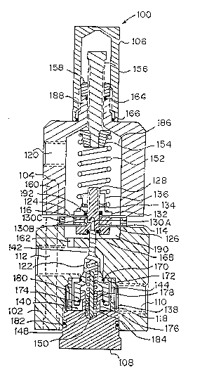
14 DESCRIPTION OF THE PREFERRED EMBODIMENT
For a detailed description of the preferred embodiment the
16 reader is directed to the accompanying drawings in which like
17 components are given like numerals for ease of reference.
18 A detailed mechanical description is given in FIG. 2 which
19 is an elevational view in cross section and FIG. 1 which is a top
view. The differential pressure regulator, generally indicated
21 at 100, is seen to comprise a cylindrical body 102 and a
22 cylindrical spring bonnet 104 axially aligned and mounted on the
23 body 102 with assembly screws 160 (only one shown) oriented as
24 shown in FIG. 1. Between the body 102 and the spring bonnet 104
are located upper diaphragm 124 and lower diaphragm 126 which are
26 separated by inner spacer ring 116 and outer spacer ring 114.
~ 205~989
1 Directly above and adjacent the upper diaphragm is lower bonn-et
2 spring guide 132. The two diaphragms 124 and 126 and the two
3 spacer rings 114 and 116 are held together by central bolt 128,
4 nut 136 and lock washer 134. For reasons to be discussed below,
the central bolt and spacer rings are provided with bleed holes
6 130A, 130B and 130C respectively. The bleed hole 130A in the
7 central bolt 128 begins at the bottom and continues at a right
8 angle to provide a vent between the diaphragms 124 and 126.
g Looking now at the body 102 of the regulator 100, at the
lower end thereof there is seen to be a body plug 108 inserted as
11 by threads through the bottom surface and sealed therein by 0-
12 ring seal 182. The body plug 108 is shown to include an
13 extension 176 from the top surface having a T type head 178.
14 Within the body 102 there is a coaxial cylindrical lower body
cavity 140 and a coaxial upper body cavity 142 or dome of smaller
16 diameter than the lower body cavity 140. Together the lower body
17 cavity 140 and upper body cavity 142 make up the flow chamber
18 within which is mounted the spindle 122 and body plug 108.
19 Supply inlet 110 is provided normal to the lower body cavity 140
and outlet 112 is provided normal to upper body cavity or dome
21 142. Directly below the lower diaphragm 126 and formed in the
22 upper end of body 102 is chamber 190 which is in fluid
23 communication with outlet 112 via internal passageway 162.
24 Strainer screen 138 is provided within the lower body cavity 140
so as to cover the inlet 110. Spacer ring 118 is located within
26 the lower body cavity 140 to assure the correct distance between
`- 205~989
1 the upper surface of the body plug 108 and the surface 172 of the
2 upper end of the lower body cavity 140.
3 The special pressure balanced spindle 122 is snugly mounted
4 about the T type head 178 by lower spindle cavity 144 for
rectilinear movement within the body cavities 140 and 142.
6 Additionally, the spindle 122 includes an upper spindle cavity
7 146 which acts as the upper receptacle for spindle spring 148.
8 The lower end of the spindle spring 148 is housed in body plug
9 spring receptacle 184. Spindle spring guide pin 150 provides
lateral stability for spindle spring 148. The spindle is
11 provided with two seating surfaces within the lower body cavity
12 140. The upper seating surface comprises O-ring seal 170 which
13 seats against the surface 172 between the two body cavities 140
14 and 142. The lower seating surface comprises a second O-ring
seal 174 which seats against the underside of T type head 178.
16 The spindle 122 is biased upward by the spindle spring 148 to
17 engage the sealing surfaces and block the flow chamber. A more
18 detailed description of the special spindle is contained below
19 with reference to FIG.'s 3-5. The top end of spindle 122 is
shown seated in and blocking the lower end of the center bolt
21 bleed hole 13OA with the aid of O-ring seal 168.
22 The spring bonnet 104 is shown to have coaxial bonnet cavity
23 186 to which the signal or bias pressure feed-back port 120 is
24 connected at a right angle. Bonnet spring 152 is mounted within
bonnet cavity 186 and held in place at the lower end by lower
26 bonnet spring guide 132. The lower bonnet spring guide 132 is
205~989
1 held in place by aforementioned central bolt 128, lock washer 134
2 and nut 136. Interposed between the lower surface of bonnet
3 spring spacer 132 and upper diaphragm 124 and about bolt 128 is
4 O-ring seal 192. At the upper end the bonnet spring 152 is
retained by bonnet spring button 154 which is connected to
6 adjusting screw 156 which is threadedly inserted through upper
7 extension 188 of bonnet 104. The Adjusting screw 156 is provided
8 with jam nut 158 for locking the adjusting screw 156 in the
9 desired position. The jam nut 158 is provided with O-ring seal
164 preferably of TEFLON to prevent the escape of vapors
11 entering the bonnet cavity 186 through the bias pressure feed-
12 back port 120. In the event that the sensed vapors entering the
13 feed-back port 120 are dangerous additional sealing is provided
14 by cap 106 which is threadedly connected about upper bonnet
extension 188 and sealed thereon by O-ring seal 166.
16 Referring now to FIG.'s 3-5 more detail of the pressure
17 balanced spindle is shown. The O-ring seals 170 and 174 are
18 shown in dotted lines as they appear in the earlier FIG.'s. The
19 pressure balanced spindle, generally indicated at 122, is shown
to comprise three axially aligned cylindrical segments of
21 decreasing diameter.
22 The first and largest diameter segment comprises the base
23 301 within which is the lower spindle cavity 144 which acts as
24 the lower sealing and spindle guide chamber. Internal annular
groove 174A is provided to receive the O-ring 174 which makes up
26 the lower seal. Bore 309 is of slightly larger diameter than
~ 20S~989
1 lower spindle cavity 144 to allow expansion of the 0-ring 174 as
2 it seats.
3 The second segment 303 contains the upper spindle cavity 146
4 which acts as the spindle return spring receptacle chamber and
the important pressure balancing ports 373 which comprise a bore
6 normal to and through the second segment 303 and the upper
7 spindle cavity 146. Between the first and second segments there
8 is provided an external annular groove 170A to receive and hold
9 the O-ring 170 which makes up the upper seal.
The third and smallest diameter segment is the actuator stem
11 390 which is in contact with the lower surface of central bolt
12 128 for moving the spindle up and down within the valve body.
13 Surfaces 317, 319 and 321 are machine dressing. Surfaces 313 and
14 315 are tapered to provide strength between segments.
Additionally, surface angle 313 matches the surface angle within
16 the upper body cavity 142 which is the result of the boring
17 process. Surfaces 327 and 305 are simply the result of the
18 boring process to produce the lower spindle cavity 144 and the
19 return spring receptacle 146.
The two important features of the pressure balanced spindle
21 are: 1) that the seating surfaces in the closed position be
22 substantially equal to provide equalizing forces; and 2) that
23 there is an internal fluid passageway to allow the pressure above
24 and below the spindle to equalize when it opens. The upper
pressure responsive surface when closed comprises the exposed
26 surface of 0-ring 170 and the exposed upper surface 325 of base
. 20S4989
1 301. The lower pressure responsive surface when closed comprises
2 the exposed surface of 0-ring 174 and lower surface 329 of base
3 301. The internal fluid passageway is made up of bore 309, lower
4 spindle cavity 144, upper spindle cavity 146 and ports 373.
Referring now to FIG. 6 there is shown in schematic form one
6 use of the differential pressure regulator of the present
7 invention. The particular use shown is to maintain the
8 differential pressure across a packing gland 212 around a
9 rotating shaft to prevent leakage and prolong the life of the
gland.
11 In the embodiment shown in FIG. 6 there is shown a closed
12 stirred tank 202 containing a liquid 214 and having a vapor space
13 208 above the liquid level. The liquid 214 within the tank 202
14 is stirred by agitator 204 having a rotating shaft 206 which
passes through packing gland 212 at the top of the tank 202. A
16 differential pressure gauge 210 is connected between the vapor
17 space 208 and the outer packing volume 216.
18 The vapor space 208 is in fluid communication with the bias
19 pressure feed-back port 120 via line 218. The outer volume 216
of the packing gland 212 is in fluid communication with the
21 regulator outlet 112 via line 220. In the following example a
22 differential pressure of 10 pounds per square inch (psi) is
23 desired across the packing gland 212, i.e, the pressure in outer
24 packing gland volume 216 is desired to be 10 psi higher than the
pressure in the vapor space 208.
26 In operation the differential pressure regulator is first
205~989
1 set to a 10 pounds per square gauge (psig) output via the
2 adjusting screw 156 without any feed-back pressure by temporarily
3 disconnecting the feed-back line 218. The differential pressure
4 gauge 210 may be used to set the regulator by disconnecting the
gauge from the feed-back line. At this point, after the lines
6 have been reconnected, the regulator will apply 10 psig on top of
7 the packing when the pressure in the vapor space is atmospheric
8 or zero gauge.
g When the vapor space pressure rises above zero it adds to
the set pressure spring force, pound for pound, and increases the
ll output pressure of the regulator to 10 psig plus the vapor space
12 pressure, therefore maintaining a differential pressure of 10 psi
13 across the packing. When the vapor space pressure goes to
14 vacuum, an upward force is exerted on the upper diaphragm 124
(the two diaphragms being connected by the central bolt 128) and
16 the downward force of the spring is decreased pound for pound.
17 The regulator output pressure is then 10 psig minus the vapor
18 space pressure, still maintaining a 10 psi differential pressure
19 across the packing. In the embodiment shown here the ratio of
diaphragm areas is the same so that the outlet pressure is 1:1 to
21 the change in vapor space pressure. By adjusting the diaphragm
22 ratios the output pressure is similarly adjusted, e.g. by
23 reducing the area of lower diaphragm 126 to one-half that of
24 upper diaphragm 124 the output pressure is twice the signal
pressure plus the spring force.
26 Because the output of the regulator is in a dead ended
2054989
1 service, provision must be made to bleed off excess pressure on
2 the packing whenever it occurs- Such excess pressure on the
3 packing tends to occur whenever the vapor space pressure is
4 decreasing. When this happens, the diaphragm assembly is lifted
upward off of the upper tip of the spindle 122 due to the higher
6 force under the lower diaphragm 126 than the combined spring and
7 vapor space pressure force on top of the upper diaphragm 124.
8 The tip of the spindle 122 is thus unseated from the lower
g opening of the central bolt vent hole 130A allowing the excess
pressure on the packing to escape to the atmosphere through the
11 vent 130 which comprises vent holes 130A and the vent holes 130B
12 and 130C in the inner and outer spacer rings respectively. The
13 bleed port will close when the upward and downward forces across
14 the diaphragms are in balance again.
The design allows only small amounts of the blanketing gas,
16 such as nitrogen, to escape into the atmosphere, and this happens
17 only when the vapor space pressure decreases. The differential
18 pressure regulator of the presènt invention is not a constant
19 bleed device. The vapor space pressure is retained in the
system and is not discharged to the atmosphere. This latter is a
21 safety feature in case the vapor is toxic.