Note : Les descriptions sont présentées dans la langue officielle dans laquelle elles ont été soumises.
LIQ~ID HYDROCARBON S~IMMER SYSTEMS AND METHODS O~
MONITORI~G LEAKS IN HAZAR O~S LIQ D rrANKS
This invention relates to automatic skimming and
monitoring systems which are particularly adapted for
monitoring underground fuel tanks at service stations. State
laws in many jurisdictions require that there be a periodic
monitoring of such tanks in a manner to achieve a leak
detection of as little as .05 gallons per hour and, of course,
many operators, concerned with environmental considerations
and eliminating potentially explosive conditions, are also
desirous of removing hydrocarbon liquids which have leaked
into the ground and may be contaminating ground water. The
present invention is concerned with protecting tanks of the
type disclosed in U.S. patents 4,571,987; 4,649,739; 4,739,648;
and 4,885,931 which, of course, may contain diesel fuel oils
and other hydrocarbon liquids, as well as gasoline. Monitoring
wells are often used adjacent to such underground tank sites
for the purpose of sampling the ground water from time to
time to determine if there has been any leakage of the stored
product. Such monitoring wells are frequently used, for
example, when a secondary barrier is constructed around the
site and its monitoring wells, which is sufficiently thick
and impermeable with respect to the substance stored so that
any releases from the tank are directed to one of the
monitoring wells. Underground water monitoring regu;ations
normally require that the regulated liquid be im~iscible in
water and have a specific gravity of less than one. Further,
the ground water must never be more than twenty feet from the
ground surface and the soils between the underground tank and
monitoring wells must consist of gravels, course to medium
sands, course silts, or other permeable materials. Such wells
must allow the entry of regulated substances on the water
l ~
¦ table into the well under both high and low ground-water
conditions.
The system of the present invention is constructed
to continuously and automatically remove floating hydrocarbons
from the ground water surface in a monitoring well without the
¦ necessity of employing expensive electronics, pumps, or valves,
and incurring labor costs. The system need only be checked
¦ periodically to see whether hydrocarbons have filtered into
the collection chamber. If the chamber needs emptying, it is
a simple matter to removing the skimming system from the well
¦ and drain the hydrocarbon liquids back into the storage tank.
The necessity of pumping a mixture of water and liquid hydro-
carbons, and disposing of it at a remote site, is avoided
with the present system. When used in monitoring wells, the
buoyancy of the skimmer system must be carefully controlled
so that it floats with a predetermined portion of its upper
end projecting a predetermined distance above the ground
water level. The present skimmer system includes a vertically
disposed tubular housing having an upper end providèd with
passages to admit hydrocarbon liquid floating on the surface
of the water table. At its lower end, the system provides a
lower collection chamber for recovered hydrocarbon liquid and,
disposed between this collection chamber and the passages, is
a filter separator which will pass only the hydrocarbon liquid
to the collection chamber. The separator utilizes a filter
element, and a wick associated with the filter element to
draw the hydrocarbon liquid to the filter. It further provides
for the removal of air from the collection chamber as the
chamber fills.
One of the prime objects of the present invention is
.?~
to provide a reliable, yet simple and inexpensive, system
which accomplishes the dual function of monitoring the monitor
well in which it is used, while at the same time receiving
¦ hydrocarbon liquids which may have leaked into the ground
¦ water and separating them from the ground water so that they
¦ can be simply drained back into the tank.
¦ A further object of the invention is to provide a
¦ floating skimmer system for monitor wells which is so weighted
¦ that its upper end with the filter element floats on the water
¦ table liquid.
¦ Still another object of the invention is to so
¦ support the skimming system, when a substantial volume of
¦ hydrocarbon liquids have been passed through to the collection
¦ chamber, that it does not sink and admit ground water to the
¦ collection chamber.
Another object of the invention is to provide a
skimmer system which can be adapted to the particular moni-
toring well in the sense that its buoyancy can be altered
when necessary.
Other objects and advantages of the invention will
be pointed out specifically or will become apparent from the
following description when it is considered in conjunction
with the appended claims and the accompanying drawings.
In the drawings, Figure 1 is a fragmentary, schematic,
partly sectional, elevational view of an underground storage
tank and an adjacent monitoring well, the tank being shown
greatly out of proportion for the sake of clarity of
illustration.
Figure 2 is an enlarged, fragmentary, sectional
elevational view showing the manner in which the skimmer
2 ~
system is supported within the monitoring well when the
collection chamber has filled enough to empty.
Figure 3 is a greatly enlarged, fragmentary,
¦ sectional, elevational view of the upper end of the skimmer
unit only, illustrating the construction of the separating
¦ cartridge particularly.
¦ Figure 4 is a considerably enlarged, sectional
¦ plan view taken on the line 4-4 of Figure 3.
¦ Figure 5 is a fragmentary, sectional, elevational
¦ view, similar to Figure 2, showing the manner in which the
I skimmer system is buoyantly supported when there is no liquid,
¦ or virtually no liquid, in the collection chamber, and
¦ Figure 6 is an enlarged fragmentary cross-sectional
¦ view through a typical filter element.
¦ Referring now more particularly to the accompanying
¦ drawings, a service station environment is indicated generally
¦ at 5 and is shown as having an above ground pumping station 10
¦ with a pumping conduit 11 extending down into an underground
tank T which contains a hydrocarbon liquid L such as gasoline.
The tank T is much reduced in size in Figure 1, relative to
other elements. As in the aforementioned patents, the tank T
has a fill pipe and a vapor vent pipe in the usual manner.
Provided adjacent to the tank T are one or more monitoring
wells generally designated W, which are shown as having ground
water 12 therein to a level 12a. For purposes of illustration
in Figure 2, a hydrocarbon film 13 is disclosed as floating
on the ground water surface.
The automatic skimming and monitoring system of the
present invention, which is generally designated 14, is shown
as floating on the water table liquid in Figures 1 and 5. It
20~8~q
includes an outer tubular housing, generally designated 15,
~ which has sufficient buoyancy to float with its upper end
¦ projecting a predetermined distance above the water line 12a.
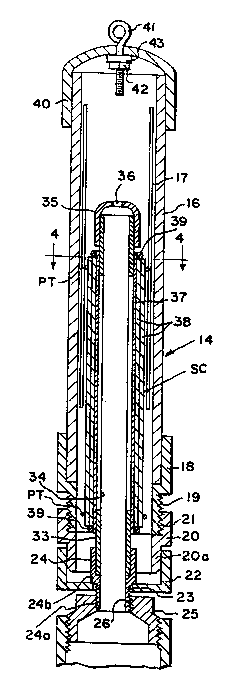
¦ As Figures 2 and 3 particularly indicate, outer housing 14 is
an assembly comprising an upper cylindrical tube 16 having
circumferentially spaced axially parallel vertical slots 17
providing passages which will admit liquid to the interior of .
tube 16. A fitting 18 receives the lower end of the tube 16
and is threaded at its lower end as at 19 so as to be received
by an oppositely disposed fitting 20, having threads 21 which
are threadedly engaged with the threaded surface l9. The
lower reduced diameter end 20a of the fitting 20 is received
by a collar 22 which has an opening 23 to pass the lower
threaded end of reduced diameter 24a of an interior, filter
cartridge support sleeve 24. The shoulder 24b of sleeve 24
is of sufficient diameter to overly the opening 23 so that
the support 24 is retained by the member 22.
A threaded cylindrical support 25 has an upper end
which is threaded as at 26 to interfit with the threaded lower
end 24a of the support sleeve 24 and from which it suspends a
lower collection chamber generally designated CL. The
collection chamber CL which forms the lower end of housing
._ assembly 15 comprises a transparent plastic cylindrical tube 27
which, as shown in Figure 2, is about half full of collected
hydrocarbon liquid 28. At its lower end, the tube 27 is
received by a lower end fitting 29, and it should be
understood that the lower end of the tube 27 is open to a tube
30 leading to a valve assembly generally designated V. Valve
assembly V is a conventional valve and includes a lever 31
which may be manipulated, i.eO, rotated, to either pass liquid
I ~ f~ "Ç~j ~
through the valve assembly V from the tube 30 or to close off
the tuhe 30.
Provided within the upper portion of the assembly 14
is a sep.~rator cartridge, generally designated SC, which is
peripherally spaced from the internal wall of tube 16 and
comprises a plastic tube 33 with its lower end received and
sealed within the fitting 24. Any suitable waterproof
adhesive may be utilized to effect the seal between the lower
end of tube 33 and the internal wall of sleeve 24. Elongate
axially parallel slots 34 are provided at circumferential
intervals in the tube 33, and the upper end of the tube 33,
above the vertical 510ts 34, is covered by a cup shaped cap
member 35 having an opening 36 in communication with the open
upper end of tube 33. The cap member 36 is similarly
adhesively secured in position with an adhesive which also
functions as an effective liquid seal.
Wrapped around tube 33 is a filter membrane 37,
and wrapped around filter 37 twice so that it has two
thicknesses is an absorbent wick 38. Both the filter 37 and
the wick 38 resist and prevent the passage of water, while
admitting and passing the much lighter liquid hydrocarbon.
Hydrocarbons with a specific gravity under one thus pass to
the interior of tube 33 and on to tube 27. It will be noted
that both the filter 37 and wick 38 are of such axial length
as to cover the slots 34 provided in the tube 33. The over-
lapped edges of the membrane film 37 which has microscopic
pores ~ are adhesively secured to one another and the ends
of film 37 protrude beyond wick 38 and are held tightly
against the tube 33 by rubber 0-rings or the like 39. The
wick 38 is a polypropylene paper toweling with each layer
3 ~ /l l
3/16ths of an inch in thickness and can be ordered in roll
form from Cleveland Cottonwood Products Corporation of
Cleveland, Ohio. This toweling is non-hygroscopic and tends
to shed wa~er without absorbing it. It does attract or wick
the liquid hydrocarbon. The wick can be held in wrapped
contact with the filter 37 by plastic ties PT or in any other
suitable manner. The filter membrane 37 is an inert
polytetrafluorethlyene film consisting of laminated
polytetrafluorethlyene layers. The layers 37a and 37b may be
solid with microscopic pores ~ or the radially inner one of
them may be a screen serving as a backer for the other.
Alternatively, the membrane 37 may be 37a and 37b sandwiched
between and laminated to polypropylene inner and outer backer
screen layers. The filter 37 is naturally hydrophobic and
chemically stable in the presence of hydrocarbon liquid. The
layers of the membrane 37 have a maximum pore size of 1 um
(micron) and an air permeability of 1000 ml/min/in, and pass
the hydrocarbon liquid through by capillary attraction. If
the pores ~ are greater than one micron some water gets
through, once toweling 38 becomes saturated with hydrocarbon
and some moisture reaches the membrane 37. If the pores p
are less than one micron the gasoline does not get through
in a stable state. The memhrane thickness is in the range 6-7
millimeters.
As Figure 3 particularly indicates, the_upper end of
tube 16 is closed by a cup shaped cap generally designated 40.
The cap 40 may be adhesi~ely secured to the tube 16 and carry
an attachment eye bolt 41 which has a nut 42 securing a lead
washer 43 or the like which adds a predetermined weight to
the device. As Figure 5 indicates, a light weight, i.e.
1 2 ~
aluminum, chain 44 secures to the eye bolt 41 and at its upper
end secures to an eye 45 provided on the lower end of a well
cover member 46.
The skimmer is shown initially installed in Figure
5 in a monitoring well which has a ground water level 12a
with no discernible liquid hydrocarbon content. In this
condition of the device, the buoyancy of the skimmer system
is such that the chain 44 is slacked as at 44a and the
collection tube 27 is empty. Assuming that hydrocarbon liquid
enters the monitoring well~ it will float on the surface of
the ground water as indicated at 13 in Figure 2. Both the
ground water and hydrocarbon liquid are able to enter the
interior of tube 16 through the slots 17, but the composition
of the absorbent layers 38 i5 such that it is mainly only the
hydrocarbon liquid which tends to be wicked to the filter 37
and distributed vertically over its length by wick 3B. The
filter 37 is completely chemically hydrophobic for practical
purposes and will additionally capillarily pass only the
hydrocarbon liquid through its pores to the interior of tube
33 through the slots 34. I~ this, it is aided by the pressure
of the water surrounding the members 38 and 37.
Figure 2 shows the skimmer system in a position in
which the collection chamber 27 is virtually full of liquid
and chain 44 has been extended due to the added weight of the
stored hydrocarbon liquid in the chamber 27. Chain 44 is of
such a length relative to ~he buoyancy of the skimmer system
that it will not permit the skimmer system to sink beyond a
predetermined level. For instance, if water were to enter the
tube 33 via the opening 36, the separating function of the
device would be lost. It would not then be possible to drain
2 ~
the hydrocarbon liquid separa~ed back into the tank T, once
the skimmer system was removed from the well w. This is
accomplished by removing the skimmer system from the well W
and suspending it over the opened fill pipe for tank T.
Manipulation of the handle 31 of valve V through 90, then,
opens the valve to permit the liquid from chamber 27 to be
restored to the tank T. Of course, only gasoline with
substantially no water content may be returned.
Because the tube 27 is transparent, the level of
separated hydrocarbon liquid 2B can be readily observed at
any time. The presence of separated liquid hydrocarbon can
be detected by visually inspectinq the cylinder 27. When
empty, the system floats in water with about 6 inches of its
filter element above the water line and the remaining lower
cylinder assembly providing the buoyancy required. The lead
washer 43 selected for a particular skimmer system counter-
balances this buoyancy and provides a ~ontrol which can be
varied to suit conditions. When empty, the light chain 44
should have approximately 3 inches of slack and this absence
of slack, of course, is, also, a detection indicator which can
be instantly noted. As indicated, the cartridge filter and
wick are capable of replacement when necessary. The filter 37
is protected from premature blinding by the use of the coarser
filter overlay 38 which provides contact with the filter 37
above the liquid water level in the well W as well as below it.
The migration of various fuels through members 38 and 37 is,
of course, a function of their viscosity and gasoline will
have a greater separation rate than fuel oil.
It is to be understood that the embodiments
described are exemplary of various forms of the invention
2(1~$'`~9
only and that the invention is defined in the appended claims
¦ which contemplate various modifications within the spirit and
l scope of the invention.