Note : Les descriptions sont présentées dans la langue officielle dans laquelle elles ont été soumises.
BATTERY CHARGING CABLE SYSTEM
BACKGROUND OF THE INVENTION
In the automotive field, or where there is a need for
charging an empty battery from a charged one, a pair of cables,
commonly known as booster cables, are used. These cables are
provided with two pairs of clamps for connection from one battery
to the other. In making the connection however, there is a chance
that an inexperienced person may connect the batteries with the
wrong polarity and cause damage either to the batteries, to the
cables or to his person because of excessive current passing
through the cables.
In the prior art and, in particular, in U.S. Patent No.
4,400,658 to Yates, the problem is stated but the solutions
provided are not practical. Tn the device disclosed in the above
patent, there is no provision for sensing the polarity of a very
empty battery having only millivolts of potential across its
terminals. Also, three position polar relays are described in the
above patent that are impractical because such relays cannot be
made to switch heavy currents which is a requirement for this
application. Furthermore, in the device disclosed in the above
patent, there is no provision for automatic disconnect of the
cables after removal from the battery being charged and no
monitoring and alarm circuits.
SUMMARY OF THE INVENTION
In view of the foregoing, it is the abject of the present
invention to provide an improved battery charging cable system
where, regardless of the way the system is connected, it
automatically adjusts for correct polarity, even if the battery
being charged has very low voltage acrass it.
It is yet another object of the invention to provide a
battery charging system in which there are monitoring and alarm
circuits to warn the operator of any failure of the system.
A further object of the invention is to provide a battery
charging cable system which, when the cables axe removed from the
battery being charged, disconnects power to the cables thus
eliminating the danger of either reconnecting the cables to the
battery with the wrong polarity or of a short circuit if the
disconnected cables contact one another.
Yet another object of the invention is to provide a
battery charging cable system with a special reversing relay which
provides high contact pressure with minimum actuating coil current
and which can be easily connected to the cables.
These and other objects of the invention are achieved
through provision of two pairs of booster cables having a polarity
2
controller interposed therebetween which includes a polarity
sensing circuit and a reversing relay operated by the sensing
circuit. The sensing circuit includes a differential amplifier
circuit which is electrically connected to the booster cables to
be attached to a battery to be charged. The sensitivity of the
differential amplifier circuit is high so that even a very small
voltage across a battery to be charged can be detected thereby.
Thus, the polarity of even a virtually dead battery can be
determined by the sensing circuit.
The differential amplifier circuit is connected to, and
controls, the reversing relay which is interposed between the two
pairs of booster cables and acts to switch the connections of the
cables depending on the sensed polarity of the connections to a
battery to be charged.
Also provided in the polarity sensing circuit is a
voltage or current responsive means for automatically resetting or
disabling the reversing relay when the booster cables axe
disconnected either from the supply voltage or from the battery to
be charged. This insures that the relay will not be improperly set
if the cables are reconnected to either the supply voltage or the
battery to be charged, and further insures that if the disconnected
cable clamps touch one another, a short circuit will not occur.
A further feature of the present invention is an alarm
and monitoring circuit which provides a visual and/or audible
indication if the reversing relay does not automatically reset to
its neutral or off position when the cables are disconnected from
either the supply voltage or the battery to be charged. Thus, if
the relay contacts fuse together or the circuitry in the polarity
sensing circuit malfunctions, the alarm and monitoring circuit will
indicated this condition so that a user will not attempt to
reconnect the cables to a source of voltage or battery to be
charged and thereby risk damage or injury as a result of a short
circuit.
The reversing relay of the present invention is
specifically designed with a high current carrying capacity and
includes a pair of movable contacts, and two sets of stationary
contacts. Depending on the polarity sensed by the sensing circuit,
one or the other of the relay actuating coils is activated, which
causes the movable contacts to move in one of two directions and
contact one of the two sets of stationary contacts to connect the
two pairs of booster cables in the correct polarity. Spring
elements are employed to maintain the movable contacts in a non-
contacting neutral or off position when neither of the coils are
activated to insure that a short circuit cannot occur when only
one end of the cables are connected to a battery or other source
of voltage. Further, the relay is constructed so that it has an
inherent mechanical advantage which multiplies the force applied
4
~ ,ra r.~
~~~~»3~~9
by either of the activating coils to the movable contacts and
thereby insures positive activation of the relay.
BRIEF DESC~RIP~'TON OF THE D WI GS
The foregoing and additional objects, features and
advantages of the present invention will become apparent from the
following detailed description of preferred embodiments thereof,
taken in conjunction with the accompanying drawings in which:
FIG. 1 is an overall block diagram showing the battery
charging cable system of a preferred embodiment of the present
invention;
FIG. 2 is a block diagram shawing the battery charging
cable system of FIG. 1 in greater detail;
FIG. ~a is a still further detailed drawing of the system
of FIG. 1 showing a first preferred embodiment of a control circuit
therefore;
FIG. 3b is similar to FIG 3a and shows a second preferred
embodiment of the control circuit for the system;
FIG. 3c shows a third preferred embodiment of the control
circuit for the system;
5
FIG. 3d shows a fourth preferred embodiment of the
control circuit for the system;
FIG. 4a is a top view of a reversing relay employed in
the preferred embodiments of the invention showing parts of the
relay in phantom;
FIG. 4b is a front view of the relay of FIG. 4a;
FIG. 4c is a sectional side view of the relay taken along
line A-A of FIG. 4a;
FIG. 4d iv a sectional side view of the relay taken along
line B-B of FIG. 4a; and
FIG. 4e is a front elevation view of a movable contact
assembly of the relay.
DETAILED DESCRIPTION OF THE PREFERRED EMBODTMENTS
Turning now to a more detailed consideration of the
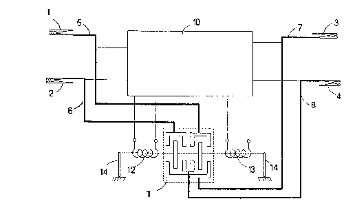
present invention, FIGS. 1 and 2 illustrate a plurality of
conventional battery terminal clamps 1-4 attached to a plurality
of corresponding booster cables 5-8, respectively. A polarity
6
controller 9 is electrically connected between the cables 5 and 7
and also between the cables 6 and 8 as best illustrated in FIG. 2.
The polarity controller 9 includes a polarity sensing and
relay control circuit 10 and a reversing relay 11. First and
second relay coils 12 and 13 are electrically connected to the
circuit 10 and cause selective activation of movable contacts in
the relay 11 to either electrically connect cable 5 to cable 7 and
cable 6 to cable 8, or cable 5 to cable 8 and cable 6 to cable 7,
depending on the polarity sensed by the circuit l0 as discussed in
further detail below. A pair of springs 1~ are graphically
depicted in FIG. 2 which cot to maintain the movable contacts of
the relay 11 in a non-contacting neutral or off position when
energizing voltage is not supplied to either of the coils 12 or 13.
The operation o~ the charging cable system can be
described in broad terms by referring to FIG. 2. Clamps 1 and 2
are connected to a charged battery or any other source of power
(not shown), while clamps 3 and 4 are connected to a battery to be
charged (also not shown). The sensing and control circuit 10
senses the polarity at cables 5 and C~ and the polarity at cables
7 and 8, and energizes the appropriate relay coil 12 or 13 so that
relay Z1 connects the positive terminal of the source to the
positive terminal of the battery to be charged and the negative
terminal of the source to the negative terminal of the battery to
be charged.
7
To explain in greater detail how the above operation is
achieved, reference is made to FIG. 3a. 15 is a full wave
rectifier which, when the system is connected to the source via
clamps 1 and 2, regardless of polarity, will produca a positive
voltage on a wire 20 with respect to a wire 21. Wires 20 and 21
form the DC supply lines for the rest of the sensing and control
circuit 10. 16 is a differential amplifier which produces no
output until a predetermined differential voltage appears at its
input terminals which are connected to cables 7 and 8. Amplifier
16 also has a tristate output, i.e., when its input differential
voltage is below a certain level, its output is floating. 17 is
another differential amplifier with the same characteristics as
amplifier 16 but with its input polarity reversed. i8 is an
electronic pulse generator which produces a pulse every few
seconds. This pulse is applied to amplifiers 16 and 17 and, during
this pulse, amplifiers 16 and 17 go into their tristate or floating
mode. 19 is a voltage sensor which senses the voltage across
supply lines 20 and 21 and produces an output signal which is
connected to pulse generator 18. When the supply voltage drops
below a certain value, sensor 19 produces a signal which disables
pulse generator 18.
In more detail, operation of the battery charging cable
system is as follows. Clamps 1 and 2 are connected to a charged
battery or a DC power source (in case of a service truck this may
8
~~J~~e'~
be a permanent connection to the truck°s batteries). Regardless
of the polarity at cables 5 and 6, full wave rectifier 15 will
provide a positive voltage on supply line 20 with respect to supply
line 21. These two supply lines power amplifiers 16 and 17 and
pulse generator 18. Before clamps 3 and 4 are connected to the
battery to be charged, the input terminals of amplifiers 16 and 17
have zero volts impressed on them and therefore, their outputs are
floating (in tristate mode), hence, coils 12 and 13 are not
energized. When clamps 3 and 4 are connected to a battery to be
charged, and if the battery to be charged has at least a small
amount of voltage across its terminals (50 to 100 millivolts for
instance) , amplifiers 16 and 17 will produce output voltages of
opposite polarity: i.e., if amplifier 16 produces a positive
voltage at its output terminal, amplifier 17 produces a negative
voltage or vice versa depending on the polarity across 'the battery
terminals (note that the two amplifiers have opposite signs at
their inputs).
Now, which relay coil will be energized depends on the
polarity of the charging source at clamps 1 and 2. To clarify the
operation further, consider the case where clamp 1 is positive,
clamp 2 is negative, clamp a is negative and clamp 4 is positive.
In this case, amplifier 16 will have a positive output and
amplifier 17 will have a negative output. Considering the polarity
at clamps 1 and 2, coil 13 will have both of its terminals at the
same positive potential and therefore it will not be energized,
9
,.-..
while coil 12 will have one of its terminals at positive voltage
(clamp 1) and its other terminal at negative voltage (output of
amplifier 17), and it will be energized. Energizing coil 12 will
cause the movable contacts of relay il to be moved to the left and
connect clamp 1 to clamp 4 via cables 5 and 8 and clamp 2 to clamp
3 via cables 6 and 7; i.e., clamp 1, which is sensed to be
positive, will connect to clamp 4, which is also sensed to be
positive; clamp 2, which is sensed to be negative, will connect to
clamp 3, which is sensed to be negative.
Now if clamp 3 is connected to the positive terminal of
a battery to be charged and clamp 4 is connected to the negative
terminal., by the same reasoning as before, coil 13 will now be
energized pulling the movable contacts of relay 11 to the right and
thus connecting clamp 1 to clamp 3 and clamp 2 to clamp 4. In
either case the two batteries will be connected correctly. It is
easy to see from the above that even if the assumed polarity of
clamps 1 and 2 is reversed, the relay will operate in such a way
as to still make the correct connections.
After disconnecting the battery being charged from the
cables, it is important to reset the system in its original state,
i.e., set the relay in its off or neutral position and thus
disconnect the output side of the cables from the input side. In
this way, if the output side is reconnected to the battery, the
system will make the right connections automatically again as
~~~~~~ ~v
before. One method of achieving this is as shown in FIG. 3a. In
particular, the pulse generator 18 and the voltage sensor 19 serve
this function and operate as follows. While charging a battery,
at normal current, the pulse generator 18 keeps interrupting the
power to the relay coils 12 or 13 by applying pulses to amplifiers
16 and 17. The interruptions are of short duration; for example, ',
percent of the on time. If clamps 3 and 4 are disconnected from
the battery being charged, at the first interruption thereafter,
the relay 11 will reset to the off position and, because there is
10 no longer voltage at clamps 3 and 4, the relay il will not be re
energized and will remain off or open circuited. When a battery
is being charged and someone tries to start the vehicle serviced
by the battery, the starter will draw a heavy current and the
voltage across the cables will drop. During this time, the voltage
sensor 19 will sense the lower voltage and prevent the pulse
generator 18 from interrupting the relay 11. This prevents the
switching of heavy currents which may cause burnout of the relay
contacts.
An alternative arrangement for resetting the system after
disconnection of a source or battery to be charged is illustrated
in FIG. 3b. A saturable magnetic core 22 encircles the cable 7 and
is employed to sense current flowing therethrough. An electronic
oscillator 22A provides oscillating current in a winding of the
core 22 which in turn generates an oscillating voltage across the
winding that is fed to an amplifier 24. The amplifier 24 produces
1~
_..\
a binary high level output voltage when the oscillating voltage at
its input is high. A two input OR gate 23 has its inputs connected
to the relay coils 12 and 13 and produces a binary high-level
output voltage when either of its inputs are high. The outputs of
the amplifier 24 and OR gate 23 are fed as inputs to a two input
AND gate 25, the output of which is connected to a relay 27 which,
when energized, disconnects one side of relay coils 12 and 13 from
the cable 5, thereby resetting the relay 11 to its neutral or off
position.
Operation of the current sensing scheme of the embodiment
illustrated in FIG. 3b is as follows. If clamps 1 and 2 are
connected to a source, there is no current in cable 7, the
oscillatory voltage across the winding of coil 22 is high, the
output of amplifier 24 is high, the output of OR gate 23 is low
(no coils are energized), the output of AND gate 25 is low since
one of its inputs is low and, therefore, coils 12 and 13 are
connected to cable 5.
The next step is to connect clamps 3 and 4 to a battery '
to be charged. Under this condition, the sensing amplifiers 16 and
17 will energize the appropriate relay coil and the relay 11 will
connect the source and the battery to be charged correctly and
current will flow through the cables including cable 7. During
this phase of operation, the oscillatory voltage across the winding
of core 22 will drop because of saturation of the core due to the
as
__,
current in cable 7. This causes the output of amplifier 24 to go
low, and the output of AND gate 25 will remain low, thus keeping
relay 27 de-energized. When clamps 3 and 4 are eventually removed
from the battery being charged, then, current in cable 7 will stop
flowing, the oscillatory voltage across the winding of core 22 will
increase to its highest output, and the output of amplifier 24 will
go high. Now the AND gate 25 has two high inputs and therefore its
output will go high and energize relay 27, thus de-energizing relay
coils 12 ar 13. When this happens, the voltage across cables 7 and
8 will drop to zero and amplifiers 16 and 17 will have zero output.
The output of the AND gate 25 will go to zero, releasing relay 27,
and thus the system is reset.
Monitoring and alarm circuits are also provided in the
embodiment shown in FIG. 3b. These include a full wave rectifier
28, amplifier 29, AND gate 30, visual alarm (light) 31 and audio
alarm 32. In general, the alarms 31 and 32 will be activated when
there is no current in the cables but, at the same time, there is
voltage across the cables 7 and 8. This condition will exist when
either amplifier 16 or 17 have an output high or the relay contacts
are fused together. Rectifier 28 rectifies the voltage across
cables 7 and 8 and its DC output is fed to differential amplifier
29. Thus amplifier 29 will have a binary high output when there
is voltage of any polarity across cables 7 and 8. AND gate 3o has
one input connected to amplifier 29 and one to amplifier 24. The
output of gate 30 operates alarms 31 and 32.
13
In the operation of the monitoring and alarm circuit, if
there is no current in cable 7, amplifier 24 has a high output.
If there is voltage across cables 7 and 8, amplifier 29 also has
a high output. Therefore, gate 30 has a high output, and alarms
31 and 32 will be activated to indicate that the relay contacts
remain closed in spite of the fact that the clamps 3 and 4 have
been disconnected from a battery to be charged, and therefore no
current is flowing through cable ?.
l0
Yet another way of resetting the system after the battery
to be charged is disconnected from the booster cables is to use a
different current sensing scheme as is illustrated in FIG. 3c. In
this scheme, the very small voltage developed across the cable is
sensed by a single differential amplifier 33. Amplifier 33 is a
high gain amplifier having its two inputs connected either across
a part of cable 7 as shown or across the whole length of cable 7
or even across a shunt (not shown). Amplifier 33 amplifies the
small voltage developed across the portion of the cable 7 which is
between its two input terminals, and produces a digital low output
regardless of the polarity at its input. The voltage out of
amplifier 33 takes the place of the voltage produced by amplifier
24 (FIG. 3b) and the operation of the scheme becomes identical to
the scheme illustrated in FIG. 3b.
S4
. '' ,~ . v ~ ;, ; . . . . '.
~. ., . ~ . .:': , . ,, ..' . , . ,w,
A still further scheme for resetting the system is shown
in FIG. 3d. Here 26 is a voltage sensor which senses and amplifies
any change of voltage in the positive direction and provides a
positive pulse to amplifiers 16 and 17 which sets them in their
tristate mode momentarily. Operation of this scheme is very
simple. When the battery being charged is disconnected, the
voltage across supply lines 20 and 21 will increase slightly
because of the unloading of the source. Amplifier 26 detects the
upward change in voltage, produces a positive pulse and de-
energizes relay coils 12 or 13, thus resetting the relay 11 to its
neutral or off position. After the duration of the pulse, the
relay will stay in its neutral or off position since there will not
be any voltage across cables 7 and 8.
A preferred embodiment of the structure of the reversing
relay 11 is illustrated in FIGS. 4a-e. In FIG. 4b, 34 and 35 are
armatures for the relay coils 12 and 13, respectively. The leaf
springs 14 are employed to connect the armature 34 to a relay base
plate 38, and the armature 35 to a relay base plate 39.
As illustrated in FIGS. 4c-e, 40 is a movable shaft on
whioh are mounted, first and second flat disc shaped contacts 41
and 42, by means of an insulator body 43 and a plurality of spring
washers 44. The insulator body 43 holds the contacts 41 and 42
apart and electrically insulates them from one another, while the
springs 44 provide resilience for the contacts 41 and 42.
3.5
A first pair of flat strip contacts 45 and 46 are
electrically connected together by a first conducting spacer 47,
and are also electrically connected to the cable 7. A second pair
of flat strip contacts 48 and 49 are electrically connected
together by a second conducting spacer 50, and are also
electrically connected to the cable 8. A third pair of flat strip
contacts 51 and 52 are connected together by a third conducting
spacer 53, and are also electrically connected to the cable 5.
Finally, a fourth pair of flat strip contacts 54 and 56 are
electrically connected together by a fourth conducting spacer 55,
and are also electrically connected to the cable 6. A plurality
of insulators 60 are employed to electrically insulate the various
contacts and spacers from one another.
In the operation of the reversing relay 11, when relay
coil 12 is energized, the magnetic field produced thereby attracts
armature 34 and the gap between armature 34 and coil 12 closes.
Movable relay contacts 41 and 42 are pushed downward via shaft 40,
so that contact 41 connects contact 48 with contact 52, thus
providing electrical connection between cable 8 and cable 5. At
the same time, contact 42 connects contact 46 with contact 54, thus
providing electrical connection between cable 7 and cable 6.
iahen relay coil 13 is energized, the magnetic field
produced thereby attracts armature 35, and the movable relay ,
~s
~~J~~~ ~
contacts 41 and 42 are pushed upward via shaft 40 so that contact
41 connects contact 45 with contact 51, thus providing electrical
connection between cable 7 and cable 5. At the same time, contact
42 connects contact 49 with contact 56, thus providing electrical
connection between cable 8 and cable 6.
Thus, given a polarity between cables 5 and 6, the
polarity between cables 7 and 8 depends on which of the relay coils
12 or 13 is energized. Note that leaf sprincT elements. 14 farce
armatures 34 and 35 against each other and when neither of the
coils 12 or 13 are energized, the movable relay contacts 41 and 42
axe centered between the various stationary contacts so 'that no
connection is made between cables 5, 6, 7, or 8. This is the
neutral or off position of the relay 11 and is an advantage when
a battery is charged from a source because if clamps 3 and 4 are
accidentally touched together before being connected to the battery
to be charged, no short circuit will occur.
Another advantage of this relay construction is that
there are no flexing wires. Most comman relays depend an flexing
wires for their operation and because of the heavy currents
involved in charging batteries, heavy gauge wires are used which
are very difficult to flex. Yet another advantage of the relay
construction illustrated in FIGS. 4a-a is that it has an inherent
mechanical advantage. The force produced by the magnetic
attraction at the coils 12 and l3 is multiplied, due to leverage,
17
~~r~~ar~
.~ i~ ~~ i~
by about a factor of 2 at the middle of the armatures 34 and 35
where the movable shaft 40 is located. Therefore, the force
pressing the various contacts together is greater for a given
current in the relay coils 12 and 13 than if the mechanical
advantage was not implemented. Finally, as can be seen best in
FIG. 4a, each of the cables 5-8 are attached to their respective
terminals on the relay 11 in such a manner that the cables are not
bent at any sharp angles. This is an important consideration since
booster cables axe typically very heavy gauge and are therefore
l0 difficult to bend.
,Although the present invention has been disclosed in
terms of preferred embodiments, it will be understood that numerous
variations and modifications could be made thereto without
departing from the spirit and scope of the invention as defined in
the following claims.
i~