Sélection de la langue

Search

Sommaire du brevet 2058309 

Énoncé de désistement de responsabilité concernant l'information provenant de tiers

Une partie des informations de ce site Web a été fournie par des sources externes. Le gouvernement du Canada n'assume aucune responsabilité concernant la précision, l'actualité ou la fiabilité des informations fournies par les sources externes. Les utilisateurs qui désirent employer cette information devraient consulter directement la source des informations. Le contenu fourni par les sources externes n'est pas assujetti aux exigences sur les langues officielles, la protection des renseignements personnels et l'accessibilité.

Disponibilité de l'Abrégé et des Revendications

L'apparition de différences dans le texte et l'image des Revendications et de l'Abrégé dépend du moment auquel le document est publié. Les textes des Revendications et de l'Abrégé sont affichés :

  • lorsque la demande peut être examinée par le public;
  • lorsque le brevet est émis (délivrance).
(12) Brevet: (11) CA 2058309
(54) Titre français: COUPLEUR-REPARTITEUR A GUIDE DE LUMIERE
(54) Titre anglais: WAVEGUIDE-TYPE COUPLER/SPLITTER
Statut: Périmé et au-delà du délai pour l’annulation
Données bibliographiques
(51) Classification internationale des brevets (CIB):
  • G02B 27/10 (2006.01)
  • G02B 06/28 (2006.01)
  • G02B 06/34 (2006.01)
(72) Inventeurs :
  • YANAGAWA, HISAHARU (Japon)
  • SHIMIZU, TAKEO (Japon)
  • NAKAMURA, SHIRO (Japon)
  • OYAMA, ISAO (Japon)
(73) Titulaires :
  • THE FURUKAWA ELECTRIC CO., LTD
(71) Demandeurs :
  • THE FURUKAWA ELECTRIC CO., LTD (Japon)
(74) Agent: SMART & BIGGAR LP
(74) Co-agent:
(45) Délivré: 2001-12-04
(22) Date de dépôt: 1991-12-23
(41) Mise à la disponibilité du public: 1992-06-28
Requête d'examen: 1998-11-26
Licence disponible: S.O.
Cédé au domaine public: S.O.
(25) Langue des documents déposés: Anglais

Traité de coopération en matière de brevets (PCT): Non

(30) Données de priorité de la demande:
Numéro de la demande Pays / territoire Date
2-407852 (Japon) 1990-12-27

Abrégés

Abrégé anglais


A 2-input/2-output directional coupler is
arranged as an element coupler/splitter for a first
stage, and 1-input/2-output coupler/splitters are used
as element coupler/splitters for a second stage and
its subsequent stages. Output ports of these element
coupler/splitters are concatenated with input ports of
other element coupler/splitters to form a 2-
input/multi-output coupler/splitter.
An optical signal can be inputted through one
input port of the first-stage 2-input/2-output
directional coupler, and an optical signal for optical
line monitoring can be inputted through the other
input port. It is unnecessary, therefore, to use an
optical wavelength division multiplexer/demultiplexer
or other optical part which conventionally is
connected at the time of optical line monitoring.

Revendications

Note : Les revendications sont présentées dans la langue officielle dans laquelle elles ont été soumises.


8
CLAIMS:
1. A waveguide-type coupler/splitter comprising:
a plurality of element coupler/splitters concatenated
to one another, input ports of said individual element
coupler/splitters being connected to output ports of other
element coupler/splitters,
said element coupler/splitter in a first stage being
a 2-input/2-output coupler/splitter, wherein said element
coupler/splitter in the first stage has a branch coupling ratio
which is wavelength-independent for light having a wavelength
falling within a predetermined range, and
each of said element coupler/splitters in a second
stage and in subsequent stages being a 1-input/2-output
coupler/splitter.
2. A waveguide-type coupler/splitter according to claim
1, wherein said first-stage element coupler/splitter has a
first slit cut in one of the input ports thereof, a filter
housed in the first slit for transmitting light with a
communication wavelength and reflecting light with a monitoring
wavelength, a second slit cut in the other input port thereof
and a filter housed in the second slit for reflecting light
with the communication wavelength and transmitting light with
the monitoring wavelength.
3. A waveguide-type coupler/splitter according to claim
1, wherein each of said element coupler/splitters in the second
stage and the subsequent stages is a Y-branch waveguide.
4. A waveguide-type coupler/splitter according to claim
1, wherein each of said element coupler/splitters in the second

9
stage and the subsequent stages is a 1-input/2-output
directional coupler having a junction at which two waveguides
for output are discontinuous with one waveguide for input.

Description

Note : Les descriptions sont présentées dans la langue officielle dans laquelle elles ont été soumises.

- 1 -
TITLE OF THE INVENTION
~AVEGUIDE-TYPE COUPLER/SPLITTER
BACKGROUND OF TIIE INVENTION
Field of the Invention
The present invention relates to waveguide-type
coupler/splitters effectively used in an optical fiber
communication system and optical sensor system, and
more particularly, to waveguide-type coupler/splitters
which need not be connected with any other optical
parts, such as an optical wavelength division _
multiplexer/demultiplexer, at the time of optical line
monitoring in these systems.
Description of the Prior Art
In an optical fiber communication system, such as
the one shown in Fig. 1, a signal transmitted from one
parent station 1 is divided into N number of signals
by means of a 1-input/N-output waveguide-type
coupler/splitter 2, and the individual signals are
distributed to N number of child stations 4z, ~2,
~ ~ ~ 4N by means of N number of fiber lines 3,., 32,
~ ~ ~ 3N, respectively.
Referring now to Figs. 2 to 7, 1-input/16-output
versions of the coupler/splitter 2 adapted to be used
in this system will be described by way of example.
A coupler/splitter A of the type shown in Fig. ~
uses, as each of its element coupler/splitters, a 1-
input/2-output Y-branch waveguide I in which two
output ports I~ and I~ are continuous with an 3.nput
port I~., as shown in Fig. 3. The input and output
ports Ia, I" and IQ of these individual element
coupler/splitters are concatenated to ane another in

- 2 -
four stages in a tournament-list style.
A coupler/splitter B of the type shown in Fig. 4
uses, as each of its element coupler/splitters, a 1-
input/2-output directional connector II formed of a 1-
input/2-output Y-branch waveguide and having a
junction IIu at which one of two waveguides is
continuous and the other is discontinuous, as shown in
Fig. 5. Input and output ports IIB, IIb and II~ of
these individual element coupler/splitters are
concatenated to one another in four stages.
A coupler/splitter C of the type shown in Fig. 6
uses, as each of its element coupler/splitters, a 1-
input/2-output directional coupler III formed of a 1-
input/3-output Y-branch waveguide and having a
junction IIId at which two waveguides are
discontinuous with another waveguide, as shown in Fig.
7. Input and output parts IIIa, IIIb and III of
these individual element coupler/splitters are
concatenated to one another in four stages.
In monitoring the optical fiber lines 3a, 32,
~ ~ ~ 3N without interrupting communication between
the parent station and the child stations 4,., 42,
~ ~ ~ 4~, in the optical communication system shown
in Fig. 1, it is necessary to connect an optical line
monitoring device (e. g., OTDR) 5, which uses light
with a monitoring wavelength ~.Z different from a
communication wavelength ~.z, as shown in Fig. 8, to
the arrowed spat (Fig. 1) of an optical path
connecting the parent station 1 and the 1-input/N=
output coupler/splitter 2, through an optical
wavelength division multiplexer/demultiplexer 6 for
synthesizing and dividing light waves with the

CA 02058309 2001-05-16
72465-34
3
wavelengths ~,1 and
Thus, when using the 1-input/N-output
coupler/split.ter 2 composed of the concatenated 1-input/2-
output element coupler/:~plitters I, II or III of the
conventional configuration described above, the interposition
of another optical part, such as the optical wavelength
division mulitiplexer/demultiplexer (~,1 # ~,2) or an optical
coupler (~,1 = ~,z) , is required in connecting the optical line
monitoring device 5 between the coupler/splitter 2 and the
parent station 1.
OBJECT AND SUMMARY OF THE INVENTION
The object of the present invention is to provide a
waveguide-type coupler/:~plitter capable of optical line
monitoring without the .interposition of any other optical part,
such as an optical wavelength division
multiplexer/demultiplexE=r or optical coupler.
In order to achieve the above object, according to
the present invention, there is provided a waveguide-type
coupler/splitter compri:~:ing: a plurality of element
coupler/splitters concatenated to one another, input ports of
said individual element coupler/splitters being connected to
output ports of other element coupler/splitters, said element
coupler/splitter in a f_L_rst stage being a 2-input/2-output
coupler/splitter, where_Ln said element coupler/splitter in the
first stage has a branch coupling ratio which is wavelength-
independent for light ha,;ring a wavelength falling within a
predetermined range, anc~ each of said element coupler/splitters
in a second stage and in subsequent stages being a 1-input/2-
output coupler/splitter.

CA 02058309 2001-05-16
72465-34
3a
In the couple:r/splitter of the present invention, the
first-stage element coupler/splitter is a 2-input/2-output
coupler/splitter, and therefore, the

input ports thereof can be used separately, one for
communication and the other for optical line
monitoring. Alternatively, the two input ports may be
used individually as a running version and as a stand-
by (spare).
BRIEF DESCRIPTION OF THE DRAWINGS
Fig. 1 is a schematic view showing an example of
an optical fiber communication system;
Fig. 2 is a schematic view showing an example of -
a conventional waveguide-type coupler/splitter;
Fig. 3 is a schematic view showing a 1-input/2-
output element coupler/splitter of the Y-branch
waveguide type used in the coupler/splitter of Fig. 2;
Fig. 4 is a schematic view showing another
example of the conventional waveguide-type
coupler/splitter;
Fig. 5 is a schematic view showing a 1-input/2-
output element coupler/splitter of the directional
connector type used in the coupler/splitter of Fig. 4;
Fig. 6 is a schematic view showing still another
example of the conventional waveguide-type
coupler/splitter;
Fig: 7 is a schematic view showing a 1-input/2-
output element coupler/splitter of the directional
connector type used in the coupler/splitter of Fig. 6;
Fig. 8 is a schematic view showing an optical
part interposed for optical line monitoring in the
optical communication system of Fig. 1;
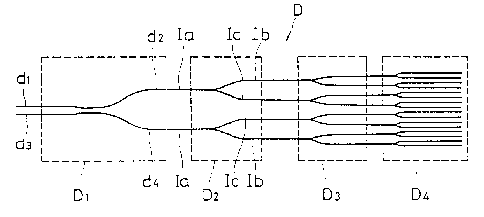
Fig. 9 is a schematic view showing a 2-input/16-
output waveguide-type coupler/splitter according to
the present invention; and

- 5 -
Fig. 10 is a schematic view showing a 2-input/2-
output element coupler/splitter of the directional
connector type arranged in a .first stage of the
coupler/splitter of the present invention.
DETAILED DESCRIPTION OF TfIE PREFERRED EMBODIMENTS
Fig. 9 is a schematic view showing a 2-input/16-
output coupler/splitter. In this coupler/splitter D,
a First-stage element coupler/splitter D~ is a 2-
input/2-output coupler/splitter, as shown in Fig. 10.
The input port Ia of the Y-branch waveguide I shown in
Fig. 3 is concatenated to each of output ports dz and
d4 of the coupler/splitter D,., thus forming a second-
stage element coupler/splitter group D2 having four
output ports. Further, the input port Ia of the Y-
branch waveguide I is concatenated to each of the
output ports Ib and I~ of each group-DZ Y-branch
waveguide, thus forming a third-stage element
coupler/splitter group D3 having eight output ports.
Likewise, the input port Ia of the Y-branch waveguide
I is concatenated to each of the output ports Ib and
I~ of each group-group D3 Y-branch waveguide, thus
forming a fourth-stage element coupler/splitter group
D4 having sixteen output ports.
After the formation of the group D4, additional
Y-branch waveguides are successively concatenated in
the same manner as aforesa9.d. If the 1-input/2-output
element coupler/splitters are connected in _~n - 1)
stages in all, the resulting coupler/splitter becomes
a ~-input/2n-output coupler/splitter.
The element coupler/splitters concatenated in the
second stage and its subsequent stages are not limited

CA 02058309 2001-05-16
72465-34
6
to the Y-branch waveguide I shown in Fig. 3, and may be of the
type II shown in Fig. 5 or the type III shown in Fig. 7 or
suitable combinations o:E these types I, II and III.
In the wavegu:ide-type coupler/splitter according to
the present invention, i~:he coupler/splitter D1 as an element
coupler/split.ter in the first stage is arranged so that a
signal with a communical_ion wavelength ~,1 is inputted through
the one input. port dl (or: d2), while a light beam for optical
line monitoring with a monitoring wavelength ~,2 is inputted
1G through the other input fort d2 (or dl).
Preferably, the coupler/splitter D1 should be one
whose branch coupling r<~tio for light having a wavelength
intermediate between the communication wavelength ~,1 and the
monitoring wavelength ~,~;is wavelength-independent, that is, a
l~ coupler/split.ter which :i;s wavelength-flattened between the
communication and monitoring wavelengths.
As an example of the coupler/splitter of this type,
there is an asymmetric Mach-Zehnder interferometer-type optical
waveguide coupler with wavelength insensitive coupling ratio by
2C KANAME JINGUJI, et al ":I:ntegrated Photonics Research" 1990
Technical Digest Series Volume 5 Conference Edition March 26 to
28 1990, Hilton Head, North Carolina (WINO) Topical Meeting on
Integrated Photonic Research.
Preferably, the coupler/splitter D1 is arranged so
2~~ that a slit i.s cut in the one input port dl, for example, and a
filter which transmits :Light with the communication wavelength
1 and reflects light wi.t:h the monitoring wavelength ~,2 is
housed in the slit, and ,at the same time, another slit is cut

CA 02058309 2001-05-16
72465-34
6a
in the other input port~~ d2, and a filter which reflects light
with the communication wavelength ~1 and transmits light with
the monitoring wavelength ~

2(~~83~~
Thus, according to the present waveguide-type
coupler/splitter, the element coupler/splitters used
are equal in number to the ones used in the
conventional coupler/splitter. Since the first-stage
element coupler/splitter is a 2-input/2-output
coupler/splitter, however, one of its input ports can
be used for optical line monitoring, so that it is
unnecessary to use an exclusive optical part for
optical line monitoring which conventionally is
essential.

Dessin représentatif
Une figure unique qui représente un dessin illustrant l'invention.
États administratifs

2024-08-01 : Dans le cadre de la transition vers les Brevets de nouvelle génération (BNG), la base de données sur les brevets canadiens (BDBC) contient désormais un Historique d'événement plus détaillé, qui reproduit le Journal des événements de notre nouvelle solution interne.

Veuillez noter que les événements débutant par « Inactive : » se réfèrent à des événements qui ne sont plus utilisés dans notre nouvelle solution interne.

Pour une meilleure compréhension de l'état de la demande ou brevet qui figure sur cette page, la rubrique Mise en garde , et les descriptions de Brevet , Historique d'événement , Taxes périodiques et Historique des paiements devraient être consultées.

Historique d'événement

Description Date
Inactive : CIB de MCD 2006-03-11
Le délai pour l'annulation est expiré 2003-12-23
Lettre envoyée 2002-12-23
Accordé par délivrance 2001-12-04
Inactive : Page couverture publiée 2001-12-03
Préoctroi 2001-08-27
Inactive : Taxe finale reçue 2001-08-27
Un avis d'acceptation est envoyé 2001-06-18
Lettre envoyée 2001-06-18
Modification reçue - modification volontaire 2001-06-18
Inactive : Approuvée aux fins d'acceptation (AFA) 2001-06-06
Modification reçue - modification volontaire 2001-05-16
Inactive : Dem. de l'examinateur par.30(2) Règles 2000-11-27
Lettre envoyée 1998-12-21
Inactive : Renseign. sur l'état - Complets dès date d'ent. journ. 1998-12-21
Inactive : Dem. traitée sur TS dès date d'ent. journal 1998-12-21
Modification reçue - modification volontaire 1998-12-16
Exigences pour une requête d'examen - jugée conforme 1998-11-26
Toutes les exigences pour l'examen - jugée conforme 1998-11-26
Demande publiée (accessible au public) 1992-06-28

Historique d'abandonnement

Il n'y a pas d'historique d'abandonnement

Taxes périodiques

Le dernier paiement a été reçu le 2000-12-01

Avis : Si le paiement en totalité n'a pas été reçu au plus tard à la date indiquée, une taxe supplémentaire peut être imposée, soit une des taxes suivantes :

  • taxe de rétablissement ;
  • taxe pour paiement en souffrance ; ou
  • taxe additionnelle pour le renversement d'une péremption réputée.

Les taxes sur les brevets sont ajustées au 1er janvier de chaque année. Les montants ci-dessus sont les montants actuels s'ils sont reçus au plus tard le 31 décembre de l'année en cours.
Veuillez vous référer à la page web des taxes sur les brevets de l'OPIC pour voir tous les montants actuels des taxes.

Historique des taxes

Type de taxes Anniversaire Échéance Date payée
TM (demande, 6e anniv.) - générale 06 1997-12-23 1997-12-01
Requête d'examen - générale 1998-11-26
TM (demande, 7e anniv.) - générale 07 1998-12-23 1998-12-02
TM (demande, 8e anniv.) - générale 08 1999-12-23 1999-12-01
TM (demande, 9e anniv.) - générale 09 2000-12-25 2000-12-01
Taxe finale - générale 2001-08-27
TM (brevet, 10e anniv.) - générale 2001-12-24 2001-12-03
Titulaires au dossier

Les titulaires actuels et antérieures au dossier sont affichés en ordre alphabétique.

Titulaires actuels au dossier
THE FURUKAWA ELECTRIC CO., LTD
Titulaires antérieures au dossier
HISAHARU YANAGAWA
ISAO OYAMA
SHIRO NAKAMURA
TAKEO SHIMIZU
Les propriétaires antérieurs qui ne figurent pas dans la liste des « Propriétaires au dossier » apparaîtront dans d'autres documents au dossier.
Documents

Pour visionner les fichiers sélectionnés, entrer le code reCAPTCHA :


Pour visualiser une image, cliquer sur un lien dans la colonne description du document (Temporairement non-disponible). Pour télécharger l'image (les images), cliquer l'une ou plusieurs cases à cocher dans la première colonne et ensuite cliquer sur le bouton "Télécharger sélection en format PDF (archive Zip)" ou le bouton "Télécharger sélection (en un fichier PDF fusionné)".

Liste des documents de brevet publiés et non publiés sur la BDBC .

Si vous avez des difficultés à accéder au contenu, veuillez communiquer avec le Centre de services à la clientèle au 1-866-997-1936, ou envoyer un courriel au Centre de service à la clientèle de l'OPIC.

({010=Tous les documents, 020=Au moment du dépôt, 030=Au moment de la mise à la disponibilité du public, 040=À la délivrance, 050=Examen, 060=Correspondance reçue, 070=Divers, 080=Correspondance envoyée, 090=Paiement})


Description du
Document 
Date
(aaaa-mm-jj) 
Nombre de pages   Taille de l'image (Ko) 
Dessins 2001-05-15 3 50
Description 2001-05-15 9 245
Revendications 2001-05-15 2 47
Revendications 1994-03-29 2 41
Dessins 1994-03-29 3 46
Description 1994-03-29 7 222
Abrégé 1994-03-29 1 21
Dessin représentatif 1999-07-21 1 3
Revendications 2001-06-17 2 47
Dessin représentatif 2001-10-30 1 8
Rappel - requête d'examen 1998-08-24 1 129
Accusé de réception de la requête d'examen 1998-12-20 1 177
Avis du commissaire - Demande jugée acceptable 2001-06-17 1 165
Avis concernant la taxe de maintien 2003-01-19 1 174
Correspondance 2001-08-26 1 40
Taxes 1996-12-01 1 76
Taxes 1995-11-23 1 73
Taxes 1994-11-15 1 43
Taxes 1993-10-27 1 27