Note : Les descriptions sont présentées dans la langue officielle dans laquelle elles ont été soumises.
~--~,
_1_
APPARATUS AND METHOD FOR DETECTING SEISMIC WAVES IN
A BOREHOLE USING MULTIPLE CLAMPING DETECTOR UNITS
Field of the Invention
The present invention relates to geophysical exploration
apparatus and methods.
Back~cround of the Invention
Downhole detectors of seismic waves are well known in the
art. A typical prior art tool includes the following elements
in a single housings sensors, such as geophones, that convert ,
mechanical vibrations into electrical signals; associated
electronics; a clamp that fastens the tool to the borehole wall;
and a motor that actuates the clamp. These downhole detectors
are large with lengths as long as 6 feet and weights as much as
i60 pounds. They often have the capacity to clamp in holes with
diameters ranging from S inches to over a foot.
During acquisition of seismic data, the detector is lowered
into a well and clamped at a desired depth. Seismic waves are
created by conventional sources and detected by the tool. The
tool is then lowered to a new depth, and the process is
25, repeated. In the most common configuration, data can be ___
recorded by only one detector unit at one depth at a time.
Recently, new tools have been devised which can record data
~1
-2- i~~'~~,a~x~
simultaneously from several detectors locked at different depths
as disclosed in European Patent Application 0210925. This prior
art tool comprises a seismic detector and a magnetic clamp in an
open cradle carrier which can be secured to a cable linking
several such devices into an array. The size of. the detectors
is still a limiting factor on detector spacing, however.
The large size of prior art detectors also limits the
frequencies of the seismic signals that can be recorded. Prior
art downhole detectors are limited by internal mechanical
resonances of the tool and by the force with which the tool is
clamped to the borehole wall. Resanances caused by the flexing
of a tool body can interfere with the recording of the seismic
signals. The larger the tool, the lower the resonant
frequencies, and the greater the interference. With a poor
clamp; the detector will follow the motion of the borehole wall
for low frequencies; but will not couple to the wall at higher
frequencies. It is well known that better coupling resulting in
detection of higher frequencies is achieved with a greater
clamping force-to-weight ratio for the tool. Typical frequency
detection limits for prior art geophones are 200 to 300 Hertz.
There are a number of applications, such as that disclosed
in U:S: Patent 4,214,226 to Narasimhan et ~1., which require
25, high-frequency data (1000 Hz) recorded at many different depths
in the well. Prior art tools are inadequate to record the
higher frequencies for the reasons discussed above.
_..
-3-
Furthermore, to record this data in a minimal period of time, it
is important that data be simultaneously recorded at a number of
depths by multiple detectors in the well. There is also an
application disclosed in U.S. Serial Number 430,513 to Krohn
which requires multiple detectors spaced at two-foot separations
in the well. The prior art tools are too long to be spaced two
feet apart. These applications involve operations in uniform
wellbores that are often cased, however. Thus, the capacity to
record data at a large range of borehole diameters with a single
tool configuration is not required.
Summary of the Invention
In the practice of one embodiment of the present invention,
small, light-weight,~fle~cibly connected clamping detector units
are clamped to a wellbore with a large force. The small size
and weight of each detector unit is achieved by removing
apparatus that operates,the clamp from the unit. A high
farce-to-weight ratio can then be obtained by use of
hydraulically actuated locking arms located on the detector
units. The high force-to-weight ratio allows the detector uni
to press tightly against a wellbore and thus overcome the
problems of prior art clamping detector units wherein high
frequency signals are not recordable because of poorly clamped
25, detector units. Furthermore, the small size of the detector
units allows apaciag distances as short as two feet to be
achieved, thus overcoming another problem of prior art tools.
3w
.~.
-4-
One embodiment of the present invention is directed to an
apparatus having the following principle features for detecting
seismic waves in a borehole: an hydraulic pressure source; a
plurality of small, light-weight, flexibly connected clamping
detector units having hydraulically actuated clamps; conduit
means connecting the hydraulic pressure generating source to
said detector units so that the detector units may be
hydraulically clamped to a wellbore with a large force by
activation of the clamps; and means for conditioning signals
from the detectors and transmitting them to the surface of the
borehole.
A preferred embodiment of the present invention is an .
apparatus for detecting seismic waves comprising a downhole
15, hydraulic pump; a plurality of small, light-weight, flexibly
connected clamping detector units wherein each detector unit
comprises at least one geophone enclosed in a light-weight
housing; an arm moveable radially outward to contact a borehole
wall; a piston unit cooperating with said arm that converts
hydraulic pressure to mechanical motion to move the arm; conduit
means connecting the hydraulic pump to the detector units so
that the detector units may be hydraulically clamped to a
borehole with a large force by activation of tha locking arms;
and a digitizer connected to the geophones by a plurality of
25, wires. The digitized signal may then be transmitted up a
standard wire line to the surface.
Brief Description of the Drawings
For a better understanding of the present invention,
reference may be had to the drawings in which:
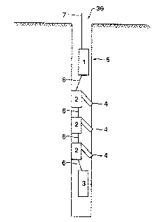
FIGURE 1 is a schematic illustration showing an embodiment
of the invention in use in a wellbore.
FIGURE 2 is a cross sectional view of an embodiment of the
clamping detector unit of the present invention.
FIGURE 3 is a pictorial sectional view of a clamping
detector unit of the present invention taken along line A-A of
' FIGURE 2:
FIGURE 4 is a pictorial sectional va.ew of a clamping
detector unit of the present invention taken along line B-B of
FIGURE 2.
FIGURE 5 is a schematic illustration of the clamping
detector unit of the present invention clamped to a wellbore.
FIGURE 6 is a top view of FTGURE 5 looking down the wellbore.
25, FIGURE 7 is a plot of vertical motion recorded'with a prior
art tool.
FIGURE 8 is a plot of the amplitude spectrum for the data
shown in FIGURE 7.
FIGURE 9 is a plot of vertical motion recorded with the
instrument of the present invention.
FIGURE 10 is a plot of the amplitude spectrum for the data
shown in FIGURE 9.
These drawings are not intended to in any way define the
present invention, but are provided solely for the purpose of
illustrating certain preferred embodiments and applications of
the present invention.
Description of the Preferred Embodiment
The components of a downhole tool 30 of the present
invention are shown in FIGURE 1. The various components of a
preferred embodiment of the tool include a digitizing and
electronics pod or digitizer 1, a number of clamping detector
units 2, and a downhole hydraulic pump 3. The various
components may be arranged in different orders. Digitizer 1 may
be used as a means for conditioning signals from detector
units 2. Detector units 2 each comprise at least one geophone
25, enclosed in a light-weight housing. Each detector unit 2
includes an arm 4 which presses the unit against a borehole
wall 5. Hydraulic pump 3 supplies hydraulic pressure to ~~
5:~.
activate arms 4 of detector units 2. Flexible cables b located
between each of the detector units 2 carry a stress member,
electrical wires for each of the geophones and a single
hydraulic hose. Because the cable is not rigid, signals cannot
be mechanically passed between clamping units 2 and interference
with the signals is thereby avoided. The top of the digitizer
fastens to a standard wixeline 7 for communication to the
surface.
In another embodiment of the invention, hydraulic pressure
may be generated at the surface and transferred to the clamping
detector units by a custom cable 7 running from the surface to
the bottom of the tool, that incorporates a hydraulic line in
addition to electrical wires. Alternately, a hydraulic line may
be run separately from the standard wireline 7. Care must be
taken to purge the hydraulic line to remove all air. The line
is connected to a pump at the surface. Pressure exerted by the
pip may be conveyed downhole by the hydraulic line to activate
the clamps 4 thereby clamping ,the detector units to the
we7.lbore. This line must be able to withstand the differential
pressure between the top and the bottom of the well.
Consequently, this method is generally limited to shallow depths
of less than 2000 feet.
25, In still another embodiment of the invention, means for
conditioning signals from the detector units may comprise a
special line instead of a digitization unit. The line may "
~,
~~'.'~~~n~~
comprise a stress member to support the tool, a pair of wires
for each detector to send electrical signals from the detector
to the surface, and wires to supply power to downhole
electronics. The signals received at the surface are digitized
and stored using conventional methods. If more than three
detectors are used, the line may need to be specially made
because standard wirelines contain only seven conductors.
Crossections of an individual clamping detector unit 2 are
shown in FIGURES 2-4. The housing 8 of detector unit 2 is
preferably made out of titanium or other light-weight material.
End gieces 9 and 10 of detector unit 2 contain electrical
connectors lI and hydraulic connectors 12: A port 13 is cut
through the body of detector unit 2 to pass the hydraulic
pressure to the other units via the hydraulic hose. A similar
port 31 located out of the plane of the drawing acts as a
passageway for the electrical wires. Connector 11 is a stress
terminated bulkhead connector commonly available in the
industry. An alternative method of connecting electrical wire s
to the individual clamping units involves running the electrical
wires through port 31 without terminating the wires. The tool
and the cable surrounding the wires are flooded with oil, and
the stress members of the cables are fastened to the tool end
pieces. '
25,
t~
-9-
A piston. 14 is used to pull a rack 15 containing teeth 26.
The teeth 26 mesh with teeth 27 on arm 16 that opens against the
borehole wall. Rack supporting bearings 34 give support to
rack 15 and allow rack movement upon application of hydraulic
pressure in piston 14. The open position 17 is shown in
FIGURE 3. The length of arm 16 can be varied to accommodate
borehole diameter. A cross-port l8 admits hydraulic fluid to
create pressure on piston 14 thzough port 13. As pressure is
created on piston 14, the piston moves downward displacing fluid
from piston cavity 32 through bladder port 33 and into
equalization means or expanding bladder 20. Bladder 20 is used
to equalize pressure in the piston cavity 32 with borehole
pressure at the depth of the individual unit. Because o~ the
bladder, a second hydraulic return line to the pump is not
needed to relieve pressure caused by the fluid displaced from
piston cavity 32. A spring 19, attached between piston 14 and
the lower end of piston cavity 32, may be used to retract arm 16
when pressure on piston 14 is released. A shear pin 21 may be
present to allow arm 16 to collapse upon exertion of upward .
force if the unit is required ko be pulled out of the hole. The
entire piston and rack assembly can be removed from the body of
the tool in one part for repair by removing end piece 10 arid
then moving arm 16 perpendicular to unit'30 so that arm 16
disengages.
~ ,
~C.'~~ ~~
-lo-
Also shown in FIGURE 2 is a geophone holder 22 containing
three geophones 23. Geophones 23 are commercially available
from 0yo Geospace. Accelorometers may also be used in place of
geophones 23. Geophones 23 are oriented in three different
orthogonal directions: Each geophone 23 may be fastened into
holder 22 with a set screw, and holder 22 may be screwed into
housing $ of detector unit 2.
In order to couple geophone holder 22 to a borehole to sense
motion of the wall of borehole perpendicular to arm 16,
conventional standoffs hor3.zontally offset from arm l6 may be
used to contact the borehole wall as shown in FIGURES 5 and 6.
Four standoffs.24, two of which are not shown, may be attached
to housing 8 of detector unit 2. Pairs of standoffs 24 are
located at the top and bottom of detector'unit 2; and
standoffs 24 in each pair may be located at angles of 45 to 60
degrees from the plane containing arm 16. Standoffs 24 may
contain a raised rounded foot 25 which contacts borehole wall 5
and which allows the unit 2 to rotate in the process of
extending arm 16.
In the practice of an embodiment of the present invention,
components 1, 2, and 3 are first assembled using connecting
cables'6. The assembly may be attached to a standard wireline 7
25, and lowered into a well to a preselected depth. Signals are
sent from wireline 7, through cables 6 to hydraulic pump 3 to
activate the application of pressure to the hydraulic line~~ "
-11- iG~~f°~~,~:~~c~
connecting pump 3 with clamping detector units 2. At each
clamping unit 2, the increased pressure on the piston 14 at
crossport 18 causes the arm to open and to apply a large force
on the borehole wall. The force against the borehole wall will
match the differential pressure between the working side of the
piston and the piston cavity that is equalized to the borehole
pressure by expanding bladder 20. After units 2 are clamped, a
seismic source is activated, and a trigger is sent to the
digitization unit to begin recording signals from the
geophonea. The digitized records may then be transferred in
sequence up wireline 7 to a computer system at the surface for
evaluation and storage. Additional seismic recordings can then
be made using the same depth location of the tool. To move the
tool, a signal maybe sent to reverse the operation of the
hydraulic pump. The negative differential pressure at
pistons l4 in each clamping unit 2 and at springs 19 causes the
arm to retract. The tool can be then moved to a new location
and clamped, or it can be removed from the borehole.
In another aspect of this invention, a method is provided
comprising clamping multiple light weight detector units in a
borehole with a force-to-weight ratio greater than 8, more
preferably greater than 10; activating a seismic source; and
recording signals caused by such seismic source up to about 1000
Hertz. The clamping multiple light weight detector units may be
clamped at depths from about 2 to about 25 feet apart and, more
preferably, from depths from about 2 to about 5 feet apart. ~~
12
One of the primary advantages of the present invention over
the prior art is that each clamping detector unit is small and
light-weight. This is achieved because the hydraulic pressure
generating source has been removed from the detector unit
housing. Because the detector units are small and light-weight,
a plurality of detector units may be strung in a wellbore and
positioned as close as from about 2 to about 50 feet apart from
each other, and preferably positioned from between 2 to 25 feet
apart. It is possible, with this inventive tool, to position
the detectors from about 2 to about 5 feet apart. This allows
recordings of signals from different depths simultaneously.
Also because of the light weight of the detector units, a high
clamp force-to-weight ratio exists allowing the unit to be held
more securely to the wellbore than with prior art clamping
units. Force-to-weight ratios of greater than about S, and
preferably greater than about 10 may be achieved by use of the
present invention. This result allows the recording of higher
frequency signals without interference from vibration of the
detector unit.
Vertical motion recorded with a commercially available tool
(SIE Geosource SWC-3C) is shown in FIGURE 7.. The tool was
locked at a depth of 400 feet in a first well. A small dynamite
charge was exploded at a depth of 200 feet in a second well
25~ approximately 250 feet from the fixst well. The data is ringy,
or not well defined, and the ringy nature of the signal obscures
multiple events. The amplitude spectrum for the data shown in
-13-
Figure 7 is displayed in Figure 8. The spectrum shows a large
amplitude peak at 300 Hertz that represents a coupling
resonance. The data above 300 Hertz are not usable because of
uncertainties in the phase of the data after a resonance.
Vertical motion recorded with a tool having embodiments the
present invention is shown in FIGURE 9. The detector unit
weighed about 14 pounds arid was clamped with a force of about
200 pounds. The recording configuration is the same as
described above. 'The data shows clean pulses without ringing.
Furthermore, the arrival of a second event can be identified.
There are no large amplitude peaks in the amplitude spectrum as
shown in Figure 10, and the amplitude is relatively flat up to
800 Hertz. The output of the dynamite source was found to
I5 decrease at frequencies above 800 Hertz during these tests9
however, lab measurements show that data can be used up to 1000
Hertz.
The preferred embodiments of the present invention have been
described above. It should be understood that the foregoing
description is intended only to illustrate certain preferred
embodiments of the invention and does not intend to define the
invention in any way. Other embodiments of the invention can be
employed without departing from the full scope of the~invention
as set forth in the appendage claims.