Note : Les descriptions sont présentées dans la langue officielle dans laquelle elles ont été soumises.
2C?59~9
23792-105
8ACKGROUND OF THE INVENTION
The present invention relates to a compound needle,
particularly for use in a knitting machine.
Such a compound needle is disposed for longitudinal
displacement in an associated gulde groove of a needle bed of
the machine and includes a needle member provided with a
head, and a closing element which cooperates with the head
and is mounted 80 as to be longitudinally displaceable
relatlve to the head. The closing element includes a shank
which 18 provided with a beard and at least one control
butt. A laterally acting brake spring is associated with
the clos1ng element and provides lateral guidance af the
closing element ln the vlcinlty of the brake spring.
In a prior art compound transfer needle of this type, a
one-part (unitary) closlng element provlded, rearward of
its control butt, with a so-called back shank, is disposed
between two narrow spring tongues that form the brake spring.
2C~5~
These two spring tongues are parts of a shaped sheet
metal component that also includes an approximately U-shaped
yoke member connecting the two spring tongues with one
another at one end. The yoke member is placed on the shank
of the closing element and is fixed thereto by appropriate
bending of its free ends. To prevent axial displacement of
the sheet metal component relative to the closing element,
the shank is provided with a small butt which is spaced from
the control butt, and the component is mounted with the yoke
member between the two butts, which act as axial stops.
Under certain conditions of use, it would be desirable
to have better lateral guidance for the closing element in
the associated groove of the needle bed of the machine in
the region of the brake spring. However, for the compound
needle of the prlor art, this would require adjustments to be
made on the closing element at the two spring tongues when
the sheet metal component is installed.
SUMMARY OF THE INVENTION
It is therefore an object of the present invention to
alleviate this problem and provide a compound needle, par-
ticularly a compound transfer needle, with which improved
guldance of the closing element in the region of the brake
spring can be realized in a relatively simple manner.
-- 3 --
2C!59~9
The above object is accomplished according to the
present invention in that a compound needle is provided which
includes a needle member and a closing element, wherein the
closing element is formed from two parts which are connected
end-to-end. The first part of the closing element includes a
shank, a beard on the shank and a coupling means on an end
reglon of the shank remote from the beard. The second part
includes a control butt, a laterally acting brake spring
means, and a receiving means which receives at least the end
region of the shank of the first part. The two parts are
undetachably and rigidly connected with one another in a
region of the coupling means.
With thls two-part configuration of the closing element,
the second part, inclùding the brake spring means, can be
deslgned lndependently of the flrst part so as to realize
optimum guidance characteristlcs in the respectlve groove of
the needle bed of the machlne. In partlcular, the second
part can be made very stable and can be provlded wlth good
lateral guidance ln spite of the llmited thicknesses of the
closing element and needle member.
In a preferred embodiment, the receiving means includes
a longltudinal groove lnto whlch the end reglon of the shank
of the flrst part ls fltted. Thls groove ensures accurate
lateral guidance of the shank where lt ls connected wlth the
2C'S9~9
second part. Moreover, the second part of the closing
element can be configured to meet conditions determined by
the mode of operation of the machine and the configuration o
its needle bed. For example, the second part may include at
least one shank or shank portion on which the control butt is
disposed. Alternatively, or in addition, the second part may
include a back shank following the control butt.
Advisably, in the embodiment including the above-
mentioned longitudinal groove, the groove opens at one end
into a first recess which is provided in the second part and
which, in turn, opens toward the top or the bottom of the
second part.
It has also been found to be advantageous for the
coupling means to include an anchoring butt disposed on the
end region of the shank of the first part. This anchoring
butt is fitted into a correspondingly shaped second recess
in the second part which starts at the longitudinal groove
and thus substantially increases the stability of the
connectlon. The longitudinal groove and the second recess
may be formed in a section of the second part which has been
shaped to form a housing. The housing section may also
support the control butt.
In the region of the second recess and/or the region of
the longitudinal groove, the second part may be provided with
2C'59~9
one or more openings that lead laterally into the second
recess and/or the longitudinal groove. Such an opening may
facilitate the establishment of a connection between the two
parts of the closing element. The two parts may be
undetachably connected with one another in a region adjacent
to the edges of the opening. For example, the anchoring butt
and the second part may be wedged, welded or soldered
together in this region. If necessary, to improve the
connection, the anchoring butt also may be provided with
undercuts, projections or other means to produce a form-
locking connection with the second part.
The closing element of the compound needle according to
the invention permits a very simple configuration of the
brake spring means which, in a preferred embodiment, includes
at least one lateral friction bend at the shank portion or
back shank of the second part. For this purpose, the shank
portion or back shank includes, in the region of this
frlction bend, a laterally disposed section of reduced
thickness.
Moreover, it is of particular advantage for the second
part to have a greater thickness than the first part, at
least along a length portion. Often it may be advisable for
the second part to have a thickness which, at least along a
length portion, corresponds approximately to the thickness of
2~59~29
the needle member. In this way, it is possible to ensure
without additional measures a substantially rotation-safe
guidance of the closing element in the associated guide
groove of the needle bed.
The first part of the closing element, including the
beard, may be punched, or cut out of an appropriate steel
band using a precision cutting tool. The second part of the
closing element may also be produced using a precision
cutting tool that cuts the entire element. Alternatively,
the second part may be produced by precision casting. In any
case, an escape of the closing element, occasionally caused
in the prior art by a lack of proper guidance of the brake
spring in the guide groove of a needle cylinder during the
loop-forming phase, is substantially eliminated by the
present invention. Moreover, the friction force generated by
the brake spring means in the compound needle of the
lnvention can be set precisely without ma~or effort.
The brake spring means may also be formed by the second
part itself by connecting the shank of the first part with
the second part so as to pro;ect from the second part such
that longitudinal planes of symmetry of this shank and the
second part laterally enclose an obtuse angle other than
180.
Zt'59~29
BRIEF DESCRIPTION OF THE DRAWINGS
Fig. 1 is a side elevational view of a compound transer
needle according to the invention.
Fig. 2 is a top plan view of the compound transfer
needle of Fig. 1.
Fig. 3 is a side elevational view of the needle element
of the compound transfer needle of Fig. 1.
Fig. 4 is a side elevational view of the first part of
the closing element of the compound transfer needle of Fig.
10 1.
Fig. 5 is an enlarged side elevational view of the
seGond part of the closing element of the compound transfer
needle of Fig. 1.
~, Fig. 6 is a sectional view along line VI-VI of Fig. 5.
Flg. 7 ls a top plan view of Fig. 5.
Flg. 8 18 a top plan view corresponding to Fig. 7, but
8howing a modified embodiment of the second part of Fig. 5.
Fig. 9 is a partial enlarged sectional side elevational
vlew of the closing element of the compound transfer needle
of Fig. 1, illustrating the point of connection between the
two parts of the closing element.
Fig. 10 is a sectional view along line X-X of Fig. 9.
2~59~9 23792-105
Fig. 11 is a side elevational view of the end portion
of the first part of the closing element of Fig. 9 including the
anchoring butt.
Fig. 12 is a plan view of an alternative embodiment.
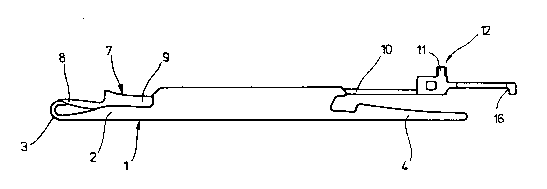
The compound transfer needle shown in Figs. 1 and 2
includes a flat needle member 1 which is provided at one end
with a head 2 having a needle hook 3, and which is provided at
the other end with a back shank 4 forming a friction bend at 5
as shown in Fig. 2. On one broadside of needle member 1, in the
region of the head 2, a draw-in spring 6 is disposed as is known
per se.
A closing element 7 is received for longitudinal
displacement in a groove la defined by the cross-sectionally
U-shaped needle member 1. One end of the closing element 7 has
a beard 8 which cooperates with the needle hook 3 in the manner
shown in Fig. 1. At the other end of the closing element 7 is
a control butt 11 followed by a back shank 16.
The closing element 7 is made of two parts. A first
part 9 includes the beard 8 and the shank 10 on which the beard
is formed, as shown in Fig. 4. A second part 12 which includes
the control butt 11 and the back shank 16, is shown in three
variations in Figs. 5-8 and 12. The two parts 9 and
2~S9~Z9
12 of the closing element 7 are undetachably and rigidly
connected with one another.
To effect such a connection, the upper face of the
first part 9 is provided with a coupling means, preferably an
anchoring butt 13, arranged at a short distance from the free
rear end 14 of the shank 10. A front end of the second part
12 is shaped to form a receiving means for the coupling
means. In this embodiment, the receiving means is a
rectangular housing section 15 to whose upper face the
control butt 11 is shaped and which is followed by the back
shank 16. In the housing section 15, a symmetrical
longitudinal groove 17 is provided which opens downward as
shown in Fig. 10 and is symmetrical with the longitudinal
center plane 7A of the closing element 7. The groove 17
extends rearwardly into a recess 18 in the back shank 16.
The opening of the recess 18 is oriented downward in Fig. 9
toward the bottom of the second part 12 and is delimited at
the end of back shank 16 by a guide member 19. The housing
sectlon 15 and the guide member 19 both lie on a common plane
20 containing the bottom face of the shank 10, as shown by a
dashed line in Fig. 9.
A recess 21 having an essentially rectangular cross
section (Fig. 6) is formed in the housing section 15 starting
at the top of the longitudinal groove 17. The recess 21
-- 10 --
2C'59~29
opens laterally toward the two parallel, opposite, laterally
disposed broadsides 40 of the housing section 15. The
opening edges of the recess 21 are designated at 22 (Fig. 5).
The recess 21 and its opening edges 22 are essentially
rectangular or square. In the rearward wall of the recess
21, ad~acent to the longitudinal groove 17 and approximately
below the control butt 11, the recess 21 is provided with a
widened portion 23 which also opens laterally into the
broadsides 40.
The two parts 9 and 12 of the closing element 7 are
produced separately, for example by precision cutting, and
are ~oined in the manner shown in Fig. 9. For this purpose,
the rear end portion lOA of the shank 10 on which the
anahoring butt 13 ls provided is inserted in a transitional
or press fit into the longitudinal groove 17. The groove 17
has parallel sides with approprlate tolerance to receive the
shank rear portlon lOA, with the anchoring butt 13 being
pressed into the recess 21 in a corresponding fit.
As is evident from Figs. 9 and 10, when the parts 9, 12
of the closing element 7 are connected, the bottom face lOB
of the shank 10 lies in the plane 20; that is, it is flush
with the bottom face of the housing seotion 15.
As is shown in Fig. 11, the front face 13A of the
anchoring butt 13 is given undercuts at 24 and 25, and such
2C~59~9
an undercut also may be provided on its rear face 13B at 26;
if necessary, these undercuts could also have a different
shape. In order to realize the undetachable connection
between the two parts 9 and 12, the housing section 15 of the
second part 12 is wedged together with the inserted anchoring
butt 13 inside the opening edges 22. As is illustrated in
Fig. 9, the material of the housing section 15 is displaced
as a result of the wedging to produce a form-locking connec-
tion between the two parts in the region of the undercuts 24
and 25. At the same time, the longitudinal groove 17 ensures
proper mutual alignment of the two parts 9 and 12 during
installation.
Instead of wedging the anchoring butt 13 together with
the houslng sectlon 15, the connection of the anchoring butt
13 with the houslng sectlon 15 could be effected, for
example, by welding or soldering them together ad~acent to
the edges 22.
The housing section 15 has a closed, cage-like
configuratlon which is accessible from the bottom through the
longitudlnal groove 17. By virtue of such a configuration, a
high wedging force can be applied to the housing section 15
wlthout distorting its shape. Thus, a highly stressable,
undetachable connection between the two parts 9 and 12 can be
ensured.
- 12 -
2~`59~9
The second part 12, at least in the housing section 15,
is delimited by parallel sides, and its thickness is greater
than that of the shank 10 of the first part 9 and corresponds
to the thickness of the needle member l. This results in
laterally disposed running or guide faces of the second part
12 -- and thus of the rear portion of the closing element 7
-- which ensure proper guidance of the closing element 7 in
the guide groove of the needle bed and preven~ twisting of
the closing element 7 during the loop-forming phase of use.
The second part 12 is also provided with a brake spring
means which, in the embodiment according to Figs. 5-7, is a
lateral friction bend 27 formed by a laterally bent portion
of the back shank 16. An elongated recess 28 is formed on
one broadside 42 of the back shank 16. This results in the
back shank 16 having a laterally disposed section of reduced
thickness in the region of the friction bend 27 and thus a
corresponding improvement of the resiliency characteristics
of the back shank 16 at this laterally bent portion is
achieved.
In the alternative embodiment according to Fig. 8, the
second part 12 is defined by parallel sides over its entire
length, and the longitudinal groove 17 is provided in the
houslng section 15 at a corre8pondingly oblique orientation.
The lateral frictlon bend is elther displaced into the shank
- 13 -
2C~59~7s2 10s
10 of the first part 9 whlch i~ correspondingly angled
at the locatlon of coupling, or the longitudinal groove 17 is
provided in the housing portion 15 at a correspondingly
obllque orientatlon. Thls results ln an arrangement ln whlch
S the longitudlnal plane of symmetry of the shank 10 of the
flrst part, pro~ecting from the second part 12 and the lon-
gltudinal plane of symmetry of the second part 12 enclose an
obtuse angle 30 whlch is sllghtly less than 180~.
In a further alternatlve embodlment, lllustrated in Fig.
12, the lateral frictlon bend ls dlsplaced lnto the shank 10
of the flrst part 9, which is correspondingly angled at the
axls 29 near lts point of connectlon to the second part 12.
This results ln an arrangement in whlch, slmllarly to the
embodlment of Flg. 8, the longltudlnal plane of symmetry of
the portlon of the shank 10 forward of the axis 29, and the
longltudlnal place of symmetry of the remalnder of the shank
10 and the second part 12, enclose an obtuse angle 32 whlch
18 sllghtly less than 180-.
It 18 to be understood that whlle the preferred
embodlments of the lnventlon were descrlbed as forming part
of a compound transfer needle, the.lnventlon may flnd
appllcatlon ln other types of compound needles as well.
- 14 -
' , ' ' ' '
2C~5~9
The invention now being fully described, it will be
apparent to one of ordinary skill in the art that any changes
and modifications can be made thereto without departing from
the spirit or scope of the invention as set forth herein.