Note : Les descriptions sont présentées dans la langue officielle dans laquelle elles ont été soumises.
DEVICE FOR H~NDL[NG DOWN--~IOLE~, PIPES
FIEL,D OF THE INVENTION
The invention relates generally to installation of pipes in drill
holes, and more p~atic~l1arly, to machinery and methods for displacing a large
5 down-hole pipe from a horizontal orientation proximate to a drill floor to a
vertical orientations above the drill floor.
BACKGROUND OF THE INVENTION
The invention has particular application to drill rigs. These
commonly have a derrick which may have a cladding surro-mding the drill floor
10 perimeter and protecting workers from hostile environrnents. The drill floor
m~y be accessed through what is commonly referred to as a "Vee door", a door
shaped like an inverted "V". Pipes are pushed or otherwise conveyed to the
Vee door along a generally horizontal structure commonly referred to as a
"catwalk". These pipes may be drill collars, drill pipes, well casing, production
15 tubing and the like that are to be installed in a pipeline or well lining. The
catwalk may have an inclined surface leading upwardly to the drill floor. The
pipe must be moved from a generally horizontal orientation on the catwalk to a
vertical orientation within the derrick and positioned above a rotary table in the
drill floor or over a vertical storage hole referred to as a "mouse hole". Drill20 floor operators or other machinery then takes over the handling of the pipe..Transferring a section of pipe from the catwalk to the drill floor
and vertically orienting the pipe is a hcazardous job. A section of well casing,for example, may weigh several tons. A common practice involves locating a
wire rope around one end of the pipe. An elevator acting on the rope then hauls
25 the pipe through the Vee door and upwardly to a vertical orientation. The lower
end of the pipe, which drags along the catwalk and drill floor, is controlled with
another wire rope, which may be payed out by a winch or often by hand. Such
- 1 -
:,
opcriltion.~ ~Ir~ ~im~-con~sumirlg .m(l involve con.siclerable labour cost. Thèy can
potcntially ccause seriou~s worker injLIry.
An alternative to s~lch opcrations W~IS proposed by M~I Maritime
Hydraulics. That alterllative involves securing a large boom to an upper scctionS of the derrick with essentially a lclrge clevis~ A pair of arms are pivotecl to the
base of the delTick and rise to meet the boorn They f~sten to a carriage that
displaces along the boom, and appropriate displacement of the carriage causes
the lower end of the boom to pivot between the drill tloor and a pipe storage
area. A parallelograrn linkage carrying pipe clamps and operated with hydraulic
10 cylinders extends from the boom to grasp a hori~ontal pipe in the storage area.
The boom and linkage then translate ancl rotate the pipe to a vertical orientation
above the drill floor. The proposed system is massive ancl cannot be operated
through a conventional Vee door. At least one side of the derrick must be fully
open to the elements.
Another alternative is suggested in the September, 1991
newsletter of the Institute of Mecharlical lEngineers entitled "Offshore
Engineering News". It involves a single large boom mounted directly to the
drill floor. The boom pivots about its base between vertical and horizontal
orientations. The boom carries pipe clamps that engage a hori~ontal length of
20 pipe in a storage area and then pivots directly to a vertical position, orienting the
pipe vertically above the drill floor. The range of movement once again
prohibits use with a Vee door. Also, the equipment would have to be sized to
accommodate very large forces, particularly moments, given the manner in
which pipe is rotated. ;
Another system has been proposed by Varco BJ Drilling
Systems and does attempt to clear a conventional Vee door. The Varco system
involves a single boom with a large transverse arm at its base. The arm is pivotmounted to the drill rig. A hydraulic cylinder connected to the arm pivots the
.. ~ . . ' . ~
boom between horizont.ll ancl vertical orientations. With the boorn in its
horizontal orientation, an elevator ccm lilt and locate a pipe within clamps that
are spaced-apart along the boom. The boom is thell pivoted to its vertical
orientcation, simultaneously orienting the pipe h1 a vertical or;entation ~bove the
S drill floor. The system does re4uire a deep pocket to be formed in the drill floor
to receive a lower section of the boom during the swinging action. Becawse of
the manner in which pipe swings, the mechanism must be sized to handle large
moments. Another consideration is that pipe nlllst be presented to the system
with the male pipe end leading. This is the reverse of the normal convention forl0 manual handling of pipe. In the event of a breakdown or power failure, the
pipes must be reversed, which causes considerably delay.
SUMMARY OF THE INVENTION
In one aspect, the invention provides apparatus for displacing a
down-hole pipe from a generally horizontal orientation to a substantially vertical
15 suspended orientation. The term "down-hole pipe" should be understood as
designating a drill pipe, a drill collar, a well casing or production tubing, a pipe
adapted for installation in a subsurface drill bore as part of a pipeline (drillstring, production tubing string or well liner).
The apparatus comprises a carriage and a guide :t`or directing
20 movement of the carriage along a generally vertical path. The apparatus also
includes a clamping mechanism for receiving and gripping one end portion of
the pipe. The clamping mechanisrm is connected to the carriage such that it
travels vertically with the carriage and pivots in a vertical plane relative to the
carriage. Means are provided for displacing the carriage upwardly along the
25 guide thereby to suspend the gripped pipe. Means are also provided for
pivoting the clamping mechanism relative to the carriage thereby to orient the
suspended pipe in a substantially vertical orientation.
The apparatus may be supported from a derrick proximate to a
^ .: ~ ' ~' ' ' ' '
.
,
,
'
Vee cloor and a rotary tabl~ commollly associ.lte(l with (Irilling operations. The
pipe m~y be conveyecl horizontally Intil the one end of the pipe enters the Veedoor. The appal atLIs may then engage, raise and pivot the pipe to the req~tiredvertical orientation. With larger pipe, the pipe can be allowecl to swing lnder its
5 own weight progressively dllring passage through the Vee door as the one end
is r~ised. When lifted fillly from the conveyor or s-lpporting surface, the centre
of gravity of the pipe tends to be positioned immediately below the horizontal
pivoting axis of the clamping mechanism. The pipe need only be rotated
through a relatively small angle to achieve a vertical orientation, and becallse of
10 the location of the center of gravity a relatively small moment must be
accommodated by the means pivoting the clamping mechanism. This of course
reduces the size of equipment re4uired for such purposes, such hydraulic
cylinders. An alternative method of operating the apparatus with lighter pipe isdescribed below.
Various aspects of the invention will be apparent from a
description below of a pre-ferred embodiments and will be more specifically
defined in the appended claims.
DESCRIPl`ION OF THE DRAWINGS
The invention will be better understood with reference to
20 drawings in which:
fig. I is a diagrammatic, fragmented elevational view of a
derrick on a drill platform and apparatus for handling a down-hole pipe;
fig. 2 is a view comparable to that of fig. 1 showing various ~ ;
stages in the raising of a pipe from a horizontal orientation on a conveyor to a25 vertical orientation over a drill floor;
fig. 3 is a fragmented perspective view of a carriage and
clamping mechanism used to raise and lower the pipe;
- 4 -
- -
.. , .... . ~ . - . , :
'~ , .
.
l`i~. 4 i~ ;eclion/ll vi~w downwarclly through the carriage
~howing how the ck~ ping mechanism mc1y be pivoted about a vertical axis to
locate thc pipe over either a rotary table or a mollse holc; and,
Fig. 5 is a side elevation with components of the carriage
5 extensivel-y fragmentecl, detailing mounting of the cLuriage to a guide and
mounting of a swivel to a carriage frame.
DESCRIPTION OF PREFERRE3V EMBODIM~NTS
Reference is made to fig. 1 which illustrates portions of a drill
rig l0. A derrick 12 (shown in phantom outline) extends upwardly from the
drill floor 14. The drill floor 14 has a rotary table 16 (ill~lstrated in fig. 4) with
an opening 18 through which a clrill string, well casing or production tubing
might be extended. Proximate to the rotary table 16 is ~ mouse hole 20 in
which drill pipe is often stored in a verLical orientation in preparation for
installation into a drill string. A mechanical roughneck (not illustrated) would15 typically be used to install or remove sections of down-hole pipe from the pipe
string. An elevator ~not illustrated) comprising a crown block and a travelling
block is normally used to support the tubing string. The features ornitted are
entirely conventional, and their use with the apparatus oF the invention will beapparent to those skilled in the art.
Machinery for displacing down-hole pipe is attached to the
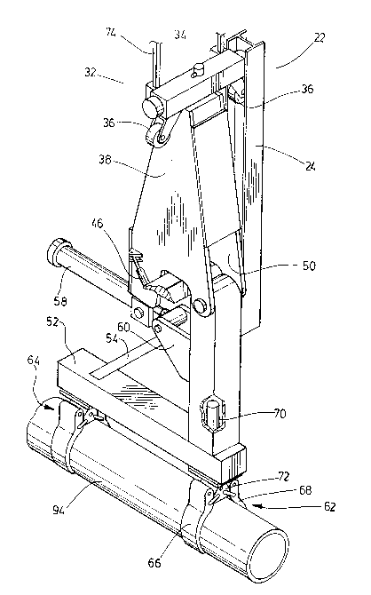
derrick 12 proximate to the rotary table 16. The machinery includes a guide 22
that is basically a pair of vertical I-beams 24, 26 in parallel relationship. These
are supported, suspended above the drill floor 14, by struts joining the I-beams24, 26 to the derrick 12. Two exemplary struts 28, 30 are specifically indicated25 in fig. 4. The guide 22 defines a vertical track -for displacement of a carriage
32. The carriage 32 has two principal parts: a rectangular frame 34 with wheels
36 that are fitted into the channels of the I-beams 24, 26; and a swivel 38. Theswivel 38 is mounted to the frame 34 with bearings 40, 42 to permit pivoting
' ~ ' ' ' :
,: ' ' '
-- , .
aboLIt a gellelally vcltical ~l~iS. A pair Or hydralllic cylinders 44,46 connected
between the carri~lge 32 I;ame 34 ancl the swivel 38, one to either sid~ oî the
swivel 38, can bc operatecl incli~ ally to pivot the swivel 38 in opposing
directions.
A pipe clamping mechanism 48 is connected to the carriage 32.
The clamping mechanism 48 includes a rigid fiame comprising arms 50,52 at
right-angles to one another and a reinforcing strut 54 extending between the
arms S0,52. A c]evis 56 ~orms a pivot joint between one arm 50 and the
swivel 38 that permits the clamping mechanisrn 48 to pivot about a horizontal
axis. A hydraulic cylinder S$ is connected with a clevis (not indicated) to the
base of the swivel 38 and through a triangular plate 60 to the arm 50. When
actuated, the hydraulic cylinder 58 pivots the entire clamping mechanism 48
through a range of about 90 degrees The clamping mechanism 48
consequently travels vertically with the carriage 32 and pivots about a generally
horizontal axis relative to the carriage 32. As mentioned above, the swivel 38
itself pivots, permitting the clamping mechcmism 48 to pivot about a vertical
axis relative to the carriage frame 34. The pair of hydraulic cylinders 44,46
connecting the swivel 38 to the carriage frame 34 can pivot the clamping
mechanism 48 through a range of about 30 degrees about the vertical axis.
The clamping mechanism 48 includes a pair of clamps 62, 64,
spaced-apart along the arm 52. One clamp 62 is typical. It comprises a pair of
jaws 66, 68 that are mounted with pivot pins to the arm 52 for displacement
toward and away from one another. A hydraulic cylinder 70 is attached to the
arm 50, and a conventional mechanical linkage couples the hydraulic cylinder
70 to the jaws 66, 68. The linkage includes a triangular member 72 with one
vertex pivoted to the piston rod (not numbered) of the hydraulic cylinder 70.
The other vertices are connected with link arms to each of the jaws 66, 68.
Contraction of the hydraulic cylinder 70 causes the jaws 66, 68 to be drawn
- 6 -
'
.
.
~, ' ' ' ' '
' ~ ,
together to gl ip a pipe (as shown in fig. 3 ancl 4). E~xp~msion ol the hydraulic
cylincler 7() pivots the jaw~ 66, 68 to a releasing orient~ltion (not illustrat~d)
clear of the pipe. The other clamp 64 i~ operated simultaneollsly in the same
manner, Ising a similar hydraulic cylinder (not ill~lstrated) and similar linkage
5 (not illustratecl) located in the arm 52.
A~l elevator 7~ displaces the carriage 32 along the guide 22
between a bottom-most position (illustrated in fig. 1) and various higher
positions. The elevator 74 is a continuous chain drive with upper and lower
chain sprockets rotatably mouneed to the guide 22. One end of the chain is
10 fixed to the frame 34 of the carriage 32. The upper sprocket is rotated by a
hydraulic motor to raise or lower the carriage 32. The elevator 74 may have a
loading-bearing capacity of about 8 tons. Alternatively, a winch and wire rope
can be used to raise and lower the carriage 32 in a conventional manner.
A conveyor 76 of the endless belt type is aligned with or directed
15 toward the guide 22. The conveyor 76 has a pair of chain wheels at either end(only chain wheels 78, 80 apparent in fig. 1) that carry two endless runs of
chain (only chain 82 apparent in fig. 1) in a generally horizontal orientation,
parallel and spaced apart. The chains carry steel slats that have polyurethane
coatings to reduce friction and noise. The slats are simply connected
20 transversely between the chains, slightly spaced-apart from one another alongthe length of the chains. A conventional motor (not illustrated) drives the chain
wheels to convey pipe between a storage area (not illustrated) and the drill floor
14, through a Vee door 88 of the derrick 12 facing toward the conveyor 76.
That Vee door 88 is substantially identical to the Vee door 90 more clearly
25 illustrated in the various views. The conveyor 76 has a free-wheeling mode ofoperation, when de-clutched from the motor. The conveyor 76 is used not only
to transfer pipe to and from the drill floor 14, but also to assist in raising and
- 7 -
;' : ' . ~ ' ~ `~
''
:
: - .
.
lowel ing hcLIvier d()wn~ ole pipcs, as cxplaine(l more fully below. Several
alignecl conv~ys may in ~ct be llsed to convey pipe to and ~rom more distant
pipe lines aboard the drill rig l~), being remove(l or aclcled as required.
Figs. I ancl 2 illustrate variolls stages in hanclling a heavy well
casing 92. In fig. 1, the well casing 92 has been conveyed horizontally ~rom
the storage area until one end portion 9~ has erltered the Vee door 88. The
clamping mechanism 48 has been pivoted downw~rdly and the carriage 32 has
been lowered to locate the clamps 62, 64 about the casing end portion 94. The
hydraulic cylinders associated with the clamping mechanisrn 48 are then
actuated to grip the casing end portion 94. The conveyor 76 is placed in its
free-wheeling mode.
The elevator 74 is then actuated to draw the carriage 32
upwardly along the guide 22. This raises the casing end portion 94 through
various position shown in phantom outline ;n fig. 2. The opposing lower end
portion 98 of the casing 92 travels along the free-wheeling conveyor 76 toward
the guide 22. The conveyor 76 ensures that the lower end portion 98 travels
laterally with little resistance in response to raising of the other casing end
portion 96. With further raising of the casing end portion 96, the well casing
92 assumes steeper inclinations, as the lower end portion 96 progresses toward
the Vee door 88. Eventually, the casing 92 is suspended above the drill floor ~ .
14 and its centre of gravity is positioned below the horizontal pivot joint formed
between the swivel 38 and the clamping mechanism 48. The hydraulic cylinder
58 connected between the swivel 38 and the -frame of the clamping mechanism
48 may then be actuated to orient the well casing 92 in a vertical orientation (as
shown in solid outline in fig. 2). The swivel 38 may then be rotated by
actuating an appropriate one of the pair of hydraulic cylinders 44, 46 to locatethe well casing 92 over the opening 18 of the rotary table 16. The well casing
92 may then be handled in a conventional m~mner.
, ~ - . -
-
.
,. : ~` ':
Figs. l ancl 2 shoul~l be examined and compared with prior art
proposals. It will be apparent that the maximum moment that the hydrawlic
cylinder 58 m~lst accommoclate arises when the well casing 92 is vertically
oriented. That moment is comparatively ~mall.
Heavy down-hole pipe can be removed from a pipe string by
essentially reversing the steps described immediately above. The conveyor 76
is partic-llarly ~lseful in such operations. During removal, the lower end of the
suspended pipe must eventually contact a horizontal surface. The inclination of
the pipe upon contact will be substantially the steep inclination of the well
casing 92 as suspended and allowed to swing under its own weight. Friction
between the lower end of the pipe and the surface may impede lateral
displacement. The i~ree-wheeling conveyor 76, however, encourages the
req~lired lateral movement. An immediate alternative is to operate the conveyor
76 under power to produce the required lateral movement. The speed of the
conveyor 76 may be synchronized with the vertical speed of the carriage 32
(both during raising and lower of the pipe). A programmable logic controller
may be used to coordinate operating speeds. A variety of powered conveyors
may be used for such purposes. Another alternative is to form an inclined
surface extending outwardly from the Vee door 88 and leading to a horizontal
conveyor (comparable to a surface presented by a conventional catwalk).
However, the physical geometry of the drill rig may determine the preferred
approach.
Lighter drill pipe may by carried by the conveyor 76 in a
horizontal orientation until one pipe end has entered through the Vee door 88
and located upon the drill floor 14. The clamping mechanism 48 may then be
engaged with the pipe end, and the hydraulic cylinder 58 operated to maintain tothe pipe in its hori~ontal orientation while the entirety of the pipe 100 is simply
raised toward the top of Vee door 88. It may then be rotated directly through 90
: . . .. .
,- ,
cleglee~li, placing thc clrill pipe in 1 VertiCII orierltation above the drill floor 14.
It will be apprecilted that particular embocliments of the
invention have been clescribed and that modificcltions may be made therein
without departing from the spirit of the invention or necessarily departing fromS the scope of the appended claims.
- 10-
. .. ..
: . : .:
'
'