Note : Les descriptions sont présentées dans la langue officielle dans laquelle elles ont été soumises.
2~63~9
APPARATUS AND METHOD FOR THE MANUFACTURE
OF HOT-ROLLED STEEL
BACKGROUND OF THE INVENTION
1. FIELD OF THE INVENTION
The invention relates to an apparatus for the
manufacture of hot~rolled material comprising a
continuous casting machine for casting a slab and
reduction means in line with the continuous casting
machine for reducing the thicknes~ of the slab into a
strip. The invention also relates to a mathod ~or the
manufacture o~ hot-rolled steel.
2. DESCRIPTION OF THE PRIOR ART
An apparatus and method of the type mentioned
above are known from the publication DE-OS 3840812.
This known apparatus comprises a continuous casting
~h;n~ for casting thin slabs and reduction means in
the form of a four-high stand with four rolls. The
continuous casting machine casts a slab with a
thickness in the range 50 mm to 100 mm which the
reduction means reduce to a thickness of approximately
25 mm. In order to achieve the desired reduc-tion in
thickness, it is usual to place several four-high
stands directly one af~er the other. The entry
temperature of the slab in the first four-high stand is
of the order of 1100~C.
2~63679
A number of disadvantages are assoclated with
thè use of sevexal four-high stands:
- complicated arrangements are required for
harmonizing the rolling spee,d be-tween each of
the several mill stands and with the casting
speed of the continuous castiny machine;
- there is high thermal loading of the work
rolls of each four-high stand;
- ~emperature losses of the workpiece on the
several mill stands are relatively high;
- there is high wear and tear on rolls as a
result of the n~ h~r of rolls (several work
rolls);
- the long stay time in the rol~ng unit causes
increased oxide layer formation;
- the end-to-end length of the rolling section
is large;
- capi-tal investment is high.
SUMMARY OF THE INVENTION
The object of the present invention is to
provide an apparatus for manufacturing hot-rolled steel
which at least partly avoids or re~uces these
disadvantages.
In accordance with the invention there is
provided apparatus for the manufacture of hot-rolled
steel strip, comprising a continuous casting ~ch;ne
20S3~79
~or casting a slab and reduction means comprising at
lèast one roll stand for reducing the thickness of said
slab to make strip, said reduction means being
incorporated in line w~th said continuous casting
5 -~h~ n~. to per~orm continuous rolling o~ said slab,
characterized in that said roll stand is a two-high
roll stand having a pair of rolls adapted for hot-
rolling of said slab into strip.
Preferably the apparatus has reheating means
after the two-high roll stand, and the two-high roll-
stand is the sole reduction means after ~ull
solidification of the slab and be~ore entry o~ the
strip to the reheating means.
Surprisingly it has been found that a single
15 two-high stand produces at least the same metallurgical
results as several four-high stands. In addition using
a two-high stand can achieve, among other things, the
following advantages:
- simple control over rolling speed whereby the
entry velocity of 8-0.1 m/min or slower lies
adequately within the range of variation of
the roll;
- low thermal loading of the work rolls due to
their large ~; ~n~
25 - temperature losses of the workpiece are less;
- less wear and tear on the rolls;
206~679
- the period of exposure of the thln slab to the
atmosphere is shorter so that less oxide
forms;
- with a single mill stand, it is simpler to
remove the oxidè on account o~ ~he easier
~ accessibil~ty compared with several four-high
stands;
- when removing oxide using high-pressure water
~ets, coolin~ takes place only once and not
several times as is the aase wi-th several
four-high stands.
Trials on steel grades St 37, ~t 52 and an IF
grade using the apparatus in accordance with the
invention showed that it is possible in one single pass
to achieve a reduction in thicknes~ of 60 mm to lass
i than 20 mm, wherein surprisingly the strip also
displayed a surface free of cracks.
It is preferable that the R-H-ratio, i.e. the
:~ ratio of the radius of each of the rolls of the two-
high roll stand to the thickness of the slab to be
reduced, is at least 3, and in particular that the R-H-
ratio is at least 6. In practice, with two-high roll
stands, at lower R-H-values than those mentioned here,
and for a reduction ~cee~;n~, for ~X.-mple, 50% or
preferably over 60~, the roll forces on the mill frame
become too high, or the work roll bends to such an
~636~
extent that improper defects of shape occur.
It should be noted tha~ a maximum is imposed
on the R-H-rat~o on account o~ mill technology
considerations. Accordingly for ingot rolllng a
maximum R-H-ratio of appro~imately 115 applies, for
hot-rolling approximately 135, and for cold-rolling
values varying from 400 to 2100. At greater R-H-ratios
the rolling process becomes unstable as a result of the
displacement of the neutral line. It is then not
certain that the steel to be rolled will feed through
the roll gap. Moreover, such a high degree of
daformation of the rolls then occurs that the rolled
product has unacceptable de~ects of shape.
Known rolling processas are carried out with
an apparatus wherein the R-H-ratio lies close to those
upper limits. It has been found that the advantages
mentioned above may also be achieved with much lower R-
H-values in the present invention.
A strip which is rolled with the aid of such
an apparatus is particularly suited to being
subsequently rolled out ferritically into a thin strip
with good deformation properties.
Stable feed of the slab to be rolled is
obtained when the square root of the ratio of ths
thickness reduction of the thin slab and the radius of
each roll of the two-high roll stand is less than 1.1
~"
~0~3~79
times the arc tangent of the coefficient o~ friction
between the slab and the roll, i.e. J(A t/R) < 1.1 tan 1f,
where At = amount of thickness reduction, R is roll
radius and f the coefficient of friction. This ratio
is also called the angle of bite (in units of radians).
When this condition is fulfilled, the angle of bite
between the roll and the slab becomes so small in
relation to the friction that stable feed of the slab
is ensured.
It is preferable for the ratio between the
radius of each of the rolls of the two-high roll stand
and the hetght of the roll gap to be at least 10. The
greater is the radius of the roll relative to the
height of the roll gap, the greater is the amount of
slip occurring in the roll gap during rolling. Within
certain limits, more slip has an advantageous effect on
the stability of the rolling process. However, one
effect does occur in the roll gap that is known by the
name "stick". This is used to indicate that there is a
zone in the roll gap in which the peripheral speed of
the roll and the velocity of the thin slab are
approximately equal. If the stick value is too high
this has a disadvantageous effect on the surface
quality and on the isotropy of the rolled thin slab.
Equally it has been found that, within certain limits,
the relative size of the zone where stick occurs
2063~79
increases less rapidly with the height of the roll gap
than the slip.
It is further preferable for the radius of
each of ~he rolls to be at leas-t 400 mm. It has been
found that, even with large reductions as mentioned
previously, within the loading limit,s of the mill
stand, the forces on it then ~ ;n unch~n~ed during
the rolling of a normal thin slab, and that no
unacceptable roll deformation occursO
, !
The appara-tus in accordance with the invention
may be provided with means for cast rolling for
reducing the slab in thickness before its ~ull
solidifiaation, i.e. where its core has not yet
solidified. Cast rolling influPncP~ the in-ternal
structure o~ the slab and the strip manufactured by it,
so that, following ferritic rolling, a structure
results which makes the material particularly suitable
for formable steel.
Preferably, between the continuous casting
; 20 ~Ch~ n~. and the two-high roll stand, a high-pressure
liquid iet is placed for 1- ving an oxide layer on the
slab, and in particular in that several liquid jets are
placed next to each other across the width. These jets
may be controlled independently of each other in order
~5 to influence the amount of oxide 1~ v~d locally. This
allows the oxide scale formed on the slab to be removed
'
''''
.~,
.
2~3~79
and prevents parts of the oxide scale from being rolled
in.
In order to keep the reduction forces low and
to achieve a good quality surface, the apparatus is
preferably provided with a lubricant feed system for
applying a lubricant between the slab and the rolls of
the two-high roll stand. This can also produce an
improved structure.
As far as capacity is concerned, a good
linkage batween continuous casting machine and two-high
stand is obtained when the rolling speed of the two-
high roll stand lies between 0.01 and 30 m/min and
preferabl~ between 0.1 and 20 m/min.
In par-ticular, good harmonization of the
throughput of the continuous casting machine with the
throughput of the two-high roll stand can achieve an
e~tra advantage, when processing means are placed after
the two-high roll stand for rolling the strip
ferritically. This apparatus is suited to continuous
processing in the manufacture of formable steel with
cold strip properties.
T~e invention also provides a method for the
manufacture of steel strip comprising the steps of
continuously casting steel into slab in a continuous
casting mar.h;ne. and effecting reduction of said slab
into strip by hot-rolling at least in the austenitic
2~367~
region, characteri~ed in that hot-rolling reduction of
the slab takes place in a single pass through a two-
high roll stand 4 having a pair o~ rolls adapted to
effect reduction of the slab into strip.
Preferably said two-hi~h roll stand is
arranged in line with said continuous casting ~h;ne
for continuous rolling of said slab, and said single
pass through said two-high roll stand is the sole
reduction of said slab after full solidification
thereof and before reheating of the strip in a
reheating means.
This method can produce a strip with
properties which are at least equivalent to the
properties obt~ne~ with the known method, whlle the
thermal loss during rolling is less than wlth the
me-thod known from DE-OS-3840812.
A particular advantage is achieved when the
slab is reduced by at least 50~ in thickness in the
two-high roll stand and more especially in that the
thin slab is reduced by at least 60% in thickness. The
reduction percentage is the thickness reduction
relative to the input thickness of the thin slab. With
a conventional continuous casting ~h~ ne, at these
reductions a strip is ob~nP~ with a thickness of
approximately 20 mm.
With an exit thickness of the strip from the
~06367~
', 10
two-high roll stand of approximately 20 mm, this strip
is simple and quick to homogenize and is especially
suited to being rolled ferritically into formable
steel. t
Preferably -the thin slab is rolled under
operational conditions in which the slip coefficien~
increases as the degree of reduction increases. Here
! the slip coefficient is taken to be the relative
di~ference in velocity between the exiting strip and
the periphery of the roll compared with the peripheral
velocity of the roll. Depending on rolling parameters
including the coefficient of ~riction, there is a range
in which the slip coe~ficient increases as the degrea
of reduction increases. For the sake of the stability
of the rolling process it is an advantage to work
within tha-t range.
For the sake of the stability of the rolling
process it is furthermore an advantage if the thin slab
is rolled under operational conditions in which the
rolling force increases as the degree of reduction
increases.
Research has shown that, dependent on the
coefficient of friction, the slip coefficient and the
rolling force increase, L~ ~ n constant or decrease as
the degree of reduction increases. For the sake of
controllability 0~ the rolling process it is desirable
:"'
2~3679
11
to select the rolling parameters so that the rolling
takes place under the operational conditions defined
above.
Depending on the metallurgical composition of
the thin slab, the oxide on its surface influences the
lubricating action. This is particularly the cas~ with
low car~on steel grades cont~i n~ ng titanium.
For the sake of contxollability of the rolling
forces occurring, it is further desirable for the slab
thickness to be smaller than 100 mm.
The lnternal structure of the strip and the
surface of the strip are further il~ploved i~ the two-
hi~h stand lubricates during rolling.
The structure of the strip produced is
particularly suited to subsequent ferritic rolling,
especially when the slab is cast rolled with its core
still molten.
BRIEF INTRODUCTION OF THE DRAWINGS
The invention will be illustrated in the
following with reference to the accompanying drawings
of a non-limitative example. In the drawings :-
Fig. 1 is a schematic representation of anapparatus embodying the invention,
Fig. 2 is a graphical representation of the
temperature gradient of a point of the thin slab as a
function of the time in the case o~ a typical prior art
20S3~79
1~
process, and in the case of a method ln accor~ance with
the invention,
Fig. 3 is a graphical representation of the
relationship ~etween angle of bite and roll diame~er,
Fig. 4 is a graphical representation o~ the
rolling force as a function of the roll diameter,
Fig. 5 shows the trend of the rolling force as
a function of the exit thickness of the rolled thin
slab,
Fig. 6 shows the trend of the slip coefficient
and the stick percentage as a ~unction of the exit:
thickness of the rolled thin slab,
Fig. 7 shows the relationship between the slip
coe~ficient and the exit thiakness for different values
of coe~ficient of friction,
Fig. 8 shows the relationship between the
specific rolling force and the exit thickness for
different values of coefficient of friction.
DESCRIPTION OF THE ~ ~K~ED EMBODIMENTS
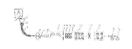
Fig. 1 shows the tundish 1 of a continuous
casting machine for casting thin slabs. The liquid
steel from the tundish flows into the mould 2. The
slab leaving the mould has a thickness of for example
60 mm at an exit velocity of 5 m/min. In the roller
track 3 there is an apparatus (not shown in the
drawing) for cast rolling of the not fully solidified
2~367~
13
slab (this is known as squee~ing while solidifying).
The slab thus leaves the roller -track 3 with a
thickness of 45 mm and at a velocity of 6.6 m/min and a
temperature of approximately 1100~C. This slab enters
the two-high roll stand 4 for which, for example,
blooming rolls from a blo, ~ n~ mill may be used. The
strip exiting from the two-high roll stand 4 has a
thickness of approximately 15 mm at an exit velocity of
approximately 20 m/min and a temperatuxe of
approximately 1050~C. Placed before the two-high roll
stand 4 there may be a high pressure jet system tnot
shown) for removing oxide scale from the slab and a
feed system for a lubricant (also not shown)~
~f desired, s~ears 5 may be used to cut o~f
the head and tail of the strip rolled by the roll stand
4. If necessary the strip may be heated up to
approximately 1120~C in an induction furnace 6 direct
coupled to the stand 4 for continuous processing of the
strip. If an induction furnace is indeed necessary,
then it may be smaller than in the current state of the
art because the temperature drop of the thin slab is
less in the apparatus of this embodiment. A so-called
coil-box 7 may be placed after the induction furnace in
I order to Cf ~ e~ate for any, possibly temporary,
throughput discrep~nf,~ Q~ with the subsequent processing
plant. After the coil-box 7 is the start of apparatus
: ' .
.
~6~7g
14
for further rolling of the strip. The single pass
through the two-high roll stand ~ may be the sole
reduction of the fully solidified steel in the
austenitic region, or there may be subsequent
austenitic reduction before ferritic rolling begins.
Ferritic rolling comprises a reduction of the strip in
the ferritic temperature range and above 200~C. A
scale breaker 8 in the form of a high pressure jet
Le-.loves o~ide. Three four-high stands 9, 10 and ll
reduce the strip from 15 mm at 0.33 m/s and 1020~C to
1.5 mm at 3.3 m/s and 880~C. ~he strip is cooled down
in cooling installation 12 to the desired temperature
range for ~erritic rolling in mill stand 13. The exit
velocity of mill stand 13 is 7.0 m/s with a strip
thickness of 0.7 mm. Followin~ any cooling in a
further cooling unit 14 the rolled thin strip is
coiled onto one of the reels 15 or 16.
Unless otherwise stated, Figures 2-8 rela-te
throughout to a rolling process in which a thin steel
slab is rolled in accordance with the invention in the
austenitic temperature range from an entry thickness of
60 mm and a width of 1000 mm to a strip with a fin;~he~
thickness of 15 mm using a two-high roll stand of which
each roll has a radius of 670 mm and in which the e~it
velocity of the strip is 0.5 m/s.
Fig. 2a shows the temperature gradient of a
~0~3~7~
point o~ the thin slab as a function of the time in a
rolling process in accordance with a typical process in
the current state of the art, wherein the thin slab is
reduced into strip in three reduction stages. The
reduction stages are successively 60-~5-25 15 mm, and
the radius of each work roll of each four-high stand is
350 mm. The spacing between each of the four-high
stands is 5 metres. The horizontal axis in the figure
indicates the time in seconds; along the vertical axis
is the temperature of a point of the thin slab. 'rhe
figure shows that in to-tal there is a temperature drop
o~ approximately 190~C.
Fi~. 2b shows the temperature o~ a point of
the thin slab when rolled with a single two-high roll
stand in accordance with this invention. This ~igurs
shows that the temperature drop is now only
approximately 90~C. Moreover, comparing the two
diagrams in Figures Za and 2b shows that with the
apparatus in accordance with current state of the ~rt
the rolling process lasts approximately 92 s and with
the apparatus in accordance with the invention just 45
s. Consequent-y this also substantially decreases the
time in which oxide formation can occur.
- Fig. 3 shows the relationship between angle of
Z5 bite (vertical axis) and roll diameter (horizontal
axis). Here the angle o~ bite is given in degrees.
.
2~367~
The angle of bite (in radians) is defined as the -the
square root of the ratio between the thickness
reduction during rolling and the radius of the roll~
The horizontal line a in the figure also indicates the
arc tangent of the coefficient of friction, set here at
0.27.
Figure 3 shows that for a radius of the roll
greater than 620 mm the angle of bite is smaller than
the arc tangent of the coefficient of friction so that
stable input of the thin slab into the two-high roll
stand is achieved.
Fig. 4 plots the rolling force during rol;ling
expressed ln MN agalnst the radius of the roll at a
coe~ficient of friction of 0.~7. This figure shows
that the rolling force during rolling of a roll with a
radius of over 620 mm will exceed 37 MN.
Fig. 5 shows the trend of the rolling force
expressed in MN as a function of the exit thickness of
the thin slab rolled into strip with an entry thickness
of 60 mm. The figure shows that under these conditions
the rolling forces remain within the limits of two-high
stands available in practice up to an exit thickness of
approximately 6 mm. For smaller exit thicknesses the
rolling force increases rapidly~
Fig. 6 shows the relationship between the
stick percentage and the exit thickness of the thin
20~3~9
17
slab rolled into strip curve a. Here "stick" is taken
to be the occurrence of a zone on the surface of the
thin slab in the roll gap that has the same velocity as
the periphery of the roll. The stick percentage is the
component of the arc of contact at the roll gap in
which stick occurs expressed in percent.
Stick has a negative effect on the rolled
material properties. In the case of small reductions,
for example with an exit thickness of over 35 mm at a
coefficient of friction of 0.27, no stick occurs. When
stick does occur, plastic deformation takes pLace
through shear. This shear can have a negative effqct
on the quality of the surface. Furthermore, this kind
of de~ormation means that, taken over the thickness,
the plastic deformation is not everywhere the same.
This proceeds from pure shear to pure normal
deformation of the material, depen~;ng on the magnitude
of the stresses. The r-value of the steel is
negatively affected by high stresses. Curve a moves
upwards as the coefficient of friction increases.
Fig. 6 also gives the relationship between the
slip coefficient ~curve b) and the exit thickness.
Here the slip coefficient is defined as the ratio of
the difference between the velocity of the exiting
strip and the periphery of the roll expressed as a
percentage of the roll peripheral velocity. According
~3679
to Fig. 6 the slip coef~icient, illustrated hers for a
coèfficient of friction of 0.27, increases as the exit
thickness reduces, and thus also with increaslny degree
of reduction of the slab. Curve b ends at the top at a
maximum value detel ine~ by the ~ m admissible
deformation of the roll. For incr~sing coefficients
of friction curve b moves towards the top right.
Surprisingly it has been found that when using
a two-high roll stand for reducing a thin steel slab,
conditions exist wherein the slip coefficient increases
with increasing reduction. In a rolling process this
is only the case under precisely selected conditions.
Figures 7 and 8 serve by way of explanation.
Fig. 7 shows the relationship between slip
coefficient and exit thickness, ~or various values of
coefficient of friction and a radius of the roll of 620
mm.
The series of curves shows that, under the
given conditions, for a coefficient of friction of 0.18
the slip coefficient is independent of the reduction.
For higher coefficient of friction values the slip
coefficient increases with incre~sin~ reduction. In
the latter case the slip coefficient can be a limiting
factor on the magnitude of the reduction. For a stabl~
rolling process, this factor should not become zero and
must preferably be con~iderably hl~her. The situation
20~3~79
19
of low friction can occur where in the case of ferritic
rolling the friction has to be kept low by lubrication.
Fig. 8 shows the trend of the speci~ic rolling
force as a ~unction of the exit thickness in the case
of three different values of coef~icient of friction.
Here too, at a coefficient of friction of 0.18 a
change of behaviour has been found to occur. At a
higher coefficient of fric~ion than 0.18, the roll~ng
force increases as degree of reduction increases. In
the opposite situation, large reductions may cause
instability in the rolling process.