Note : Les descriptions sont présentées dans la langue officielle dans laquelle elles ont été soumises.
CA 02069480 1998-08-13
-1-
TITLE
DENTAL COMPOSITION CAPSULE
DESCRIPTION
The present invention relates to a dental composition capsule such as a dental
amalgam
capsule.
FIELD OF THE INVENTION
Dental amalgam capsules have been known for some time and typically comprise
two
compartments. One compartment contains dental alloy and the other contains
mercury.
The components in the compartments are brought together such as by depression
of a
plunger to rupture a partition. The resulting alloy and mercury mixture is
then
amalgamated such as by the placement of the capsule into a high speed
amalgamator.
A disadvantage of previously known capsules is that once the amalgam has been
formed,
the capsule has to be opened, and the amalgam has to be manually removed and
then
placed into a cavity of a tooth to be restored.
This operation requires a dental nurse to empty the amalgam from the capsule
into an
amalgam well. Then a amalgam carrier is loaded from the amalgam well. The
loaded
amalgam carrier is handed to the dentist who then injects the amalgam into the
tooth
cavity. The dentist usually returns the amalgam carrier to the nurse for
reloading. This
operation may be repeated from 3 to 5 times depending on the size of the
amalgam mix.
The above described mode of operation is time consuming and also exposes the
dental
nurse to upset amalgam with attendant danger of the nurse being exposed to
mercury
vapour.
CA 02069480 2002-07-02
-2-
In addition, amalgam is often dropped out of the amalgam carrier as the
carrier is being
handed to the dentist. Also, amalgam carriers are often rendered inoperable
after a short
working life in that amalgam can work its way into the carrier and cause it to
jam. Also, the
carrier can retain set amalgam from previous operations with the risk that set
amalgam can be
mixed with fresh amalgam such that a mixture of set and upset amalgam can be
placed in a
cavity.
SUMMARY OF THE INVENTION
The present invention provides a dental composition capsule, such as a dental
amalgam
capsule, in which the composition, such as amalgam, can be placed directly
into a tooth
cavity without the need for prior removal as with previously known devices.
In accordance with one aspect of the present invention, there is provided a
dental composition
capsule comprising a body and a conduit extending from the body, a chamber
within the body
and the conduit, said chamber being arranged to contain metal which is liquid
at ambient
temperature and particulate dental alloy in separated condition, the conduit
having an outlet
end, means being provided for enabling the liquid metal and the particulate
dental alloy to
contact one another in a mixing zone within the chamber, and to be formed into
a
composition, the conduit being of lesser external dimension than the body,
there being
associated with the capsule a longitudinally rigid but transversely flexible
pusher member
which is arranged to be pushed through the mixing zone to dispense composition
from the
conduit at the outlet end thereof, wherein the mixing zone is flee of
constrictions throughout
its entire length extending to the outlet end of the conduit.
CA 02069480 1998-OS-O1
-3-
BRIEF DESCRIPTION OF THE DRlIWINGS
The present invention, will now be described, by way of
example, with reference to the accompanying drawings, in
which:-
Figure 1 is a side elevation of a dental amalgam capsule in
accordance with the present invention in unactivated state
and with an amalgam delivery conduit in straight condition;
Figure 2 is a view similar to Figure 1 with the amalgam
capsule in activated state;
Figure 3 is a plan view of the capsule of Figures 1 and 2;
Figure 4 is an underneath view of the capsule of Figures 1
and 2;
Figure 5 is a vertical section through the capsule as shown
in Figure 1 along the lines X-X of Figures 3 and 4;
Figure 6 is a vertical section through the capsule as shown
in Figure 2 along the lines X-X of Figures 3 and 4;
Figure 7 is a side elevation of an applicator for dispensing
amalgam from the capsule of Figures 1 to 6, with a capsule
of Figures 1 to 6 in place;
Figure 8 is a longitudinal sectional view of the applicator
and capsule of Figure 7 prior to commencement of dispensing;
and
Figure 9 is a view similar to Figure 8 showing the
applicator and capsule in a condition ready to commence
dispensing.
Figure 10 is a view similar to Figure 9 showing the
condition of the applicator aad capsule inQnediately after
WO 91/07924 , ~ (. ~..~ 6 9 4 8 0 p~'/pU90/00566
- 4 -
dispensing has ceased and the capsule is ready to be
disposed of ;
Figure 11 is a perspective view of a leading end of the
applicator of Figures 7 to 10 without a capsule in place;
Figure 12 is a perspective view of a bending tool for use
with the capsule of Figures 1 to 6;
Figure 13 is a longitudinal section through the bending tool
of Figure 12;
Figure 14 is a side elevation of a leading portion of the
applicator of Figures 7 to 10, with a capsule of Figures 1
to 6 in place showing the bend tool of Figures 12 and 13 in
operation;
Figure 15 is a plan view of a pawl of the applicator of
Figures 7 to 10; and
Figure 16 is a view similar to Figure 5 showing an
alternative embodiment of a capsule in_accordance with the
.w -present invention.
.DESCRIPTION OF THE INVENTION
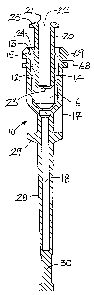
In Figures l to 6 of the accompanying drawings there is
20~,shown a dental amalgam capsule 10 comprising a body,..l2. .The
body l2 contains a generally-cylindrical shaped recess
.., -extending from the upper end:l3 as seenin Figure 3: The
__..,-~,generally~:cylindrical shaped recess,however tapers inwardly
away from the said upper end 13.
Further, the generally cylindrical shaped recess contains a
mercury:container l4y:of complementary outer--shape.to the
internal shape of the said recess. The generally:«=.~:
cylindrical shaped~recess contains a circumferential groove
15 into which a portion of the mercury container 14 fits
- ~0~9480
_, ~.: ;... ~~ ; z ~~'1 PCT/AU90/00566
.' WO 91/07924 . ~ :.
. .. '. a ... :~
- 5 -
such as by deformation so as to prevent the mercury
container 14 moving longitudinally inadvertently.
The capsule 10 contains a chamber formed of first and second
compartments to be described, in the unactivated condition
of the capsule 10 best seen in Figure 3.
The mercury container 14 contains a cylindrical first
compartment 16 which contains mercury. Inwardly of the
inner end of the compartment 16 the chamber is closed off by
a thin membrane or partition 17. The partition 17 divides
the chamber into the first compartment 16 and a second
compartment 18. An outer end of the compartment 16 remote
from the partition 17 is closed off by a slidably mounted
plunger.20.. The plunger 20 is in the~form of an elongated
shaft which fits snugly into the compartment 16. The
plunger 20 has an open outer end 21. A longitudinally
extending recess 22 extends inwardly from the open end 21.
The recess 22 has an inner end whichwis closed off by a thin
membrane 23.
In the unactivated.conditiowof ahe capsule 10 shown in
20. Figures 2 and 4, the initial location of the plunger 20 is
_.. ; determined by a locating ring 24.(see Figure.3) which
extends around the periphery of the"plunger-v20:
.. .: 'As '.:can be . seen in Figure . 3 , '-the plunger 20 'ia =initially
disposed so that thevlocating ring 24 is disposed adjacent
:25 wthe end l3vremote from the partition 17:--Further,~the
. ' wplunger v20 .has a .head 25 at the endthereof remote 'from the
--.. w- body l2 iw the unactivated condition:' '
The second compartment 18 is partially located within the
body l2 and partially in an elongated conduit 28 which
WO 91/07924 '~ ~ 6 ~ 8 ~' :, PCT/AU90/00566
6
extends away from the body 12 and is of lesser external
dimension than the body 12. A transverse connecting portion
29 extends between the body 12 and the conduit 28.
The second compartment 18 has an inner end sealed by the
partition 17 in the unactivated condition of the capsule 10
and an outer end sealed by an integrally formed plug 30.
The second compartment 18 contains a quantity of dental
alloy in particulate form. As can be seen in Figures 3 and
4, the internal diameter of the. compartment 18 is less than
that of the compartment 16.
In operation, an operator pushes the plunger 20 into the
body 12 until the head 25 is in contact with the body 12 as
shown in Figures 2 and 4. This action firstly pushes the
mercury in the compartment 16 against the partition 17 and
hydraulic pressure applied by the mercury ruptures the
partition 17. Continued depression of the plunger 20 expels
the mercury from the compartment 16. The partition 17 may
be an integral part of the capsule 10 or it may be a
separate member formed of a plastics or metallic foil
affixed in place by any suitable means. The partition 17 is
broken.under.hydraulic pressure from the mercury as applied
to the .mercury""by.;the .plunger .;20. The plunger..20 has an
.,;interference fit withathe sides~of the.containerrl4 so that
no mercury can escape..past the.:plunger 20. As the plunger
25-,20 is depressed,.the_locating ring 22.is pushed along the
sides; of the-mercury container l4 and in this connection,
the mercury container,l4 is preferably formed of relatively
soft material so as to accommodate the ring 22 by
deformation. The depression of the plunger 20 and the
f,;~;'W091/07924 - ~j~'~.~r~~t;~r° PCT/AU90/00566
~i;;.,.ly,~.t;:.
7 -
breaking of the partition 17 and the continued depression of
the plunger 20 causes the mercury to be expelled from the
compartment 16 into the compartment 18 to contact the alloy
powder in the compartment 18.
Preferably, the partition 17 is such that it breaks in a
petal like formation and the petals are conveniently folded
into a slight recess (not shown) in the walls of the
interior of the body 10. The breaking of the partition 17
into a petal like formation may be facilitated by forming
lines of weakness in the partition 17. These lines of
weakness may simply be portions which are relatively thin
compared to the rest of the partition 17 and may have a
thickness of, for example, O.l to 0.2 mm. Preferably, the
lines of weakness are formed in a cross.
The retention of the broken portion of the partition 17 on
the interior walls is preferable to having a partition 17
which is broken away from the wall of the chamber upon
activation because the non-broken away partition 17 does not
become mixed with the amalgam. Further, as can be,seen in
_ Figures 3 and 4 the partition 17 preferably has. a central
portion,generally at 90°_ to the axis of the capsule which
central, portion containsthe line of weakness, and a first
~- peripheral ring which surrounds the central portion.-and is
di.sposed_at an acute angle to a plane running_through the
25._. ,central--portion of -the partition 17. Further,~..the -membrane
23_is preferably,of similar, shape. having-a:central portion
generally at 90° to the axis of the capsule:flanked by a
second peripheral ring which is disposed at an acute angle
to a plane running through the central portion of the
:w
;: ; ~.: ._.;. . z. ,~, .
WO 91/07924 2-O'6~~ ~''~ ~"' PCT/AU90/00566 ~~'
_ 8 _
membrane 23. However, it is preferred that the outer angle
of the second peripheral ring be slightly less than the
acute angle of the first peripheral ring as it is found that
this leads to more efficient expulsion of the mercury from
the compartment 16.
After this operation has been accomplished the capsule 10
can be placed in a high speed amalgamator and triturated for
as long as is necessary to produce a homogeneous amalgam in
the compartment 18 after the plunger 20 has been depressed.
It is found that certain types of amalgam such as dispersed
alloy containing amalgams will not mix readily in the
restricted.space provided by the elongated compartment 18.
However, certain amalgams having a highly reactive surface
area and not requiring a high energy input for amalgamation
such as "Lojic Plus", "Lojic" and "Permite" produced by the
present applicant will mix in the compartment 18.
After the mixing process the capsule l0 may be placed in an
applicator such as that shown in Figures 7 to 10.
Conveniently, the conduit 28 is flexible so that~it can be
supplied straight as shown in Figures 1 to 6 but can be
readily bent. by the dentist to any convenient
"-~ -' configuration:" This is conveniently done by a bending
- tool: ~ Further;- the plug -30 'has to be 'broken off before
"dispensing of'amalgam can take place:' In this connection
:-25 ==ahe ~ plug 30 -preferably has a frangible portion ~ ( not "shown)
.- -~to -facilitate"it wbeirig broken off at the "outer end 'of the
compartment 18. -. _ _
However, it is to be understood that the conduit 28 could be
rigid and supplied in any already bent configuration to the
f ''~,_;~ WO 91/07924 - ~ ~ ~ :~y ~; ~::, PCT/AU90/00566
g
dentist.
In Figures 7 to 10 of the accompanying drawings there is
shown an applicator 40 comprising an elongated hollow,
generally cylindrical body member 42. The body member 42
comprises an intermediate portion 43 with flat sides. A
lever 44 is pivotally connected to the body member 42 at the
intermediate portion 43.
The lever 44 has an inner end which pivots about a pin 46,
in use. The inner end of the lever 44 is formed with a pair
of depending spaced apart plates 47 (see Figure 7) which are
disposed externally of respective flat sides of the
intermediate portion 43. The pin 46 extends through opposed
apertures in the plates 47 and through the intermediate
portion 43.
There is an additional pin 48 which extends between a
further pair of opposed apertures in the plates 47 above the
body member 42 as seen in Figures 7 to l0. A coil spring 50
(see~Figures 8 to 10) is mounted about the pin 48 between
the'plates 47. The coil spring 50 has a first free end
which bears against the lever 44 and a second free end which
ibearsagainst ~a~ pawl member ~52. The pawlmember. 52 ,has a
forked inner~end.with apertured legs~52a mounted.~about the
pin 48 and with the'coil'~spring 50 located between the legs
-as shown in~Figure 15. The free ends of the coil~spring 50
25~vare biased outwardly~and normally. urge the lever 4~4 and~the
pawl 52 "apart ~ , ~ The pawl member has ~an outer end provided
with a tooth 53.
The applicator 40 also comprises an inching mechanism
comprising an elongated rod 54. The rod 54 enters the body
WO 91/07924 U PCT/AU90/00566 ':
- 10 -
member 42 through an aperture 56 in a trailing end 58
thereof. The body member 42 also has a leading end 59
configured to receive the capsule 10 as will be described.
The rod 54 comprises an intermediate ratchet portion 60
formed with a plurality of teeth 62 in succession. Each of
the teeth 62 has a steep face facing the trailing end 58 and
an opposed less steep face facing the leading end 59. The
teeth 62 are engaged in turn by the tooth 53 of the pawl 52.
The rod 54 has a forward end adjacent the leading end 59 of
the body member 42 which forward end contains a co-axial
recess 64 arranged to receive releasably a pusher rod 66.
The pusher rod 66 is formed of a material such that it is
longitudinally rigid whilst being transversely flexible.
This enables the pusher rod 66 to push amalgam through the
conduit 28 even when the conduit is curved as will be
described. The pusher rod 66 may be engaged with the rod 54
by being a snug fit. in the recess 64 but it can be engaged
by any other convenient means such as by being threadedly
engaged with the recess 64. However, it is preferred that
the pusher rod 66 simply have a snug,.push fit in the recess
64.which enables the pusher rod 66 to be released from the
,recess 64 once a capsule 10 has been used so that the pusher
rod 66 remains. inside the capsule....
The rod 54 also has a trailing end adjacent the end 58 of
the body member 42. The trailing~end of the rod 54 is
,~: ... '". .f ':: y :. .. ' :.. .. ". . . ~, - . .. . :' ~.. .. ..' ..': :..
..
provided with a knob 68 arid one or more position marking
circumferential grooves 70.
The body member 42 further comprises a stop member in the
form of a stepped plate 72 which is pivotally mounted about
,.~.. ~~.~.~e ~~.0
'w'~:"~ WO 91/07924 . ~ PCT/AU90/00566
- 11 -
a pin 74 which extends through the body member 42 to the
rear of the pin 46. The stepped plate 72 has a leading
portion 72a and a trailing portion 72b. The leading portion
72a has a leading end located between the inner end of the
lever 44 and the body member 42 and the trailing portion 72b
has a trailing end located within a recess in the body
member 42. The trailing portion 72b of the stepped plate 72
has a depending tooth 74 at the trailing end thereof which
tooth ?4 engages with the teeth 62 of the ratchet portion
60. The tooth 74 is shaped so that one side is inclined to
conform to a leading edge of one tooth 62 and the other side
is orientated so as to conform to the trailing.edge of the
next leading tooth 62. Further, a coil spring 76 is mounted
between the body member 42 and the leading portion 72a of
the stepped plate 72 and is mounted in respective opposed
apertures in these members. The coil spring 76 normally
urges the body member 42 and the leading portionw72a of the
stepped plate 72 apart such that the stepped plate 72 is
."pivoted about the pin 74 and the tooth 74 is firmly in
20.-~engagement with the,ratchet 60.
_~,~The capsule 10 described.above has a widened portion
adj acent. the end 13 which . widened portion _has : a ;.~ -;~
,._ , circumferential groove 68 and associated circumferential rib
69 at the end thereof adjacent the-plunger 20. In use, the
rib 69 is~engaged with a part circular:recess,76 at ahe~
.. ;leading end 59.of the:body member 42 whilst~the groove 68
engages with an outer, part circular-rib 78.~.wThe recess 76
and the rib 78 can best be seen in Figures 11 whilst the
engagement of the groove 68 and the rib 69 with the recess
~; ,i ,,
,' 2~ 0 ~ ~' ~~ 8~ ~
WO 91/07924 PCT/AU90/00566 fir'
- 12 -
76 and the rib 78 can best be seen in Figures 8 to 10.
Once the capsule 10 has been loaded the system is in the
configuration shown in Figures 7 and 8. The operator then
presses the lever 44 towards the cylindrical member 42.
This pivots the lever 44 about the pin 46 and so causes the
pawl 52 to push forwardly by means of the bolt 53 against
the leading tooth 62 of the ratchet member 62 and push the
inching mechanism forward by an increment. Simultaneously,
the leading portion 72a of the plate ?2 is depressed so that
the tooth 74 rides up the leading face of the trailing tooth
62 with which it is in contact. This action of the pawl 52
and the plate 72 pushes the rod 54 and hence the pusher rod
66 forward by an increment into the recess 21 of the plunger
20. This action is repeated until the pusher rod 66
contacts the membrane 23 of the hollow plunger 20.
This is indicated to the operator by.alignment of a groove
70 with the trailing end 58 of the body member 42. Upon
further depressions of the lever 44 and corresponding
incremental movement of the rod 54 the pusher rod 66 breaks
through the membrane 23 of the plunger 20 and then passes
the. ruptured partition 17 at the inner end of the first
compartment 16 to enter--the second compartment l8. This
.--..-.. . -,y-:incremental movement of the rod 54 and the- pusher rod 66 is
continued until the operator senses back pressure which
25~.rindicates .that..the amalgam in the second compartment 18-has
.'been pushed =.to the far end of the second compartment 18 of
the capsule' 10 adjacent the frangibly mounted plug 30.
For filling of most cavities the conduit 28 has to be bent
by the dentist prior to the breaking off of the plug 30.
-. ~'_ ~ 2~U'~'-~~~4 8 0
Ev WO 91/07924 . .. P~/AU90/00566
- 13 -
The particular degree of bend employed will vary from case
to case.
The bending.may conveniently be effected by a tool 80 shown
in Figures 12 and 13. As can be seen the tool 80 is
elongated tool has a first closed end 82 and a second open
end 84. A co-axial recess 86 extends from the end 84
partially along the length of the tool 80 as seen in Figure
13 for a length greater than that of the conduit 28.
Further, the open end 84 has an outwardly flared outer
portion 88.
The tool 80 is used by placing the end 84 over a conduit 28
of a capsule 10 in an applicator 40 as shown in Figure 14.
The tool 80 is pushed onto the conduit 28 until the end 84
engages with the transverse connecting portion 29 and the
conduit 28 enters the recess 86. With the end 84 in
.engagement,with the portion 29 the dentist then rotates the
tool 80 about the point of engagement with the portion 29 in
the direction of an arrow 90 so as to bend the conduit to a
desired angle which may be as much as 90°, or more from the
original. alignment of the conduit 28. The flared end 86 is
... .preferred.because it is, found that this reduces any tendency
y of ahe,end 84 to cut into the conduit 28 during_the bending
-r..',~ _.~Peration. ~. . : ; ::" : . ~ ._.. :, . .. ..., ..
-., .Once the bending operation.is complete the frangibly mounted
25. plug 30 is rbroken off. _
.":'The dentist . can now apply ythe ;amalgam directly , into .a cavity
_,-of,-a .tooth being restored by further incremental movement of
the rod 54 and the pusher rod 6,6 using the lever 44. The
amalgam is typically pushed out in incremental amounts until
,.
~~:2a69v~8~
WO 91J07924 PCT/AU90/00566
- 14 -
the dentist has filled the cavity.
Thus, the applicator 40 is designed so that the ratchet
member 62 is moved an incremental distance upon each
movement of the lever 44. At each incremental movement the
tooth 74 rides over the next trailing tooth 62 and engages
behind it.
Upon release of the lever 44, the coil spring 50 urges the
lever 44 away from the cylindrical member 42. The
engagement of the tooth 76 with the teeth 62 prevents the
rod 54 from moving inadvertently rearward.
The dentist can insert one or more quantities of amalgam
into the cavity of the tooth before commencing condensation
or he may commence condensation and then insert a further
quantity of amalgam into the cavity as required.
The application procedure can be repeated until the leading
end of the pusher rod 66 is adjacent the free end of the
conduit 28 from which the plug 30 was broken off. At this
- point substantially all of the amalgam has been used. The
capsule 10 aan then be discarded. Preferably, the capsule
10 is simply detached from engagement with the rib 78 and
~- -the-pusher-rod 66 remains inside the capsule 10: This may
-- be~-achieved by lifting the lever 44- so as to depress the
leading portion 72a of the. plate 72 and raise the trailing
- portion 72b so that the tooth 74 is no longer in engagement
with any of the teeth 62. Then the rod 54 can be removed
-~ - " 'from 'the -rearward 'end 58 ~ of the body member 42 . As the
w -- -"'conduit -28 '-is by now "typically 'bent there is a sufficient
degree of engagement of the pusher rod 66 with the interior
- of -the capsule 10 to enable the pusher rod 66 to remain in
_ ~.o_~~~~~v~
~'':~'W091/07924 ~~'' °' ' '~ '' ~ PCT/AU90/00566
- 15 -
the capsule 10 as the rod 54 is removed.
Further, the plug 30 is preferably configured so that it can
be inserted in the~recess 22 once the capsule 10 has been
used. In this wa~~ the used capsule 10 is sealed and escape
of residual mercury is reduced.
The second compartment 18 is designed so that it contains no
constrictions and is of substantially the same size and
shape throughout so that no effort is required to push the
amalgam therethrough. However, it is preferred that the
second compartment 18 have a slight outward taper from the
partition 17 to the outer end from which the plug 30 is
broken off as it is found that the slight outward taper
reduces the possibility of the amalgam packing in the
conduit 28. It is essential to avoid even slight reductions
in cross section of the conduit 28 to avoid packing of the .
amalgam in the conduit 28:
~~Preferably, the second compartment 18 which constitutes the
mixing chamber in the embodiment described, has an internal
diameter"from 1 to 3.5mm, more preferably from 2 to 3
millimetres. A conduit 28 of larger diameter would be
~difficult~'to insert~~~.into a toothcavity: Forsome
" '~ ~applications'such~'as filling small cavities; which are
' found~~frequentlylin children's teeth; the second compartment
'18 -may have an 'internal..diameter of about 1 to ~1. 5
millimetres y . . , . _ ... '. ,. .'.. .: .. : .. '. _ - _ .
' Further; the conduit'28.preferably~has a length in~~the range
'-'~ from l5~to SOmm, more preferably from-15 to 40mm, yet more
preferably from 20 to 30mm.
The mixing chamber is preferably from 20 to 30mm in length,
x:0:6:.9 4:$0::,
WO 91/07924 PCT/AU90/00566
- 16 -
more preferably from 30 to 40mm in length.
The capsule of the present invention can be manufactured
from plastics material by being moulded. The body 12 is
preferably relatively rigid, the plunger 20 is preferably
relatively rigid whilst the mercury container 14 is
preferably formed of a relatively soft polyethylene
material.
Modifications and variations such as would be apparent to a
skilled addressee are deemed within the scope of the present
invention. For example, the activation system of the
capsule can take many forms other than that described
herein. In particular, the mercury could be contained in a
sealed flexible bag and means be provided for rupturing the
flexible bag to enable the mercury to contact the amalgam
alloy powder. Such an arrangement is shown in Figure 16 in
which like reference numerals denote like parts. In Figure
16,".the,compartment 16 contains a sachet of mercury 100
which rests on an intervening wall 104. The wall 104 in
.this embodiment contains an aperture 106. The sachet 100
and the wall 104 in this embodiment,form together a
partition which keeps apart the mercury and;alloy powder.
The plunger 20 when depressed. upturns the sachet of mercury
-' 1,100 and the. mercury is squared through the,aperture:106 into
the first compartment 18. Subsequently, the procedure is as
described above for the capsule of Figures 1 to 4.
Further,, the applicator 40 described_herein is arranged to
be manually operated. However, it is envisaged that the
applicator 40 could be pneumatically, electronically or
electrically powered so that a piston device is operated by
~ ~ ~~9;,~ 8.~-. . .
., WO 91/07924 ~' ~v ~ PCT/AU90/00566
- 17 -
a worm drive or the like. Further, the applicator 40 could
be pneumatically powered oft the dentists standard air
supply such as by means of a foot control.
Still further, the pusher rod 66 could be replaced by an
equivalent member such as a coil spring with a head on it.
15