Note : Les descriptions sont présentées dans la langue officielle dans laquelle elles ont été soumises.
20728~7
1 BACKGROUND OF THE INVENTION
Industrial Field of the Invention
The present invention relates to a disaster
preventing detection apparatus for use in a building.
Description of the Related Art
Conventionally, disaster preventing detection
apparatus for use in buildings are mainly of an infrared
sensor type.
In a fire detection method, as shown in Fig.
l, in a darkened box formed with holes through which
smoke ll enters, infrared rays emitted from a luminous
element 8 and reflected on particles of the smoke 11 are
detected by a light receiving portion 9. Thus, the
existence of smoke is detected to thereby find out a
fire.
As an intruder detection method, Fig. 2 shows
- a method in which infrared rays emitted from a person's
body are detected by a light receiving portion 9 so as
to detect intrusion of the person, and Fig. 3 shows a
method in which infrared rays are emitted from a
luminous element 8, and if they are intercepted by a
person's body or an object, intrusion of the person will
be detected in accordance with a condition of the
20728~7
1 existence of infrared rays in a light receiving
portion 9.
In the conventional example shown in Fig. 1, a
fire is judged by detection of smoke so that it is
difficult to discover a fire at an early stage.
In the conventional example shown in Fig. 2,
the existence of a person's body can be detected but the
position of the person's body can not. In the
conventional example shown in Fig. 3, the position of
the person's body can be detected only in a limited
area, and this method is not suitable for detection in a
wide range.
SUMMARY OF THE INVENTION
The present invention therefore provides an
apparatus in which an abnormal state is detected by a
thermal image detecting means comprising a group of
pyroelectric-type thermal detection elements which
produce the output only when the temperature of incident
rays changes, and the detected state is compared with
the previous state so as to obtain the position where
the temperature change has taken place.
Also, in the present invention, a video camera
connected to the outside and a sustaining portlon of the
video camera are connected by a lens direction setting
means including a rotary mechanism of two directions,
and the thermal image detecting means is securely fixed
on the sustaining portion and located to face a
-- 2 --
- . ' ' ' ' ' ` ' ', : i -
, . . . - ,:
';' ' ": '' '. . . .
2072~7
1 direction of detection. The position of the detected
abnormal state is judged by a heat source position
detecting means, to thereby operate the above-mentioned
lens direction setting means.
Further, in the present invention, a fire is
judged and detected on the basis of a temperature of an
abnormal-state area which is obtained through the
thermal image detecting means.
Furthermore, in accordance with changes in a
thermal image obtained through the thermal image
detecting means, a person's body is detected, and the
position of the detected person's body is determined.
Moreover, a signal is outputted in accordance
with the existence of an abnormal state which is
obtained through the thermal image detecting means.
Further, the pyroelectric-type thermal
detection elements include a pyroelectric thin film.
Still more, the pyroelectric-type thermal
detection elements are located in one dimension on a
straight axis and include a rotational axis in parallel
to or at a certain angle from the straight axis, so that
the group of pyroelectric-type thermal detection
elements will be rotated about the rotational axis to
thereby obtain a two-dimensional image.
According to the invention, an abnormal state
can be detected at an early stage by use of a thermal
image, and its positional detection enables automatic
operation of the video camera.
2~72857
1 BRIEF DESCRIPTION OF THB DRAWINGS
Fig. 1 is a schematic structural view of a
conventional fire detection apparatus;
Fig. 2 is a schematic structural view of a
'i conventional intruder detection apparatus lof a light
receiving type);
Fig. 3 is a schematic structural view of a
conventional intruder detection apparatus (of a light
intercepting type);
Fig. 4 is a structural view of a disaster
preventing detection apparatus according to one
embodiment of the present invention;
Fig. 5 is a block diagram of the disaster
preventing detection apparatus in Fig. 4;
Figs. 6A and 6B are diagrams for explaining
the function of the apparatus in Fig. 4;
Figs. 7A and 7B are structural views showing
one embodiment of a thermal image detecting means in the
apparatus of Fig. 4; and
Figs. 8A and 8B are diagrams for explaining
the mechanism to obtain a thermal image by use of a
group of pyroelectric-type thermal detection elements.
DETAILED DESCRIPTION OF THE INVENTION
The preferred embodiments of the present
invention will be hereinafter described with reference
to Figs. 4 to 8.
-- 4 --
2~72857
1 Fig 4 shows application of one embodiment of
the invention.
In the figure, reference numeral 1 denotes a
video camera; 2 denotes a sustaining portion; 3 denotes
a thermal image detecting means; and 4 denotes a lens
direction setting means including a rotary mechanism of
two directions, i.e., horizontal and vertical
directions.
The thermal image detecting means 3 is
attached to the sustaining portion 2 and located to face
a direction of detection in order to detect the
existence and position of an abnormal heat source and to
control the lens direction setting means 4 in a manner
that the video camera 1 will be directed toward the
abnormal heat source.
A plurality of pyroelectric-type thermal
detection elements in a group are provided in the
thermal image detecting means 3. In order to measure
temperatures without contacting with an object, a
20 quantum-type infrared sensor, an infrared CCD or a
thermal-type infrared sensor is employed. The quantum-
type infrared sensor and the infrared CCD are highly
sensitive and quick in response. However, they must be
cooled (at about -100 to -200C) and are not suitable
25 for domestic use. On the other hand, the thermal-type
infrared sensor is characterized in that it does not
require cooling although it has a relatively low
sensitivity and is slow in response. In the thermal
_ 5 _
~ . -
'
2072~57
1 image detecting means 3, pyroelectric effects of
thermal-type infrared sensors are utilized.
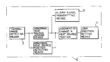
Fig. 5 is a block diagram of a disaster
preventing detection apparatus according to the
invention.
In addition to the thermal image detecting
means 3, the sustaining portion 2 includes an abnormal
heat source ud ing means, an abnormal heat source
Je~e~j~6 /~cL~O~ ~ ~,e~f sO~ ce ~oO~,~Jir~ ~7e~o~
~ position ~dgi~g meansfland an alarm signal transmitting
10 means.
First, the thermal image detecting means 3
detects a thermal image of a person's body, a fire and
so forth. Next, the abnormal heat source j~ ging means
~e~e
and the abnormal heat source position ~idg~*g means
lS judge an abnormal heat source (an intruder, a fire or
the like) and its position~, And, the lens direction
setting means is operated to control the direction of a
lens in the video camera.
Figs. 6A and 6B are diagrams for explaining
2~ the function of the disaster preventing detection
apparatus according to the embodiment of the invention.
Each of the diagrams shows a thermal image and
a visible image and places one upon another.
As indicated by a thermal image in Figs. 6A
25 and 6B, when the existence of an abnormal heat source
which has not existed in the previous stage is
confirmed, a signal is outputted by the alarm signal
; transmitting means.
* ~ ~e~ ze ~ e~ O~ e~ ece
~0O,~ f JD~ ~y ~e ~e~ ~ ~o,~
2~728~7
1 Referring to Fig. 6B, the abnormal heat source
judging means judges a heat source as a fire when the
temperature of the heat source is sufficiently high.
Referring now to Fig. 6A, when the temperature of a heat
source is not sufficiently high, the abnormal heat
source position judging means determines the position of
the heat source, and the lens direction setting means 4
controls the lens direction of the video camera.
Figs. 7A and 7B are structural views showing
one embodiment of the thermal image detecting means 3
according to the invention. Reference numerals 6a to 6e
denote pyroelectric-type thermal detection elements; 6
denotes a group of the pyroelectric-type thermal
detection elements; and 7 denotes a rotational axis.
Fig. 7A illustrates a condition in which the rotational
axis 7 extends in parallel to the pyroelectric-type
thermal detection elements group 6, and Fig. 7B
illustrates a condition in which the rotational axis 7
inclines at an angle ~ from the pyroelectric-type
thermal detection elements group 6. The angle ~ is
determined in accordance with the structure of the
sustaining portion 2 to which the thermal image
detecting means 3 is attached and the preset angle of
detecting field of view.
Next, referring to Figs. 8A and 8B, there will
be described the mechanism to obtain a thermal image by
use of the pyroelectric-type thermal detection elements
group 6. Fig. 8A illustrates a three-dimensional
7 --
,
2072~7
1 visibility angle of a thermal image to be detected, and
Fig. 8B illustrates the detected thermal image. The
pyroelectric-type thermal detection elements group 6
includes five elements which cover the respective
sections of the visibility angle which is divided into
five in the vertical direction.
The pyroelectric-type thermal detection
elements group 6 is used in combination with an optical
lens. The preset visibility angle is narrow in the
horizontal direction so that the horizontal visibility
angle is moved along with rotation of the rotating axis
7. Every time the horizontal visibility angle is moved,
the pyroelectric-type thermal detection elements group 6
measures the temperature, thereby obtaining the two-
dimensional thermal image shown in Fig. 8B.
A pyroelectric-type infrared sensor in general
use is of a so-called bulk shape and includes a sintered
material of a pyroelectric thick film. However, the
bulk-shape sensor involves a problem that the thermal
time constant cannot be decreased and thereby the bulk-
shape sensor is slow in response. Therefore, a
pyroelectric-type thermal detection element including a
pyroelectric thin film of PbTiO3 or the like is employed
so that the time for response can be made about 1/10 of
25 that of the bulk-shape sensor.
By using pyroelectric-type thermal detection
elements including such a pyroelectric thin film in
order to shorten the response time, movement or the like
..,~
2072~7
l of an intruder can be detected highly accurately. Also,
with the pyroelectric thin film, the elements can be
miniaturized.
According to the present invention, as clearly
described heretofore, an abnormal state can be detected
at an early stage through a thermal image which i5
obtained by the group of pyroelectric-type thermal
detection elements, and also, the position of the
abnormal state can be determined so that an intruder can
be caught in the center of the image-processing frame.
Moreover, according to the invention, the
group of pyroelectric-type thermal detection elements
located in one dimension is rotated to thereby detect a
thermal image with a relatively simple structure.
Furthermore, the group of pyroelectric-type
thermal detection elements including the pyroelectric
thin film is used so as to produce effects such as
improving the thermal image response speed and
miniaturizing the elements.
,, _ g _ .
,.~ ,-.. . .
:
.