Note : Les descriptions sont présentées dans la langue officielle dans laquelle elles ont été soumises.
2090761
WASTE DISPOSAL TRAY
FOR AN AUTOMATIC COFFEE MAKER
Back~round of the Invention
The present invention pertains to tray assemblies
for use with beverage brewing devices. More particularly,
the present invention pertains to tray assemblies which
receive and retain a spent brewing material from a beverage
brewing apparatus and extract a liquid portion of the spent
beverage brewing substance.
Beverage brewing devices are commonly used in
high volume applications such as restaurants, catering
organizations and other high volume food production
institutions. A typical beverage brewing apparatus has a
body which positions a funnel below a heated water source.
The funnel contains a beverage brewi~g substance which is
infused with heated water dispensed into the funnel to
produce a brewed beverage. A brewed beverage is drained
from the funnel into a serving decanter positioned
underneath the funnel.
Such a beverage brewing device requires that the
beverage brewing substance be measured and deposited into the
funnel for each batch of beverage produced. Addltlonally,
this actlvlty lnherently requlres the removal of the spent
brewing substance after it has been lnfused wlth hot water and
a brewed beverage produced therefrom. The need to flll the
funnel wlth a beverage brewlng substance and remove the spent
substance from the funnel is extremely labor lntensive and
prone to error due to mismeasurement or fallure to remove the
spent brewing substance from the funnel before produclng
another batch of brewed beverage.
Recently, beverage brewlng devices have been
produced whlch lntroduce a high degree of automation to the
beverage brewing process. Such a device ls shown ln U.S.
Patent 5,134,925, lssued to Bunn, et al, on August 4, 1992.
The devlce shown ln Bunn, et al lncludes an automatlc brewlng
substance dlspenser for dlspenslng a predetermlned amount of
beverage brewlng substance lnto a brewlng chamber. The
brewlng process ls automated lncludlng automatlcally
controlled brewlng, dlspenslng, and chamber cleanlng. After
the brewlng process ls complete, the spent brewlng substance
ls exhausted from the brewlng chamber through an exhaust tube
into a waste collectlon container.
A problem arlses, however, in handllng the spent
brewing substance. The volume of the brewing substance and
waste water requlres frequent periodic removal and dumplng.
In other words, lt would be deslrable to accumulate the spent
brewlng substance from numerous brewlng cycles ln order to
--2--
63632-1362
~o1 6/
reduce the amount of manual labor requlred in servlclng the
brewlng devlce.
Another problem arlses wlth the accumulatlon of
spent brewlng substance such that a large proportlon of the
waste product ls waste whlch ls retalned by the
-2a-
~ 63632-1362
A-
2~90761
brewing substance itself during the brewing process.
Additionally, it is common for brewing devices, such as the
one shown in Bunn et al., to dispense waste water used to
clean the brewing chamber into the common waste collection
hopper. As such, a substantial quantity of water must be
dealt with in disposing of the spent brewing substance.
Attendant with the accumulation of the spent brewing
substance and water is the problem of the weight of the
container used to collect such waste products. Therefore,
it would be desirable to provide a small waste removal
container which drains off the liquid portion of the waste
materials and permits the accumulation of several brew
cycles worth of spent brewing substance.
One possible solution to the waste material
problem that may have been tried is to simply drain all of
the combined spent brewing substance and waste wat~r down a
common drain. However, this solution may not be feasible
in some areas which restrict the amount of material which
can be flushed down a waste sewer along with waste liquids.
Further, the plumbing requirements to flush substantial
quantities of solid materials may not be available or may
be cost prohibitive since they are substantially greater
than those for merely draining water and other liquids.
Another problem that arises with the accumulation
of spent brewing substances in brewing devices is that the
spent brewing substance creates a great deal of steam and
moisture which, if allowed to travel into the brewing
device, may create many problems. For example, when spent
brewing substances are disposed in a brewing basket, the
steam rises off of the substance as the substance cools in
the waste collection tray. Since the trays are positioned
at the bottom of the brewing devices, the steam rising off
of the spent brewing substance rises through the brewing
device. While the brewing chamber is designed to brew
substances, it is difficult to protect the internal
components of the brewing device from the detrimental
2û90761
effects of the rising steam. In particular, when the
brewing device includes a brewing substance dispenser, the
steam may have an extremely detrimental effect on the
brewing substance retained in the substance dispenser. For
example, if ground coffee is retained in the substance
dispenser, the steam may cause the ground coffee to cake
and therefore not be properly dispensed into the brewing
chamber.
As such, it is desirable to provide a tray
assembly which can be inserted into the beverage brewing
device to receive and retain spent brewing substances
and waste water and drain the liquid portion therefrom.
Further, it is desirable to provide a tray which prevents
steam from the spent brewing substance from escaping from
the tray.
Objects and Summary of the Invention
A general object of the present invention is to
provide a tray assembly for collecting moist, spent brewing
substances and waste water from a brewing apparatus and
separating the liquid portion of such waste from the moist
brewing substance.
Another object of the present invention is to
provide a tray assembly which drains a liquid portion of
the moist, spent brewing substance from the tray assembly
so that only a drained brewing substance is retained in the
tray assembly for removal at a later time.
Yet another object of the present invention is to
provide a tray assembly which has a valve assembly which
automatically seals the tray assembly against leakage when
the tray is removed from the brewing apparatus.
--4--
209d761
Stlll another ob~ect of the present lnventlon ls to
provlde a tray assembly whlch senses when the tray is full of
dralned brewlng substance and whlch lndlcates that the tray
must be emptled.
Therefore, thls lnvention seeks to provlde a tray
assembly for use ln recelvlng and retalnlng molst materlal
such as spent brewing substances and the llke from a beverage
brewlng apparatus and separatlng a llquld portlon therefrom,
sald tray assembly comprlslng: a tray body havlng an entry
aperture for recelvlng molst materlal; llquid separatlon means
retalned in said tray body for drawing off llqulds from molst
materlal; and a controllably sealable tray valve assembly
attached to sald tray body and operatlvely engageable wlth a
draln llne assoclated wlth the beverage brewlng apparatus for
dralnlng llqulds from sald tray assembly out of sald tray
body; a flrst area ln sald tray body between sald entry
aperture and sald llquld separatlon means deflnlng a materlal
recelvlng and retalnlng space, and a second area ln sald tray
body between sald llquld separatlng means and sald tray valve
assembly deflnlng a llquld collectlon space; dralned materlal
belng retalned in sald flrst area for later removal and llquld
drawn off of sald materlal collectlng ln said second area;
said liquid separatlon means lncludlng a porous fllter
materlal belng retalned between sald flrst area and sald
second area, openlngs ln sald fllter materlal belng slzed and
dlmensloned for retalnlng molst materlal and passlng llquld
from sald molst materlal therethrough, support means provldlng
structural support of sald fllter materlal and molst and
-- 5
B 63632-l362
2090761
drained materlal accumulated thereon; retalnlng means
includlng a generally horlzontally orlented shoulder portlon
formed along an lnslde surface of sald tray body and multlple
protruslons along an lnslde surface of sald tray body spaced
apart from sald shoulder portlon for recelvlng and retalning
sald fllter materlal between sald shoulder portlon and sald
protruslons.
Thls lnventlon also seeks to provlde ln comblnatlon,
a tray assembly and a beverage brewlng apparatus; sald tray
assembly recelvlng and retalning molst beverage brewlng
materlal and separatlng a llquld portlon therefrom; sald
brewing apparatus lncludlng a brewlng chamber communlcatlng
with an exhaust llne, molst materlal belng flushed from sald
brewlng chamber through sald exhaust llne; sald exhaust llne
termlnatlng ln an entry port communlcatlng wlth sald tray
assembly; sald entry port of sald brewlng apparatus depositlng
molst materlal lnto sald tray assembly; a draln llne
operatively assoclated wlth sald brewlng apparatus for
communlcatlng wlth sald tray assembly for carrylng separated
llquids away from sald tray assembly; sald tray assembly
comprlslng: a tray body, llquld separatlon means retalned ln
said tray body for drawlng off llqulds from molst material
accumulated in sald tray body, and a controllably sealable
tray valve assembly operatively assoclated wlth sald tray body
and operatlvely engaglng sald draln llne for dralnlng llqulds
from sald tray assembly; support means ln sald brewlng
apparatus for supportlng sald tray assembly ln a predetermlned
posltlon in sald brewlng apparatus for communlcatlng wlth sald
- 5a -
63632-1362
B
2090761
draln llne, sald support means lncludlng slde ralls attached
to said brewing apparatus and supportlng shoulders formed ln
the tray body of the tray assembly, sald supportlng shoulder
cooperatlvely engaglng sald slde ralls to support sald tray
assembly ln sald brewlng apparatus; a slope supportlng bracket
of sald support means disposed underneath sald tray body for
supporting sald tray body and guldlng sald tray valve assembly
into engagement wlth sald draln line; a first area ln said
tray body between said entry port and said liquid separation
means communicating with said entry port deflning a material
recelvlng and retaining space; and a second area ln sald tray
body between sald llquld separatlng means and sald valve
assembly communicatlng with sald tray valve assembly deflnlng
a llquld collectlon space; drained materlal ls retalned ln
sald flrst area for later removal and liquld drawn off of
molst materlal and collected ln sald second area.
Thls lnventlon further seeks to provlde ln
comblnatlon, a tray assembly and a beverage brewlng apparatus;
sald tray assembly recelvlng and retalnlng molst beverage
brewlng materlal and separatlng a llquld portlon therefrom;
sald brewlng apparatus lncludlng a brewlng chamber
communlcating with an exhaust llne, molst materlal belng
flushed from sald brewlng chamber through sald exhaust llne;
sald exhaust llne termlnatlng ln an entry port communlcatlng
wlth sald tray assembly; sald entry port of sald brewlng
apparatus deposltlng molst materlal lnto sald tray assembly; a
draln llne operatively assoclated wlth said brewlng apparatus
for communlcating wlth sald tray assembly for carrylng
- 5b -
63632-1362
B
2090761
separated llqulds away from sald tray assembly; sald tray
assembly comprlsing: a tray body, porous fllter material
retalned ln sald tray body for drawlng off llqulds from molst
materlal accumulated ln sald tray body, and a controllably
sealable tray valve assembly operatlvely assoclated wlth sald
tray body and operatlvely engaglng sald draln llne for
dralnlng llqulds from said tray assembly; a first area in sald
tray body between sald entry port and sald porous fllter
materlal communlcatlng with sald entry port deflnlng a
material recelving and retalnlng space; and a second area ln
said tray body between sald porous fllter materlal and sald
valve assembly communlcatlng wlth sald tray valve assembly
deflnlng a llquld collectlon space; retalnlng means for
holdlng said filter materlal ln sald tray assembly; sald
fllter materlal belng retalned between sald flrst area and
sald second area, openings ln sald fllter materlal belng slzed
and dlmensloned for retalning molst materlal and passlng
liquld from sald molst materlal therethrough, support means
providlng structural support of molst and dralned materlal
thereon, sald support means lncludlng a shoulder portlon ln
sald tray body and multlple protruslons spaced apart from sald
shoulder a distance sufflclent to retaln sald fllter materlal
between sald shoulder portlon and sald protruslons; dralned
materlal ls retalned ln sald flrst area for later removal and
llquld drawn off of moist materlal and collected ln sald
second area.
- 5c -
63632-1362
B
2nso7sl
Brief Description of the Drawings
The organization and manner of the structure and
operation of the invention, together with further objects
and advantages thereof, may be understood by reference to
the following description taken in connection with the
accompanying draw~ings, wherein like reference numerals
identify like elements, and in which: .
FIG. 1 is a perspective view of a brewing
apparatus in which the present invention is used and
further showing showing a waste tray assembly of the
present invention positioned in a compartment in a lower
portion of the brewing apparatus;
FIG. 2 is an exploded perspective view of the
waste tray assembly in which a cover and a liquid
separation portion have been removed from a tray body;
FIG. 3 is a cross sectional plan view of the tray
assembly of the present invention taken along line 3-3 in
FIG. 1 showing the tray assembly in engagement with a drain
line exiting from the brewing apparatus and showing the
outline of the brewing apparatus in phantom line;
FIG. 4 is partial fragmentary cross sectional
front view of the tray assembly of the present invention
taken along line 4-4 in FIG. 3 showing support members
which support the tray assembly in the compartment;
FIG. 5 is a cross sectional side elevational view
of the tray assembly of the present invention taken along
line 5-5 in FIG. 1 showing the tray assembly in engagement
with the drain line exiting from the brewing apparatus;
209~761
FIG. 6 is an enlarged partial fragmentary cross
sectional side elevational view of the valve assembly of
the present invention taken along line 6-6 in FIG. 3
showing a valve portion in engagement with a drain line
nipple;
FIG. 7 'is an enlarged partial fragmentary cross
sectional side elevational view of the valve assembly of
the present invention as shown in FIG. 6 in which the valve
portion is disengaged from the drain line nipple and the
tray valve portion is sealed against leakage;
FIG. 8 is an enlarged side sectional view of a
contact assembly as shown in FIG. 5; and
FIG. 9 is an enlarged, cross sectional, side view
of a sealing member which engages an aperture formed in a
cover of the tray assembly to seal the aperture and thus
prevent the escape of steam which rises off of the spent
brewing substance disposed in the tray.
Detailed Description of the Illustrated Embodiment
While the invention may be susceptible to
embodiment in different forms, there is shown in the
drawings, and herein will be described in detail, a
specific embodiment with the understanding that the present
disclosure is to be considered an exemplification of the
principles of the invention and is not intended to limit
the invention to that as illustrated and described herein.
Referring now to the drawings, wherein like parts
are designated by the same reference numerals throughout
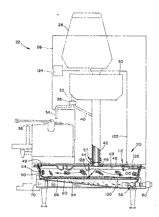
the figures, FIG. 1 shows a tray assembly 20 (in phantom
line) positioned in a beverage brewing apparatus 22. With
reference to FIG. 5, the beverage brewing apparatus 22 has ~-
a body 26 (shown in phantom line) which houses a material -
7--
209~761
-
hopper 28 for dispensing material into a brew chamber 30
where a brewed substance is produced. A dispensing line 32
communicates with the brewing chamber 30 for dispensing a
brewed beverage produced in the brew chamber 30 through a
beverage line 34 into a dispensing decanter 36. During a
cleaning cycle, in which the brew chamber 30 is cleaned
after a brewing c'ycle, a valve 38 on the dispensing line 32
directs waste water through a waste line 40 into a larger
diameter exhaust line 42. The larger diameter exhaust line
42 communicates with the brew chamber 30 for removing the
spent brewing substance therefrom at the end of the brewing
cycle. The exhaust line 42 terminates in an entry port 44
at an end distal the brewing chamber 30. The entry port 44
deposits spent brewing substance and waste water into the
tray assembly 20 through an entry aperture 46 formed
through a cover portion 48 of the tray assembly 20.
With reference to FIG. 2, the tray assembly 20
includes a tray body 50, a liquid separation portion 52 and
the cover 48. The tray body 50 has a tub-like shape with a
bottom surface 54 which slopes downwardly towards a tray
valve assembly 56. A supporting lip 49 is formed around
the inside perimeter of the upper edge of the tray body 50
for supporting the cover 48. The supporting lip 49 is
formed on the inside surface of the tray body 50 and
engages the cover 48 to facilitate the draining of
condensation which may collect on the inside surface 69 of
the cover 48.
A sealing member 57 is attached to the lowermost
end of the exhaust line 42. The sealing member 57 includes
a grommet portion 59 and an enlarged flange portion 61.
The grommet portion 59 forms a seal between the bottom of
the machine 63, through which the exhaust line 42
protrudes, with the flange portion 61 overlying the area of
the bottom of the machine 63 facing the entry aperture 46
formed through the cover portion 48. A sloped side 65 of
2090761
the flange portion 61 forms an interference fit between the
sealing member 57 and the cover 48.
The cover 48 is formed with a degree of spring or
flexibility to facilitate the interference fit between the
sealing member 57 and the cover 48. In other words, when
the cover 48 is positioned in the supporting lip 49 of the
tray 50, there is a degree of deflection permitted so that
the cover 48 may be depressed slightly towards the bottom
54 of the body 50. When the tray assembly 20 is inserted
into the brewing apparatus 22, the sealing member presses
the cover 48 slightly downwardly so that a portion 67 of
the sealing member 57 projects down into the entry aperture
46 formed through the cover 48. This interference fit
between the sealing member 57 and the cover 48 prevents
moisture from escaping from the tray assembly 20 when the
spent brewing substance is disposed therein. Any moisture
which evolves from the brewing substance disposed in the
tray assembly 20 rises and condenses on an inside surface
69 of the cover 48 and eventually collects and drains back
into the tray body 50. The cover 48 and the interference
fit with the sealing member 57 prevents moisture from
infiltrating the brewing apparatus 22 positioned above the
tray assembly.
The liquid separation portion 52 includes a
filter material 60. The filter material 60 as illustrated
has openings 62 formed therethrough which are small enough
to allow the liquids to pass through but not the brewing
substances. Additionally, a disposable filter liner 64 can
be placed over the filter material to improve the ease and
efficiency in removing the spent brewing substances
disposed therein. For example, when spent brewing
substances are disposed into the filter liner 64, when the
tray assembly 20 becomes filled, the tray assembly 20 may
be removed from the brewing apparatus 22 and merely the
filter liner 64 with the drained brewing substance therein
removed for disposal. Such a filter liner 64 would
2~9076~
eliminate the need to rinse the filter material 60 which
otherwise could remain inside of the brewer body 50.
The filter material 60 spans the tray body 50 and
is supported on top of a shoulder portion 66 and beneath a
series of protrusions 68 which are spaced away from the
shoulder portion~66. The filter material 60 is retained on
top of the shoulder portion 66 by the protrusions 68 in a
secure yet removable manner.
The tray assembly 20 is supported in the brewing
apparatus 22 by side support members 70. The support
members support a side edge 72 of the tray body 50. In
such a supported position, the bottom surface 54 maintains
a slope in order to promote the flow of liquids towards the
tray valve assembly 56.
As shown in FIG. 5, spent brewing substances and
waste liquids are deposited through the exhaust line 42
onto the liquid separation portion 52 of the tray assembly
20. Once deposited thereon, the liquid portion of the
spent brewing substance and waste liquid drains through the
liquid separation portion 52 onto the bottom portion 54 for
draining out through the tray valve assembly 56.
FIGS. 6 and 7 are referred for the purpose of
elaborating on the tray valve assembly 56 as introduced
hereinabove. Included in the tray valve assembly 56 is a
grommet 74 with an aperture 76 extending therethrough. The
grommet 74 sealably extends through a side of the tray body
50. Biased stopper means 78 seals the bore 76 when the
tray is disengaged from a drain line 80, which drain line
80 is connected to the body 26 of the brewing apparatus 22.
A conduit member 82 is attached to the drain line 80 and is
slidably engagable with the bore 76. When the conduit 82
is inserted through the grommet 74, a front end 90 presses
against and displaces the biased stopper means 78. In
order to promote engagement, an outside portion 84 of the
--10--
20~0761
grommet 74 has a conduit receiving recess 86 formed therein
to guide the front end 90 of the conduit member 82 into
engagement with the grommet 74.
When the tray 20 is inserted into the brewing
apparatus 22, the position of the side support members 70
help to align the' tray 20 so that the front end 90 of the
conduit 82 engages the grommet 74. Once the conduit 82 is
engaged with the grommet 74, the front end 90 displaces the
biased stopper means 78 to allow liquid to flow from the
tray assembly 20. FIG. 6 provides a view of the tray
assembly 20 engaged with the drain line 80 such that liquid
(as represented by arrows 92) may flow through the conduit
member 82 into the drain line 80.
The biased stopper means 78 include a spherical
body 94, a biasing member or spring 96, and a retaining
member 98. An inside portion 100 of the grommet 74 has a
stopper receiving recess 102 formed therein for
cooperatively receiving the spherical body 94. When the
spherical body 94 is engaged with the stopper receiving
recess 102, the bore 76 and the grommet 74 are sealed and
no fluids will leak from the tray assembly 20. The
spherical body 94 is retained in engagement with the
stopper receiving recess 102 by the biasing means 96.
With reference to FIG. 7, the biasing means 96
impose forces (as represented by arrow 104) on the
spherical body 94 to retain the spherical body 94 in
engagement with the stopper receiving recess 102. The
retaining member 98 provides a backstop for the biasing
member 96. When the tray is moved (as represented by arrow
106) into engagement with the conduit member 82, the forces
(represented by arrow 108) are transferred from the conduit
member 82, which is stationary relative to the brewing
apparatus, to compress the biasing member 96 against the
retaining member 98. Compression of the biasing member 96
disengages the spherical body 94 from the stopper receiving
2090761
recess 102. Apertures 110 are formed through the sides of
the front end 90 of the conduit member 82 for allowing
fluids 92 to flow therethrough and into the conduit member
82. As shown in FIG. 7, the apertures 110 are not exposed
until, as shown in FIG. 6, the spherical body 94 is
disengaged from the stopper receiving recess 102 and the
conduit 82 protrudes from the bore 76.
Sensor means or a sensor assembly 112 is attached
to the cover 48 and a cooperatively abutting portion 114 of
the brewing apparatus 22. The sensor assembly 112 includes
a tray contact 116 mounted to the tray assembly 20 and a
mating contact 118 mounted to the portion of the brewing
apparatus 114. The tray contact as shown in FIG. 8 is
attached to the cover 48 of the tray assembly 20 and has a
stud portion 120 which extends a distance into the tray
body.
As shown in FIGS. 2 and 3, there are three tray
contacts 116 included in the sensor assembly 112. Two of
the three tray contacts provides information on the
positioning of the tray assembly 20 in the brewing
apparatus 22. Contacts 116a, 116b are dedicated as
positioning contacts 116a, 116b and are tied with a common
strap. When the tray 20 is properly positioned, the
contacts 116a, 116b complete the circuit with corresponding
mating contacts 118a, 118b (not shown).
The other tray contact 116c cooperatively engages
a corresponding mating contact 118c. When the level
sensing contacts 116a, 116b are engaged with the
corresponding mating contacts 118a,118b, an open circuit is
created between the contacts 116a,116b and contact 116c
over a control line 122 to a control unit 124. With
reference to FIG. 8, when the level of matèrial and/or
liquid (represented by line 126) reaches a predetermined
level, the material immerses the stud portions
120a,120b,120c of the corresponding tray contacts
-12-
2090761
116a,116b,116c, thereby shorting the circuit between the
two contacts 116a,116b and through moist material to
contact 116c. Thus, the contacts 116a,116b,116c indicate,
over control line 122 to the control unit 124, that the
level has reached a predetermined height. The control unit
124 in turn will provide a form of indication to an
operator that the' tray assembly 20 must be emptied.
An example of the control unit 124 indication
include energizing a light or some other warning that the
tray assembly 20 is full. Additionally, the control unit
124 can be programmed to prevent further brewing until the
tray assembly 20 is emptied. In this regard, when an
operator tries to initiate a brew cycle with a full tray
assembly 20, the control unit 124 controls the brewing
apparatus 22 to prevent further brewing. Once the tray
assembly 20 has been removed and emptied, the level of the
material or fluids therein drops below the predetermined
high level 126 to permit further brewing by the brewing
apparatus 22.
In use, the present invention comprises the tray
assembly 20 including the liquid separation, level sensing,
position sensing, and controllable drain valve features.
The tray assembly 20 is inserted into the brewing apparatus
22 to receive and retain spent brewing substances exhausted
by the brewing apparatus 22. When the tray assembly 20 is
properly positioned in the brewing apparatus 22, the
positioning contact 116a contacts a corresponding mating
contact 118a to indicate that the tray assembly 20 is
properly engaged with the conduit member 82 attached to the
drain line 80. The side support member 70 supports the
tray assembly 20 while positioned in the brewing apparatus
22 to maintain the bottom surface 54 of the tray body 50 in
a sloped orientation toward the tray valve assembly 56.
When the tray assembly 20 is inserted into the
brewing apparatus 22, the sealing member 57 slightly
-13-
2090761
-
downwardly deflects the cover 48 towards the bottom 54 of
the tray body 50. The cover 48 has a degree of
yieldability. When the sealing member 57 is positioned in
engagement with the aperture 46, a portion 67 of the
sealing member 57 extends into the aperture 46 to form an
interference fit between the sealing member 57 and the
cover 48. Since the cover 48 is slightly deflected
downwardly by the sealing member 57, a tighter seal is
formed between the cover 48 and the supporting lip 49. The
seal between the cover 48 and the lip 49 as well as the
interference fit between the sealing member 57 and the
aperture 46 prevent steam and other moisture from escaping
and infiltrating the brewing apparatus 22.
Once the tray assembly 20 is positioned in the
brewing apparatus 22, the entry port 44 is coincident with
the entry aperture 46 through the cover 48. Thus
positioned, the tray assembly 20 is ready for receiving and
retaining spent beverage brewing substances from the
brewing apparatus through the exhaust line 42. When
brewing substances are deposited into the tray body 50,
they are received in the receiving and retaining space or
first area 128 defined between the entry aperture 46 and
the liquid separation portion 52. When the spent brewing
substance is emitted from the entry port 44, the material
is generally in a slurry form having both liquid and solid
components. The slurry form of the spent brewing substance
spreads out over the liquid separation portion 52 in a
generally even, self-leveling manner. Subsequent emissions
from the brewing apparatus 22 also generally flow over the
prior drained material in a generally even manner.
The generally evenly distributed spent brewing
substance is separated into liquid and solid components by
the liquid separation portion 52. The liquid portion
drains through the filter material 60 of the separation
portion 52 and flows into the liquid collection space 130
defined between the liquid separation portion 52 and the
-14-
2090761
bottom surface 54. As the liquid collects in the
collection space 130, it drains from the tray assembly 20
through the tray valve assembly 56 into a drain line 80.
The tray valve assembly 56 includes the grommet
74 mounted in the side of the tray body 50 and biasing
stopper means 78 'which plug the aperture 76 of the ~.omll.ct
74 to prevent leakage from the tray assembly 20 when it is
disengaged from the conduit member 82. When the tray
assembly 20 is inserted into the brewing apparatus 22, the
front end 90 of the conduit member 82 pushes against the
spherical body 94 of the biased stopper means 78 to
compress the biasing member 96 against the retaining member
98 thereby disengaging the spherical body 94 from the
stopper recess 102 in the grommet 74. The apertures 110
formed through the sides of the front end 90 allow fluid to
flow from the tray body 50 through the conduit member 82
and out through the drain line 80.
As the spent brewing material accumulates in the
tray assembly 20, the level of the material rises to a
predetermined full tray level 126. When the full tray
level 126 is attained, the stud portions 120 of the level
sensing contacts 116b, 116c are immersed and complete a
circuit therebetween to indicate that the high level 126
has been attained. The completed circuit is sensed by the
controller 124 over the control line 122 providing
indication to a user and/or controllably stopping future
brewing cycles.
While a preferred embodiment of the present
invention is shown and described, it is envisioned that
those skilled in the art may devise various modifications
of the present invention without departing from the spirit
and scope of the appended claims. The invention is not
intended to be limited by the foregoing disclosure.