Sélection de la langue

Search

Sommaire du brevet 2091520 

Énoncé de désistement de responsabilité concernant l'information provenant de tiers

Une partie des informations de ce site Web a été fournie par des sources externes. Le gouvernement du Canada n'assume aucune responsabilité concernant la précision, l'actualité ou la fiabilité des informations fournies par les sources externes. Les utilisateurs qui désirent employer cette information devraient consulter directement la source des informations. Le contenu fourni par les sources externes n'est pas assujetti aux exigences sur les langues officielles, la protection des renseignements personnels et l'accessibilité.

Disponibilité de l'Abrégé et des Revendications

L'apparition de différences dans le texte et l'image des Revendications et de l'Abrégé dépend du moment auquel le document est publié. Les textes des Revendications et de l'Abrégé sont affichés :

  • lorsque la demande peut être examinée par le public;
  • lorsque le brevet est émis (délivrance).
(12) Demande de brevet: (11) CA 2091520
(54) Titre français: RECEPTACLE A SOUPAPE DE SORTIE
(54) Titre anglais: CONTAINER HAVING A VALVE CONTROLLED OUTLET
Statut: Réputée abandonnée et au-delà du délai pour le rétablissement - en attente de la réponse à l’avis de communication rejetée
Données bibliographiques
(51) Classification internationale des brevets (CIB):
  • B65D 47/26 (2006.01)
  • B65D 47/20 (2006.01)
(72) Inventeurs :
  • HUFFMAN, TERRY (Etats-Unis d'Amérique)
  • NOST, AAGE (Etats-Unis d'Amérique)
(73) Titulaires :
  • H & N ENTERPRISES, INC.
(71) Demandeurs :
  • H & N ENTERPRISES, INC. (Etats-Unis d'Amérique)
(74) Agent: GOWLING WLG (CANADA) LLP
(74) Co-agent:
(45) Délivré:
(22) Date de dépôt: 1993-03-11
(41) Mise à la disponibilité du public: 1994-09-12
Licence disponible: S.O.
Cédé au domaine public: S.O.
(25) Langue des documents déposés: Anglais

Traité de coopération en matière de brevets (PCT): Non

(30) Données de priorité de la demande: S.O.

Abrégés

Abrégé anglais


ABSTRACT
A dispensing container for motor oil includes a conventional oil
container which has an upwardly tapered top surface. A valve at
the outlet and a valve stem is axially disposed in the container.
The valve and valve stem have a bellowed actuating member disposed
in an open cavity at the container bottom, which when depressed,
opens the valve. A safety stem is provided on the valve stem which
engages the tapered top surface for preventing the valve and valve
stem from falling out of the container after the container has been
opened and inverted.

Revendications

Note : Les revendications sont présentées dans la langue officielle dans laquelle elles ont été soumises.


CLAIMS
1. A dispenser for dispensing liquids, comprising:
a) a container having an outlet opening;
b) a valve stem disposed in said container, said valve
stem at a first end, having a valve which normally closes said
outlet opening and at a second end, being connected to the
container; and
c) means for flexibly connecting said second end to the
container at a location remote from said outlet opening and having
interior portions thereof which hold said second end of said valve
stem, said flexibly connecting means serving as an actuator, when
moved, for moving said valve via said valve stem, to a position in
which the outlet opening is unobstructed by said valve to permit
dispensing from the container.
2. The dispenser of Claim 1, further including means for
preventing said valve and valve stem from falling out of the
container after the container has been opened and inverted, said
means comprising a safety stem angularly disposed on said valve
stem in a direction toward an upwardly tapered top wall of the
container and spaced therefrom when the valve is in a closed
position, such that upon moving the valve to an open position, the
safety stem engages said tapered top wall and prevents said valve
and stem from falling out of the container when the container is
inverted.

3. The dispenser of Claim 1, wherein said second end of said
valve stem is located within a recess in said container, said
recess being outwardly open at an access opening.
4. The dispenser according to Claim 3, further comprising
a seal disposed over said access opening.
5. The dispenser according to Claim 4, further comprising
a pull tab on said seal.
6. The dispenser of Claim 1, wherein said means for flexibly
connecting said second end of said valve stem to said container
comprises a bellows formed at said location.
7. The dispenser according to Claim 6, further comprising
grooves on said second end of said valve stem which are engaged by
interior portions of said bellows.
8. The dispenser according to Claim 1, further comprising
a threaded cap and threads surrounding said outlet opening to
receive said cap.

Description

Note : Les descriptions sont présentées dans la langue officielle dans laquelle elles ont été soumises.

BACKGROUND
It has become customary for mokorists to purchase containers of
motor oil in singular numbers, and maintain proper oil level in the
crank case by adding oil when necessary. If it were necessary to
add oil when no funnel or other tools were available, it was common
to spill oil on the motor, or on your hands. In accordance with
the present invention, we are able to avoid this spilling, since
after removing the threadably engaged closure cap, the secondary
closure will prevent oil from escaping the container while it is
being turned upside down, and placed in the oil filler opening of
the engine. The oil will only flow into the engine after the
secondary closure is opened, thus preventing ~he chance of any
hazardous and unwanted spill. Funnels or other tools will not be
needed to dispense oil into the motor.
SUMMARY
The present invention relates to a new and ~pill proof way of
dispensing oil and other liquids using a conventional shaped
container, and further using a threadably engaged closure cap about
, _ ,, _ _ _ _ _ . _ _ _ . _ _ _ _ . _ . . . _ _, .. _ .. _ _ .. _ _ _ _ _ _ _ . . .. . _ _ _ . _ _ _ _ _ . _ _ _ _
the container opening, a secondary closure under the cap,
functioning as a plug shaped valve head attached to a push rod
extending from the top to ~he bottom of the container. This valve
can be extended out of the opening, thereby allowing for free flow
of the liquids from the contaîner, or by having a twist top

container neck with slated openings inside, so when the slats are
aligned, the fluid will flow from the container.
BRIEF DESCRIPTION OF THE DRAWINGS
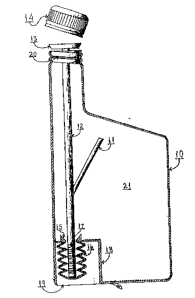
Figure 1 is a full cut-a-way vertical side view of a first
embodiment in which the internal hull of the container is exposed.
Figure 2 is a bottom view of the container of Figure 1. Figure 3
is a full cut-a-way vertical side view of a second embodiment in
which the internal hull of the container is exposed, showing two
sections of the container, and where they are connected. Figure
4 is an enlarged, fragmented, vertical sectional view taken from
the view of Figure 3, as indicated by the circle, showing how the
two sections are connected. Figure 5 is a top view of Figu~e 3,
æhowing the internal opening, or slats~ of the twist top container
neck, and showing how the quadrant shape openings can be twisted
into position to open and close by aligning the two openings so a
through passage from the bottom of the container through the neck
is opened up.
DESCRIPTION OF THE PREFERRED EMBODIMENT
_ _ _ _ _ _ _ _ _ _ _ _ _ _ _ _ _ _ _ _ _ _ _
In accordance with the preferred embodiment of the present
invention, attention being directed to Figure 1 and Figure 2 of the
drawings, the container generally designated 10 has the shape of
a conventional oil container with an upwardly tapered top surface.
Element 11 is a safety stem attached to valve stem 12, and helps
to prevent the valve ~em 12 from falling out when pouring oil from

the container by its engagement with the internal side of the
upwardly tapered top surface of the container. Element 13 is a
closure plug shaped valve head mounte~ on valve stem 12 that opens
up the container outlet. Element 14 is a closure cap adapted to
be threadably engaged about the top. Specifically, the threaded
engagement is provided by means of threads 20 formed about the
periphery of the top of the neck of the container, and the closure
cap 14 being provided with internal matching threads. The internal
bottom surface of the container adjacent valve stem 12 has an
opening with a tapered guide 15, to assist in the insertion of the
valve stem 12 into the accordion type bellows 16. Bellows 16 can
be depressed so the valve stem 12 will push the valve plug 13 out
and opens up the container outlet for the free flow of oil.
Grooves 17 are provided on valve stem 12, to hold the valve stem
in place by the inside edges of the accordion type bellows 16,
acting as a back up safety feature to prevent the valve stem and
the valv~ plug 13 from falling out if by accident the safety stem
11 was missing. The whole assembly of the valve plug 13, valve
stem 12, safety stem 11, and accordion type bellows 16 is made of
a ~lexible plastic, otherwise it cannot be inserted into the
container, or manipulated to open up the valve. Wall 18 at the
container bottom creates a cavity in which the accordion type
bellows 16 are housed and protected from damage. A plastic seal
19 with pull tab is glu~d onto the bottom of the container 10 to

cover up the cavity. The term "conventional oil cont~iner" in the
initial description of the shape of the cont~iner may be used in
a comprehensive sense, and i5 intended to encompass containers
having round or circular walls, as well as those with plainer
panels and rectangular, cylindrical configurations.
DESCRIPTION OF ALTERNATE PREFERRED EMBOI)IMENT
Attention is now being directed to Figure 3, 4, and 5, where we can
see that the container 10, which has similar shape to that of
Figure 1, is provided with a slightly longer neck, 27, and a
different valve as a secondary closure container shown in Figure
1. The hull of the container 21 is filled with oil, and the oil
is held in place by a-closure cap 14, and a secondary valve 24, 25.
The container will remain closed until the closure cap 14, and the
secondary closure valve 24, 25 are opened. The secondary closure
valve 24, 25 can be opened by twisting the handle 22, which is
attached to the neck, 27. By that, the neck 27 creates an opening
through which oil can freely flow out of the container. Figure 4
shows a large, fragmented circle 23 which within, depicts how the
portion 27 is snapped onto the main container 10, and creates a
tight fit seal, 26, between the two component parts. One side, or
a portion of the oil escapes the container by monitoring the fluid
level in the container. By monitoring the fluid level in the
container 21, the f 13W of oil from the container can be stopped
after dispensing a desired amount, 1/2, 1/4, etc., by twisting the

handle 22, so the swivel neck turns and closes the valve 24, 25 by
altering the position of the openings 24, 25 so they no longer are
aligned, and thereby closing off the passage for free flow of oil
from the hull of the container, 21. Having fully described this
invention, I hereby reserve the benefit of all changes in form,
arrangement, order, or use of all parts and materials, as it is
obvious that many minor changes may be made to the design and
arrangement of the individual component parts, without departing
from the spirit of the invention.

Dessin représentatif
Une figure unique qui représente un dessin illustrant l'invention.
États administratifs

2024-08-01 : Dans le cadre de la transition vers les Brevets de nouvelle génération (BNG), la base de données sur les brevets canadiens (BDBC) contient désormais un Historique d'événement plus détaillé, qui reproduit le Journal des événements de notre nouvelle solution interne.

Veuillez noter que les événements débutant par « Inactive : » se réfèrent à des événements qui ne sont plus utilisés dans notre nouvelle solution interne.

Pour une meilleure compréhension de l'état de la demande ou brevet qui figure sur cette page, la rubrique Mise en garde , et les descriptions de Brevet , Historique d'événement , Taxes périodiques et Historique des paiements devraient être consultées.

Historique d'événement

Description Date
Inactive : CIB de MCD 2006-03-11
Le délai pour l'annulation est expiré 1996-09-11
Demande non rétablie avant l'échéance 1996-09-11
Réputée abandonnée - omission de répondre à un avis sur les taxes pour le maintien en état 1996-03-11
Inactive : Demande ad hoc documentée 1996-03-11
Demande publiée (accessible au public) 1994-09-12

Historique d'abandonnement

Date d'abandonnement Raison Date de rétablissement
1996-03-11
Titulaires au dossier

Les titulaires actuels et antérieures au dossier sont affichés en ordre alphabétique.

Titulaires actuels au dossier
H & N ENTERPRISES, INC.
Titulaires antérieures au dossier
AAGE NOST
TERRY HUFFMAN
Les propriétaires antérieurs qui ne figurent pas dans la liste des « Propriétaires au dossier » apparaîtront dans d'autres documents au dossier.
Documents

Pour visionner les fichiers sélectionnés, entrer le code reCAPTCHA :


Pour visualiser une image, cliquer sur un lien dans la colonne description du document. Pour télécharger l'image (les images), cliquer l'une ou plusieurs cases à cocher dans la première colonne et ensuite cliquer sur le bouton "Télécharger sélection en format PDF (archive Zip)" ou le bouton "Télécharger sélection (en un fichier PDF fusionné)".

Liste des documents de brevet publiés et non publiés sur la BDBC .

Si vous avez des difficultés à accéder au contenu, veuillez communiquer avec le Centre de services à la clientèle au 1-866-997-1936, ou envoyer un courriel au Centre de service à la clientèle de l'OPIC.


Description du
Document 
Date
(aaaa-mm-jj) 
Nombre de pages   Taille de l'image (Ko) 
Revendications 1994-09-11 2 130
Dessins 1994-09-11 3 185
Abrégé 1994-09-11 1 50
Description 1994-09-11 5 318
Dessin représentatif 1998-08-19 1 24
Taxes 1995-02-22 1 41
Correspondance de la poursuite 1993-06-14 1 25
Courtoisie - Lettre du bureau 1994-01-10 1 34