Note : Les descriptions sont présentées dans la langue officielle dans laquelle elles ont été soumises.
WO92/~7718 2~3S2~ PCT/USgl/07
.:
8TR~CTUR~S FOR 8CR~EN
TEN810NING AND PRINTING
Fiel~ of the Invention
The present invention relates to an improvement in
screen tensioning and printing frames. The present
invention is directed to permitting the frame to tension
the screen to ultra high tensions. In particular, the
invention relates to the end plug portion of the roller
member of a screen printing frame.
.:' ,
Bao~round of the Invention
The present invention is generally contemplated to
be used along with the screen ~tensioning and printing
frame members as described in U.S. Pat. No. 4,525,909.
~owever, other members for a screen printing frame are
also contemplated for use along with the present
invention. Other examples of roller members and frames
are described in U.S. Pat. Nos. 3,908,293: 4,430,815; and
;4,430,814.
.~An apparatus for screen tensioning and printing
generally comprises a frame typically having a plurality
of roller members coupled together by corner members.
The corner members support the rollers for rotation about
their longitudinal axes. Each roller includes a
longitudinally extending channel on its periphery so as
to receive means to retain an edge portion of a screen
~`~fabric in the channel. Means is associated with each
corner member for locking each roller in a predetermined
W092/07718 ~0 9 ~ 2 ~ 8 PCT/US91/o71~
-2-
rotative position so that the desired tension may be
applied to the screen fabric. Moreover, means is
provided on the end of each roller for causing the
rotation of the roller about its longitudinal axis and
creating the tension in the screen.
The roller portion of the printing frames generally
includes an end plug positioned within a hollow extruded
roller. The end plug generally includes an internal
thread means for receiving the locking means for
attaching the roller to the corner members. The external
surfaces of the end plug generally form or include a hex
nut type structure which may be engaged by a wrench or
the like. The wrench member creates a torque about the
longitudinal axis of the roller member, rotating the
roller and tensioning the screen.
The present invention generally relates to the use
of ultra high tension in the screen portion of the
printing frame. An improved screen material for and
method of screen printing is described in copending
application Serial No. 07/592,081, filed October 3, 1990.
However, known fabric or screen materials may also be
utilized. Moreover, the support structures for a roller
member of a screen tensioning and printing frame are
contemplated to be utilized along with the present
invention. Such support structures are described in U.S.
-- Pat. No. 4,345,390.
-- The disclosure of each of the above-referenced
patents and applications is herein incorporated by
reference.
; 8ummary of the Invention
The present invention generally comprising hex nut
engagement surfaces of the end plug that are elongated in
an axial direction along the longitudinal axis of the
roller. Moreover, a corresponding surface width of the
wrench member associated with the hex nut of the roller
WO92/07718 ~ u ~ ~ 2
-3-
'.
member is contemplated. The combination of the elongated
hex nut surfaces and the wrench member creates sufficient
contact surface area so as to permit the ultra high
tension within the screen member without failure of the
end plug material.
The prior art end plugs were made of a relatively
soft material (soft as compared to a stainless steel or
the like) in which, although the effective size of the
nut was substantially greater than the metal nut members
known in the art, such material was of insufficient sheer
and tensile strength to permit the tensioning as
contemplated without an associated failure.
~rief Description of the Drawinqs
For the purpose of illustrating the invention, there
is shown in the drawings a form which is presently
- preferred; it being understood, however, that this inven-
tion is not limited to the precise arrangements and
instrumentalities shown.
Figure 1 shows a portion of a frame for tensioning
a screen or fabric material for use in screen printing.
Figure 2 shows an exploded view of a roller member
and end plug as contemplated by the present invention.
Figure 3 shows an axial cross-section of the end
plug and roller combination illustrated in Figure 2.
Figure 4 shows a radial cross-section of the end
plug illustrated in Figures 2 and 3.
Figure 5 shows an exploded view of an alternate
embodiment of a roller and end plug combination as con-
templated by the present invention.
Figure 6 is an axial cross-section of the end plug
and roller member illustrated in Figure 5.
Figure 7 is a radial cross-section of the end plug
illustrated by Figures 5 and 6.
Figure 8 is a second radial cross-section of the end
plug illustrated in Figures 5-7.
WO92/07718 PCT/US91/071~
2~2~8 -4-
Detailed Description of the Invention
In the drawing where like numerals indicate like
elements, there is shown a screen tensioning and printing
frame which is generally referred to by the numeral 10.
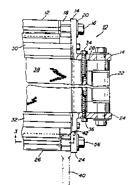
In Figure 1, there is shown only a portion of frame 10.
; The frame 10 generally includes a series of rollers,
three of which being shown in partial view. The first
roller 12 is attached to a corner member 14 by means of
a bolt 16 which engages internal threads (not shown in
Figure 1) within an end plug 18. End plug 18 is inserted
within the first roller member 12. A washer 20 is
positioned between the head of bolt 16 and the corner
member li to provide a bearing surface upon torquing the
bolt 16 into the threads of the end plug 18.
15Attached to the corner member 14 is a second roller
22. The first roller 12 and second roller 22 are
generally perpendicular to one another. The second
roller 22 is of substantially the same construction as
the first roller 12. The opposite end of the second
- 20 roller 22 is attached to a second corner member 24.
Attached to the second corner member is a third roller
member 26~. The opposite ends of first roller 12 and
third roller 26 are also attached to respective corner
members (not shown) and include a fourth frame member,
which may or may not be a fourth roller member tnot
shown).
Associated with each roller 12, 22 and 26, as
illustrated, is a box beam or support structure. The box
beams are generally contemplated to be made in accordance
with the above-referenced U.S. Pat. No. 4,345,390. For
illustration purposes, in Figure 1, the box beam 28 is
illustrated in cross-section adjacent to the second
roller member 22. Box beams 30 and 32 are also
illustrated in association with roller members 12 and 24,
respectively. Box beam 28 is attached to the corner
member 14 by means of bolt 34. The opposite end of box
WO 92/07718 h ~ 2 4 8 PCI`/US91/07164
--5--
beam 28 is attached to corner member 24 by a second bolt
36. Box beams 30 and 32 generally include a similar-type
structure.
A screen material 38 is attached at adjacent edges
to the respective roller members 12, 22 and 26,
respectively. The screen material as contemplated by the
present invention may be made in accordance with Applica-
tion Serial No. 07/592,081, filed October 3, 1990, or as
generally known in the art. The tension in the screen
material is generally created by the rotation of the
rollers 12, 22 and 26, respectively, about their longi-
tudinal axes. The tension is maintained by locking the
rollers at a predetermined rotated position by means of
the bolt 16. Means may be provided for incremental
adjustment of the relative end-to-end position of the
roller members as in accordance with Application Serial
No. 07/403,544, filed September 6, 1989. This
' application is herein incorporated by reference.
A wrench 40 is shown engaged with the surfaces of
end plug 42 associated with roller member 26 attached to
corner member 24. The wrench 40 is generally
contemplated to cause the rotation of the roller member
26 about its longitudinal axis so as to create tension in
the screen material 38. The construction of the end plug
42, as well as end plug 18 and those associated with
roller member 22, will be discussed with respect to
Figures 2-8 below.
Figures 2, 3 and 4 generally show one embodiment of
an end plug and roller member as contemplated by the
present invention. In Figure 2, there is illustrated a
roller 26 and its associated- end plug 42. The roller
generally includes an elongated locking channel 44 on the
periphery thereof. The internal surfaces of the hollow
roller 26 include a series of ribs 46 which project
radially inwardly at various positions. The roller
members are generally contemplated to made of an aluminum
WO92/07718 PCT/US91/071~
2 ~a'~48
-6-
material by an extrusion process. Rib members 46 serve
to stiffen the roller and fixedly couple the end plug to
the roller to prevent slippage. The locking channel 44
is preferably made in accordance with U.S. Pat. No.
4,525,909.
The end plug 42 is formed such that a portion
thereof fits within the hollow portion of the roller 26.
The end plug 42 generally includes a series of slots 48
which are adapted to receive ribs 46 of the roller 26.
Moreover, a flat or engagement surface 50 is provided to
: permit the end plug 42 to fit within the roller. Surface
50 is generally positioned within the roller adjacent to
the internal surfaces which form the locking groove 44.
At the opposite end of the plug member 42 is a hex nut
arrangement 52. The hex nut 52 is exposed when the end
plug 42 is placed within the hollow of roller member 26.
Hex nut 52 provides a series of engagement surfaces which
when engaged by wrench 40, or the like, can cause the
roller to rotate about its longitudinal axis.
As illustrated in Figure 3, positioned within the
hollow portion of the end plug 42 is a nut 54. Nut 54,
" also illustrated in Figure 4, is hexagonal shaped and
fits within a corresponding channel within the end plug
42. The nut 54 is generally adapted to receive bolt 56
so as to lock the roller 26 to the corner member 24 and
to define the predetermined rotated position of the
roller 26. The engagement between the end plug 42 and
the internal surfaces of roller 26 is generally contem-
plated to seal the internal surfaces of the roller. The
engagement between bolt 56 and the nut 54 is also
intended to seal the passageway through the nut 54.
The end plug 42, as generally contemplated by the
present invention, may be made by any material as
desired. However, in viewing weight and cost
considerations, a plastic-type material is generally
preferred. The use of a plastic- or nylon-type material
W092/07718 PCT/US91/071
7~ ~9 ~
for end plugs is known. However, the use of this type
material generally limits the tension that may be applied
to a screen, since the engagement between the wrench,
such as wrench 40, and the end plug 42 may be unable to
provide sufficient torgue without failure of the hex nut
portion 52. It is also contemplated that an aluminum
material or a zinc material may be utilized. The inven-
tion may also include a steel end plug, if desired.
The preferred material as contemplated by the
present invention is a nylon 6/6 material such as the
THERMOCOMP (registered trademark) RF series as
manufactured by LNP Engineering Plastic. The preferred
material is identified by the Serial No. RF-100-10 and
includes a 50% glass full content. This material has an
overall specific gravity of approximately 1.57 and a
specific volume of 17.6 cubic inches per pound. The
tensile strength is approximately 32,000 psi. The
tensile elongation of the material is approximately 2% to
3% with a flexural strength of approximately 46,500 psi.
The flexural modulus is 2,200,000 psi, and the compres-
sive strength is approximately 27,000 psi. The shear
strength is approximately 13,300 psi. Its Izod impact
strength in foot pounds per inch is approximately 3.3 for
a notched ~" x ~" bar and 20 for an un-notched ~" x ~"
bar. The Rockwell hardness, as determined by ASTM method
-D786, is R121/M100. Other suppliers of this type
material are also contemplated, such as DuPont and Adell
Plastics Inc. of Baltimore, Maryland. Certain variations
in the tensile strength may be incorporated into this
material as the subject of its glass content and/or its
amount of virgin nylon utilized. Lower glass content may
also be utilized if the desired strength characteristics
are maintained.
WO92/07718 ~ PCT/~S91/071~
2 ~ 9 ~ ~ ~ 8 -8-
A number of embodiments are contemplated by the
present invention. These embodiments particularly relate
to the outside diameter of the roller and the desired
tension in the screen. However, it is contemplated that
tensions to approximately lO0 newtons per centimeter are
possible. An important dimension with respect to the
present invention is the axial length of the flat
surfaces of the hex nut. Because of the amount of toraue
that is being applied by the wrench 40 and the material
used to form the end plug, the length of these surfaces
generally determines the overall strength of the hex. It
should be noted that the length and overall position of
the flat surfaces from the longitudinal axis of the
roller is generally unrelated to the shear strength of
the threads within the nut 54. It is generally contem-
plated that the number of threads required to lock the
~- roller in its predetermined rotated position by means of
bolt 56 will not need to be substantially increased as a
result of the increase in tension in the screen. Mani-
festly, the present invention does not particularly
relate to the number of threads or the size of the nut
54.
The following is a chart of the variation in the
axial length of the flat surfaces of the hex nut portion
of the end plug in the prior art as compared to that con-
templated by the present invention. These figures are
identified as a function of the diameter of the roller
members.
Roller Prior Hex Improved Hex
30DiameterAxial Lenqth Axial Lenqth
l.6" 0.6" l.025"
1.3" -- 0.75"
l.0" 0.5" 0.75"
WO92/07718 2 ~ ~ ~ 2 4 8 PCT/US91/071~
_9_
An important feature of the present invention is the
simultaneous elongation of the wrench for contacting the
flat surfaces of the hex nut portion 52 of the end plug
42. In a typical wrench, the width is generally fixed
for a specific opening (or hex nut size). The width of
a nut is typically fixed for a certain number of threads.
The wrench size is also relatively thin as compared to
the nut width. An elongation of the hex nut surfaces of
an end plug 42 without a simultaneous elongation of the
wrench results in the contact surface area being
substantially the same. Thus, the failure point would
also remain the same. Manifestly, the present invention
contemplates an~~elongation of the wrench so as to
increase the contact surface area and the overall
strength of the end plug when tensioning the screen
material by rotating the roller.
Illustrated in Figures 5-8 is an alternate embodi-
ment of the end plug as contemplated by the present
invention. In this embodiment, the outside diameter of
the roller 26' is typically contemplated to be at the
lower end of the above chart. However, this structure
may be used on any size roller, as desired. The locking
groove 44' in roller 26', as shown, is generally
contemplated to be of the same dimensions as that illus-
trated in the embodiments shown in Figures 2-4. Because
the locking channel 44' in roller 26' is generally the
same width as that contemplated in the larger roller, the
space provided on the end plug 42' adjacent the locking
channel 44' for removal of the locking member (not
shown), encompasses substantially all of the one flat
surface on the hex nut portion 52'. Manifestly, a weak
link is provided with respect to torquing the roller 26'
to tension the screen.
In order to avoid the undesirable condition whereby
the tensioner of the screen material would have to
identify which specific surface would be contacted by the
WO92/07718 ~ PCT/US91/071~
--10--
wrench in order to tension the screen material or whereby
a flat would not be available (depending on the position
- of the nut), a composite hex nut surface is provided. A
metal ring 58 is provided on the end of the end plug 42'
and forms a portion of the flat surfaces of the hex nut
52'. Ribs 60 may be provided on the internal surfaces of
ring 58. Ribs 60 engage slots 62 in the end plug 42'.
This structure results in an overall strengthening of the
hex nut 52' composite construction.
lORing 58 is generally contemplated to be made of a
metal material, such as aluminum and/or stainless steel.
Moreover, the ring 58 is generally contemplated to be
sufficient for withstanding the force of the wrench on
nut. Moreover, the ring may extend across the entire
engagement surface of the hex nut 52' of the end plug
42'. This embodiment would still be a composite
structure since the ring surrounds the softer material.
It is contemplated that the composite hex nut
structure need not necessarily be elongated as in non-
composite structure. However, in the embodiment shown inFigure 5, there is an elongation so as to provide room
for the locking strip (not shown) to be removed from the
locking groove 44'.
It should be noted that the preferred embodiment of
~25 the present invention, incorporating the plastic-type
-material, would also substantially increase the nominal
diameter of the hex nut portion of the end plug in order
to again increase the overall surface area and thus the
strength of the end plug when creating tension in the
screen. Again, the number of threads per inch in the nut
54 and 54' is not necessarily required to be increased as
a result of this increased screen tension. Also, the
increase in the axial length of the hex nut is
contemplated to be accompanied by an increase in the
overall width of the wrench. It is generally
contemplated that the width of the wrench will correspond
WO92/07718 ~ 2 4 ~ PCT/US91/071~
to the axial length of the surfaces of the hex nut
portion.
The present invention may be embodied in other
specific forms without departing from the spirit or
essential attributes thereof and, accordingly, reference
. should be made to the appended claims, rather than to the
: foregoing specification, as indicating the scope of the
invention.
~.,
"
.