Sélection de la langue

Search

Sommaire du brevet 2102450 

Énoncé de désistement de responsabilité concernant l'information provenant de tiers

Une partie des informations de ce site Web a été fournie par des sources externes. Le gouvernement du Canada n'assume aucune responsabilité concernant la précision, l'actualité ou la fiabilité des informations fournies par les sources externes. Les utilisateurs qui désirent employer cette information devraient consulter directement la source des informations. Le contenu fourni par les sources externes n'est pas assujetti aux exigences sur les langues officielles, la protection des renseignements personnels et l'accessibilité.

Disponibilité de l'Abrégé et des Revendications

L'apparition de différences dans le texte et l'image des Revendications et de l'Abrégé dépend du moment auquel le document est publié. Les textes des Revendications et de l'Abrégé sont affichés :

  • lorsque la demande peut être examinée par le public;
  • lorsque le brevet est émis (délivrance).
(12) Demande de brevet: (11) CA 2102450
(54) Titre français: METHODE ET APPAREIL POUR LE COUCHAGE D'UNE TRAME DE PAPIER
(54) Titre anglais: METHOD AND APPARATUS FOR COATING A PAPER WEB
Statut: Réputée abandonnée et au-delà du délai pour le rétablissement - en attente de la réponse à l’avis de communication rejetée
Données bibliographiques
(51) Classification internationale des brevets (CIB):
  • D21H 23/34 (2006.01)
(72) Inventeurs :
  • KOSKINEN, JUKKA (Finlande)
  • NISSINEN, VILHO (Finlande)
(73) Titulaires :
  • VALMET PAPER MACHINERY INC.
(71) Demandeurs :
  • VALMET PAPER MACHINERY INC. (Finlande)
(74) Agent: GOWLING WLG (CANADA) LLP
(74) Co-agent:
(45) Délivré:
(22) Date de dépôt: 1993-11-04
(41) Mise à la disponibilité du public: 1994-05-14
Licence disponible: S.O.
Cédé au domaine public: S.O.
(25) Langue des documents déposés: Anglais

Traité de coopération en matière de brevets (PCT): Non

(30) Données de priorité de la demande:
Numéro de la demande Pays / territoire Date
925168 (Finlande) 1992-11-13

Abrégés

Abrégé anglais


[57] Abstract
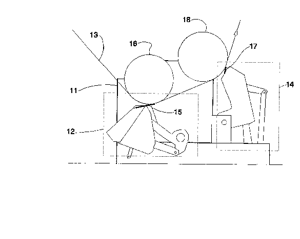
A method and apparatus for coating a
paper web (13). According to the method,
a coating mix is applied on a paper web
(13) using an applicator unit (12) which
forms a linear mechanical force on the
web (13) against a backing surface (16)
situated on the back side of the web
(13), and the coating mix applied on the
web (13) is doctored using a doctor unit
(14) acting against a backing surface
(18). According to the invention, the
application of the coating mix takes
place backed by a first backing surface
(16), and the coating mix is doctored
backed by a second backing surface (18),
whereby speed of at least one of said
backing surfaces (16, 18) is
independently controlled relative to the
speed of said first backing surface (16)
and the web speed in order to attain a
control the tensile stress of the web.
(Fig. 4)

Revendications

Note : Les revendications sont présentées dans la langue officielle dans laquelle elles ont été soumises.


Claims:
1. A method for coating a paper web (13), in which
method
- a coating mix is applied on the paper web
(13) using an applicator unit (12) which forms
a linear fixing point of the web (13) against a
backing surface (16) situated on the back side
of the web (13), and
- the coating mix applied on the web (13) is
doctored using a doctor unit (14) acting
against a backing surface (18),
c h a r a c t e r i z e d in that
- the application of the coating mix takes
place backed by a first backing surface (16),
and
- the coating mix is doctored backed by a
second backing surface (18), whereby
- speed of at least one of said backing
surfaces (16, 18) is independently controlled
relative to the speed of said first backing
surface (16) and/or the web speed in order to
attain a control the tensile stress of the web.
2. A method as defined in claim 1, c h a r a c t e r -
i z e d in that a roll (18) is used as the second
backing surface.
3. A method as defined in claim 1, c h a r a c t e r -
i z e d in that a backing belt (22) is used as the
second backing surface.

4. A method as defined in claim 1, c h a r a c t e r -
i z e d in that a backing roll (16) is used as the first
backing surface.
5. A method as defined in claim 1, c h a r a c t e r -
i z e d in that a backing surface operated with the help
of an air cushion is used as the first backing surface.
6. A method as defined in claim 1, c h a r a c t e r -
i z e d in that a backing belt is used as the first
backing surface.
7. An apparatus for coating a paper web (13), said
apparatus comprising
- an applicator unit (12),
- a backing surface (16) placed backing said
applicator unit (12),
- a doctor unit (14), and
- a backing surface (18) acting against said
doctor unit (14),
c h a r a c t e r i z e d in that
- said backing surface (18) of said doctor unit
(14) is separate from said backing surface (16)
of said applicator unit (12), whereby the speed
of said backing surface (18) of said doctor
unit (14) is independently adjustable relative
to the web speed and the tangential speed of
said backing surface (16) of said applicator
unit (12).

8. An apparatus as defined in claim 7, c h a r a c -
t e r i z e d in that both backing surfaces (16, 18)
have independent drive means.
9. An apparatus as defined in claim 7, c h a r a c -
t e r i z e d in that at least one of the backing
surfaces is a backing belt (22).
10. An apparatus as defined in claim 7, c h a r a c -
t e r i z e d in that one of the backing surfaces is a
backing surface operated with the help of an air cushion.

Description

Note : Les descriptions sont présentées dans la langue officielle dans laquelle elles ont été soumises.

2~?.~0
Method and apparatus for coating a paper web
The present invention relates to a method according to
the preamble of claim 1 for coating a paper web.
The invention also concerns an apparatus for coating a
paper web.
... : -.
According to prior-art techniques, a coating mix layer is
first metered onto a paper web using an applicator
apparatus and the coat is next smoothed with the help of
a doctor blade working against the backing roll of the
coater station.
Particularly in coater stations equipped with a nozzle
applicator, certain operating conditions have invoked
runnability problems of the web to be coated owing to the
fact that the applicator apparatus and the actual doctor
blade form two linear fixing points o~ the web onto a
single backing roll. Air conveyed along with the surface
texture of the paper web remains pocketed between the web
and the backing roll in the area delimited by said two
web fixing points. Then, an irregularly shaped air pouch
called blowing can develop in the area between the web
fixing points owing to such cause~ as, for instance, an
uneven distribution of web tension. The forces exerting
either a web braking and pulling effect at the web fixing
points behave so as to allow web slackening in the area
between the web fixing points. Furthermore, the web
moisture content increases in the application of the
coating mix, whereby the web tends to swell between the
web fixing points. This phenomenon causes a~ditional
slackening of the web.
Given an uneven tensile, thic~ness, porosity or other
profile across the web, web slackening oc~urs irregularly
across the web within the area between the web fixing
: . . ~ . .
- . . , . ~ . . ~

2 ~
points. This may cause curling in the machine direction,
which in turn may result in creasing.
It is an object of the present invention to overcome the
drawbacks of the above-described techniques and to
achieve an entirely novel method and appiaratus for
coating a paper web.
The invention is based on arranging the application step
and the actual doctoring step so that either step is
performed against a separate backing surface. Of these
backing surfaces, at least the latter either pulls the
web forward or at least moves substantially at equal
speed with the web.
More specifically, the method according to the invention
is characterized by what is stated in the characterizing
part of claim l.
Furthermore, the apparatus according to the invention is
characterized by what is stated in the characterizing
part of claim 7.
The invention provides significant benefits.
Owing to the separate backing surfaces, an improved
control of w~b tension between the web fixing points is
attained and the above-mentioned deleterious blowing or
slackening of the web between the fixing polnts can be
prevented.
In the following the invention is described in great~r
detail with the help of exemplifying embodiments
illustrated in the annexed drawings in which
Figure 1 shows diagrammatically the forces t~pically
involved in a prior-art embodiment.

2 ~
Figure 2 shows in a diagrammatic side view the blowing
effect caused by the forces illustrated in Fig. 1.
Figure 3a shows in a diagrammatic front view a stable
bloving effect caused by the forces illustrated in
Fig. 1.
Figure 3b shows in a diagrammatic front view an unstable
blowing effect caused by the forces illustrated in
Fig. 1.
Figure 4 shows a side view of an emhodiment of the
apparatus according to the invention.
Figure 5 shows a side view of an alternative embodiment
of the apparatus according to the invention.
The arrangement according to the invention achieves its
greatest benefits in conjunction with coaters forming a
web fixing point, e.g., nozzle coaters equipped with
metering/smoothing blades, while the invention is also
suited for use with roll coaters.
With reference to Fig. 1, the tensile stress T0 of a web
3 between the blades is expressed by the formula
T0 = T1 + T2 + F2 + F3 - F1 - F4, where
T1 is the tensile stress imposed in the web 3 by the
preceding rolls,
T2 is the tensile stress imposed in the web 3 by the
rolls subsequent to the nip,
FZ is the ~orce imposed in the web 3 by the metering/
smoothing blade 5,
F3 is the force imposed in the web 3 by the roll 1 in the
nip between the roll 1 and the metering/smoothing blade
5,
.

Fl is the force imposed in the web 3 by the roll l in the
nip between the roll l and the doctor blade 7, and
F4 is the force imposed in the web 3 by the doctor blade
7.
In this context, the force variables Fl - F4 must be
understood as the imposed total force divided by the web
cross section.
With reference to Fig. 2, two web fixing points cause an
air pouch 9, which at its worst can result in web
creasing when reaching the nip between the roll l and the
doctor blade.
Fig. 3a shows a stable situation in which an air pouch 9
has developed in front of the upper blade 7 owing to
excessive tensile stress T0. As the height of the air
pouch 9 in this case is constant across the web, the
situation is stable.
Fig. 3b in contrast illustrates an unstable running
situation in which the height of the air pouch 9 varies
across the web 3.
2~ With reference to Fig. 4, the web runnability problems
are solved according to the invention by placing the
applicator 12 against the first backing roll 16 and the
doctoring unit 14 against a second backing roll 18. In
this manner, the tensile stress of a web 13 between the
first linear web fixing point formed at the metering/
smoothing blade 15 and the second linear web fixing point
formed at the doctor blade 17 can be controlled by virtue
of, e.g., controlling the rotational speed of the second
backing roll 18. However, the tensile stress of the web
13 can also be implemented throllgh a speed control of the
first backing roll 16. Typically, the tangential speed of

21~?,~
the backing roll 18 is essentially equal to or higher
than the speed of the web 13.
With reference to Fig. 5, the doctor blade applicator can
be replaced by a roll applicator. In the embodiment
illustrated herein, the roll 18 shown in Fig. 4 is
replaced by a smaller-diameter roll 20 on which a backing
belt 22 with adjustable speed runs.
In both above-described embodiments the tangential speed
of the second backing surface 18 or 22, respectively, is
essentially equal to or higher than the speed of the web
13.
In principle, the backing roll 16 shown in Fig. 5 can
alternati~ely be replaced by a backing sur~ace which is
supported by air injected between said backing surface
and the web, whereby the web runs on an air cushion
against the roll applicator. Then, the tensile stress of
the web 13 is adjusted through the speed control of the
backing belt 22.
For reasons of spatial limitations in paper machines, the
rolls 16 and 18 preferably have a small diameter.
Therefore, a backing belt arrangement 22 such as shown in
Fig. 5 is according to the invention preferred for the
space savings it offers.
Further, the small dimensions of the backiny roll/belt
arrangements also provide a reasonable distance between
the metering/smoothing blade or roll and the doctor blade
as required by the coating technique employed.
Obviously, the backing belt arrangement 20, 22 shown in
3~ ~ig. 5 can also be implemented to replace the first
backing roll 16. Further, even both backing rolls can be

2 ~
6 :
replaced by backing belts, re~pectively, in the same
embodiment.

Dessin représentatif
Une figure unique qui représente un dessin illustrant l'invention.
États administratifs

2024-08-01 : Dans le cadre de la transition vers les Brevets de nouvelle génération (BNG), la base de données sur les brevets canadiens (BDBC) contient désormais un Historique d'événement plus détaillé, qui reproduit le Journal des événements de notre nouvelle solution interne.

Veuillez noter que les événements débutant par « Inactive : » se réfèrent à des événements qui ne sont plus utilisés dans notre nouvelle solution interne.

Pour une meilleure compréhension de l'état de la demande ou brevet qui figure sur cette page, la rubrique Mise en garde , et les descriptions de Brevet , Historique d'événement , Taxes périodiques et Historique des paiements devraient être consultées.

Historique d'événement

Description Date
Le délai pour l'annulation est expiré 1996-05-04
Demande non rétablie avant l'échéance 1996-05-04
Réputée abandonnée - omission de répondre à un avis sur les taxes pour le maintien en état 1995-11-06
Inactive : Demande ad hoc documentée 1995-11-06
Demande publiée (accessible au public) 1994-05-14

Historique d'abandonnement

Date d'abandonnement Raison Date de rétablissement
1995-11-06
Titulaires au dossier

Les titulaires actuels et antérieures au dossier sont affichés en ordre alphabétique.

Titulaires actuels au dossier
VALMET PAPER MACHINERY INC.
Titulaires antérieures au dossier
JUKKA KOSKINEN
VILHO NISSINEN
Les propriétaires antérieurs qui ne figurent pas dans la liste des « Propriétaires au dossier » apparaîtront dans d'autres documents au dossier.
Documents

Pour visionner les fichiers sélectionnés, entrer le code reCAPTCHA :


Pour visualiser une image, cliquer sur un lien dans la colonne description du document. Pour télécharger l'image (les images), cliquer l'une ou plusieurs cases à cocher dans la première colonne et ensuite cliquer sur le bouton "Télécharger sélection en format PDF (archive Zip)" ou le bouton "Télécharger sélection (en un fichier PDF fusionné)".

Liste des documents de brevet publiés et non publiés sur la BDBC .

Si vous avez des difficultés à accéder au contenu, veuillez communiquer avec le Centre de services à la clientèle au 1-866-997-1936, ou envoyer un courriel au Centre de service à la clientèle de l'OPIC.


Description du
Document 
Date
(aaaa-mm-jj) 
Nombre de pages   Taille de l'image (Ko) 
Revendications 1994-05-13 3 86
Abrégé 1994-05-13 1 26
Dessins 1994-05-13 5 236
Description 1994-05-13 6 233
Dessin représentatif 1998-07-29 1 11