Sélection de la langue

Search

Sommaire du brevet 2106436 

Énoncé de désistement de responsabilité concernant l'information provenant de tiers

Une partie des informations de ce site Web a été fournie par des sources externes. Le gouvernement du Canada n'assume aucune responsabilité concernant la précision, l'actualité ou la fiabilité des informations fournies par les sources externes. Les utilisateurs qui désirent employer cette information devraient consulter directement la source des informations. Le contenu fourni par les sources externes n'est pas assujetti aux exigences sur les langues officielles, la protection des renseignements personnels et l'accessibilité.

Disponibilité de l'Abrégé et des Revendications

L'apparition de différences dans le texte et l'image des Revendications et de l'Abrégé dépend du moment auquel le document est publié. Les textes des Revendications et de l'Abrégé sont affichés :

  • lorsque la demande peut être examinée par le public;
  • lorsque le brevet est émis (délivrance).
(12) Brevet: (11) CA 2106436
(54) Titre français: TRANSMISSION A CABLE POUR CAGE D'ASCENCEUR, A RAPPORT QUATRE POUR UN
(54) Titre anglais: FOUR TO ONE TRANSMISSION RATIO ROPE ARRANGEMENT FOR AN ELEVATOR CAR
Statut: Durée expirée - au-delà du délai suivant l'octroi
Données bibliographiques
(51) Classification internationale des brevets (CIB):
  • B66B 07/06 (2006.01)
  • B66B 11/08 (2006.01)
(72) Inventeurs :
  • DE JONG, JOHANNES (Finlande)
(73) Titulaires :
  • KONE CORPORATION
(71) Demandeurs :
  • KONE CORPORATION (Finlande)
(74) Agent: G. RONALD BELL & ASSOCIATES
(74) Co-agent:
(45) Délivré: 1997-05-06
(22) Date de dépôt: 1993-09-17
(41) Mise à la disponibilité du public: 1994-03-19
Requête d'examen: 1994-05-26
Licence disponible: S.O.
Cédé au domaine public: S.O.
(25) Langue des documents déposés: Anglais

Traité de coopération en matière de brevets (PCT): Non

(30) Données de priorité de la demande:
Numéro de la demande Pays / territoire Date
FI 924207 (Finlande) 1992-09-18

Abrégés

Abrégé français

Une transmission à câble pour un ascenseur possède au moins deux paires de poulies de support montées sous la cage d'ascenseur, et au moins deux poulies de dérivation montées sur une paroi de la cage d'ascenseur. Les câbles de levage passent sous les poulies de support pour supporter la cage d'ascenseur, et sur les poulies de dérivation de telle manière que le rapport de transmission entre la vitesse de l'ascenseur et la vitesse de rotation de l'appareil de levage soit au moins 1:4.


Abrégé anglais

A rope arrangement for an elevator has at least two pairs of support pulleys mounted under the elevator car, and at least two diverter pulleys mounted on a wall of the elevator shaft. The hoisting ropes run under the support pulleys to support the elevator car, and over the diverter pulleys in such a manner that the transmission ratio between the speed of the elevator car and the rotational speed of the hoisting machine is at least 1:4.

Revendications

Note : Les revendications sont présentées dans la langue officielle dans laquelle elles ont été soumises.


THE EMBODIMENTS OF THE INVENTION IN WHICH AN EXCLUSIVE
PROPERTY OR PRIVILEGE IS CLAIMED ARE DEFINED AS FOLLOWS:
1. A hoist rope arrangement for an elevator
comprising a hoisting machine and an elevator car supported
within an elevator shaft by a hoisting rope which engages at
least two pairs of supporting pulleys operatively disposed on
the under-side of said elevator car, and at least two diverter
pulleys located in said elevator shaft at a level higher than
that which can be reached by said supporting pulleys, wherein
said hoisting rope engages, in sequence, a first pair of said
support pulleys, one of said diverter pulleys and a second
pair of said support pulleys as it runs between an anchor
point and the hoisting machine, whereby the transmission ratio
between the speed of the elevator car and the rotational speed
of the hoisting machine is at least 1:4.
2. A hoist rope arrangement for an elevator
comprising a hoisting machine and an elevator car supported
within an elevator shaft by a hoisting rope, comprising:
at least two pairs of supporting pulleys operatively
disposed on the under-side of said elevator car, respective
ones of each of said pairs being cooperatively disposed
adjacent opposite sides of said elevator car;
at least two diverter pulleys, each of said diverter
pulleys being disposed on a wall of said elevator shaft at a
level which is higher than that which can be reached by said
supporting pulleys;
said hoisting rope being arranged to run from the
hoisting machine, over a first one of said diverter pulleys,
then pass under said elevator car via a first pair of
supporting pulleys, then pass over a second one of said
diverter pulleys, the rope then passing back under said
elevator car via a second pair of supporting pulleys and
terminating at an anchor point located at a level which is
equal to or higher than that of said diverter pulleys, whereby
the transmission ratio between the speed of the elevator car

and the rotational speed of the hoisting machine is at least
1:4.
3. An elevator rope arrangement according to claim
2, wherein the plane of rotation of at least one of said
diverter pulleys is oriented at an angle in the range of 25° -
155° with respect to the plane of rotation of said support
pulleys.
4. An elevator rope arrangement according to claim
1, 2 or 3, wherein the number of support pulleys is four, said
support pulleys being disposed in a substantially rectangular
arrangement.
5. An elevator rope arrangement according to claim
1, 2 or 3, wherein said support pulleys are disposed
substantially symmetrically about an axis of symmetry of said
elevator car.
6. An elevator including a hoisting rope and
elevator car comprising:
a hoisting machine and a hoisting rope for moving
the elevator car;
four support pulleys located below the elevator car;
three diverting pulleys mounted on a shaft for the
elevator car;
the hoisting rope running in sequence from a
traction sheave of an hoisting motor to a first diverting
pulley of the hoisting motor to a second diverting pulley
mounted on the shaft to a first and second support pulley
located below the elevator car to a third diverting pulley
mounted on the shaft to a third and fourth pulley located
below the elevator car to a rope anchorage located on the
shaft to which the rope is attached;
so that the transmission ratio between the speed of
the elevator car and the rotational speed of the hoisting
machine is at least 1:4.

7. An elevator including a hoisting rope and
elevator car according to claim 6, wherein said diverting
pulleys mounted on the shaft are placed above the elevator
car.
8. An elevator including a hoisting rope and
elevator car according to claim 6, wherein the number of
support pulleys is four, and the support pulleys are arranged
below the elevator car at an angle relative to a line going
through two diverting pulleys mounted on the same wall of the
shaft so that the line going through the diverting pulleys and
the center line of the support pulleys below the elevator car
form an angle which varies in the range 25°-155°.
9. An elevator including a hoisting rope and
elevator car according to claim 6, wherein the number of
support pulleys is four, and the support pulleys are arranged
below the elevator car and located substantially at the points
of a rectangle.
10. An elevator including a hoisting rope and
elevator car according to claim 6, wherein said diverting
pulleys mounted on the shaft are located above the support
pulleys below the elevator car.
11. An elevator including a hoisting rope and
elevator car according to claim 6, wherein there is a
counterweight to which the hoisting rope is attached.

Description

Note : Les descriptions sont présentées dans la langue officielle dans laquelle elles ont été soumises.

21~643~
The present invention relates to an elevator rope
arrangement, and in particular to a rope arrangement for
elevators designed to carry heavy loads.
At present, elevators are used in which the elevator
car is supported by a hoisting rope which runs via a pair of
pulleys mounted under the elevator car. Such solutions can
be used especially when the hoisting machine of the elevator
is located at the side of the elevator shaft. In conventional
elevator systems having rope pulleys mounted under the
elevator car, the transmission ratio is 1:2. In this context,
transmission ratio refers to the speed of the elevator car in
relation to the rope speed.
In large and heavy elevator applications (i.e. when
the elevator car and hoisting machine must carry heavy loads),
hydraulic elevators are typically used. These often have a
multistage lifting cylinder, particularly in cases where high
load capacity and a large lifting height are required.
However, such lifting cylinders are very expensive and their
maintenance is also expensive and complicated. Because of the
risk of buckling, the cylinders also tend to have a relatively
low lifting height limit.
An object of the present invention is to overcome
the drawbacks of prior art techniques and to achieve a rope-
supported elevator system having a high load capacity.
According to an aspect of the present invention
there is provided a hoist rope arrangement for an elevator
comprising a hoisting machine and an elevator car supported
within an elevator shaft by a hoisting rope which engages at
least two pairs of supporting pulleys operatively disposed on
the under-side of said elevator car, and at least two diverter
pulleys located in said elevator shaft at a level higher than
that which can be reached by said supporting pulleys, wherein
said hoisting rope engages, in sequence, a first pair of said
support pulleys, one of said diverter pulleys and a second
pair of said support pulleys as it runs between an anchor
point and the hoisting machine, whereby the transmission ratio
*

2106~36
between the speed of the elevator car and the rotational speed
of the hoisting machine is at least 1:4.
According to another aspect of the present
invention, there is provided a hoist rope arrangement for an
elevator comprising a hoisting machine and an elevator car
supported within an elevator shaft by a hoisting rope,
comprising: at least two pairs of supporting pulleys
operatively disposed on the under-side of said elevator car,
respective ones of each of said pairs being cooperatively
disposed adjacent opposite sides of said elevator car; at
least two diverter pulleys, each of said diverter pulleys
being disposed on a wall of said elevator shaft at a level
which is higher than that which can be reached by said
supporting pulleys; said hoisting rope being arranged to run
from the hoisting machine, over a first one of said diverter
pulleys, then pass under said elevator car via a first pair
of supporting pulleys, then pass over a second one of said
diverter pulleys, the rope then passing back under said
elevator car via a second pair of supporting pulleys and
terminating at an anchor point located at a level which is
equal to or higher than that of said diverter pulleys, whereby
the transmission ratio between the speed of the elevator car
and the rotational speed of the hoisting machine is at least
1:4.
The rope arrangement according to the present
invention provides several advantages, particularly for high
load capacity elevators. In particular, it enables small
geared elevator machines to be used instead of large (and more
expensive) gearless machines which are required in
conventional elevators having a transmission ratio of 1:2.
Moreover, when the rope arrangement of the invention is used,
the elevator car can be supported in a completely stable and
balanced manner, so that forces imposed on the guide rails of
the elevator are significantly reduced. Furthermore, tensile
forces in the rope is only 1~ or less of the total weight of

210643~
the car, thereby allowing lighter ropes to be used without
sacrificing safety or the load capacity of the elevator.
The rope arrangement of the present invention
permits the installation of an elevator system having the same
load carrying capacity as a hydraulic elevator, but which is,
considerably lighter and cheaper. Furthermore, a high load
capacity elevator using the rope arrangement of the present
invention is capable of having a substantially greater
lighting height than is practical with a hydraulic system.
In the following, the invention is described in
detail by the aid of an example by referring to the attached
drawings, in which:
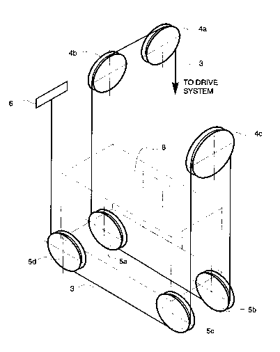
Figure 1 is a schematic illustration of a rope
arrangement according to the present invention;
Figure 2 is a schematic illustration of a rope
arrangement for the elevator machine; and
Figure 3 is a diagrammatic top view a rope elevator
employing a rope arrangement according to the present
invention.
Note that throughout the figures, like features are
identified by like reference numerals.
Referring to Figure 1, in the rope arrangement of
the invention, the hoisting ropes 3 are passed via four
pulleys 5a - 5d mounted under the elevator car at the points
of a rectangle. In addition, the ropes pass round three
diverting pulleys 4a - 4c mounted on the wall of the elevator
shaft above the elevator car. By using an arrangement where
the ropes run via four pulleys under the elevator car as
illustrated by Figure 1, a transmission ratio of 1:4 between
the car speed and the speed of rotation of the traction sheave
will be achieved.
The ropes 3 run from the traction sheave 1 of the
hoisting motor (Figure 2) to one 2a of the two diverting
pulleys of the machine and further to the first overhead
diverting pulley 4a mounted on the wall of the elevator shaft.
From here, the ropes 3 go to the second overhead diverting
B

210643~
pulley 4b and further to the first support pulley 5a mounted
under the elevator car. Next, the ropes 3 pass via the second
support pulley 5b, which is aligned with the first one in the
running direction of the rope, to the third overhead diverting
pulley 4c. From this pulley they run via the third and fourth
support pulleys 5c and 5d to a rope anchorage 6 in the wall.
The other rope branch goes from the traction sheave
1 (Figure 2) via the other diverting pulley 2b to the
counterweight. The counterweight rope arrangement can be
implemented independently of the car rope arrangement, so it
will not be described here in detail.
Figure 3 illustrates an elevator car 8 which has
support pulleys 5a - 5d mounted under it as described above
and moves along guide rails 9 in an elevator shaft 7. Mounted
on the wall of the elevator shaft are overhead diverting
pulleys 4a - 4c. The elevator machine consists of a hoisting
motor 10 placed at the side of the shaft 7, a gear 11, a
traction sheave 1 and a diverting pulley 2a of the hoisting
motor. Figure 3 also shows the counterweight 12.
The support pulleys 5a - 5d are arranged under the
elevator car 8 so that the plane of rotation thereof is
oriented at an angle with respect to the plane of rotation of
the diverting pulleys 4a and 4b (indicated by the dashed line
through pulleys 4a and 4b in Figure 3). This angle can be
between 25 and 155. In the embodiment illustrated in Figure
3, the angle is 90.
It will be obvious to a person skilled in the art
that different embodiments of the invention are not restricted
to the example described above, but that they may instead be
varied within the scope of the following claims.
It will also be noted that throughout the drawings
and the above description, a single hoisting rope of the
elevator system is illustrated and discussed. It will be
readily apparent, however, that the rope arrangement of the
present invention will work equally well with two or more

21 0643~
parallel hoist ropes instead of
illustrated. a slngle hoist rope as
B

Dessin représentatif
Une figure unique qui représente un dessin illustrant l'invention.
États administratifs

2024-08-01 : Dans le cadre de la transition vers les Brevets de nouvelle génération (BNG), la base de données sur les brevets canadiens (BDBC) contient désormais un Historique d'événement plus détaillé, qui reproduit le Journal des événements de notre nouvelle solution interne.

Veuillez noter que les événements débutant par « Inactive : » se réfèrent à des événements qui ne sont plus utilisés dans notre nouvelle solution interne.

Pour une meilleure compréhension de l'état de la demande ou brevet qui figure sur cette page, la rubrique Mise en garde , et les descriptions de Brevet , Historique d'événement , Taxes périodiques et Historique des paiements devraient être consultées.

Historique d'événement

Description Date
Inactive : Périmé (brevet - nouvelle loi) 2013-09-17
Inactive : CIB de MCD 2006-03-11
Lettre envoyée 2003-04-01
Lettre envoyée 1998-08-26
Lettre envoyée 1997-09-22
Accordé par délivrance 1997-05-06
Exigences pour une requête d'examen - jugée conforme 1994-05-26
Toutes les exigences pour l'examen - jugée conforme 1994-05-26
Demande publiée (accessible au public) 1994-03-19

Historique d'abandonnement

Il n'y a pas d'historique d'abandonnement

Historique des taxes

Type de taxes Anniversaire Échéance Date payée
TM (brevet, 5e anniv.) - générale 1998-09-17 1997-08-15
TM (brevet, 6e anniv.) - générale 1999-09-17 1998-08-12
TM (brevet, 7e anniv.) - générale 2000-09-18 2000-08-09
TM (brevet, 8e anniv.) - générale 2001-09-17 2001-08-15
TM (brevet, 9e anniv.) - générale 2002-09-17 2002-08-14
Enregistrement d'un document 2003-02-28
TM (brevet, 10e anniv.) - générale 2003-09-17 2003-08-13
TM (brevet, 11e anniv.) - générale 2004-09-17 2004-08-16
TM (brevet, 12e anniv.) - générale 2005-09-19 2005-08-17
TM (brevet, 13e anniv.) - générale 2006-09-18 2006-08-17
TM (brevet, 14e anniv.) - générale 2007-09-17 2007-08-15
TM (brevet, 15e anniv.) - générale 2008-09-17 2008-08-13
TM (brevet, 16e anniv.) - générale 2009-09-17 2009-09-04
TM (brevet, 17e anniv.) - générale 2010-09-17 2010-09-02
TM (brevet, 18e anniv.) - générale 2011-09-19 2011-09-02
TM (brevet, 19e anniv.) - générale 2012-09-17 2012-09-07
Titulaires au dossier

Les titulaires actuels et antérieures au dossier sont affichés en ordre alphabétique.

Titulaires actuels au dossier
KONE CORPORATION
Titulaires antérieures au dossier
JOHANNES DE JONG
Les propriétaires antérieurs qui ne figurent pas dans la liste des « Propriétaires au dossier » apparaîtront dans d'autres documents au dossier.
Documents

Pour visionner les fichiers sélectionnés, entrer le code reCAPTCHA :


Pour visualiser une image, cliquer sur un lien dans la colonne description du document. Pour télécharger l'image (les images), cliquer l'une ou plusieurs cases à cocher dans la première colonne et ensuite cliquer sur le bouton "Télécharger sélection en format PDF (archive Zip)" ou le bouton "Télécharger sélection (en un fichier PDF fusionné)".

Liste des documents de brevet publiés et non publiés sur la BDBC .

Si vous avez des difficultés à accéder au contenu, veuillez communiquer avec le Centre de services à la clientèle au 1-866-997-1936, ou envoyer un courriel au Centre de service à la clientèle de l'OPIC.


Description du
Document 
Date
(aaaa-mm-jj) 
Nombre de pages   Taille de l'image (Ko) 
Abrégé 1997-03-23 1 13
Description 1997-03-23 5 204
Revendications 1997-03-23 3 120
Dessins 1997-03-23 2 39
Revendications 1994-05-24 2 86
Abrégé 1994-05-24 1 35
Description 1994-05-24 4 241
Dessins 1994-05-24 2 79
Dessin représentatif 1998-08-20 1 12
Correspondance 1997-09-21 1 11
Taxes 1998-06-03 1 48
Correspondance 1998-08-25 1 12
Taxes 1997-05-22 1 54
Taxes 1996-09-08 1 63
Taxes 1995-09-14 1 41
Correspondance de la poursuite 1994-05-25 1 47
Correspondance reliée au PCT 1997-02-18 1 28
Correspondance de la poursuite 1996-06-02 4 106
Correspondance de la poursuite 1994-07-04 5 228
Courtoisie - Lettre du bureau 1994-06-27 1 40
Demande de l'examinateur 1996-03-07 2 72