Sélection de la langue

Search

Sommaire du brevet 2112147 

Énoncé de désistement de responsabilité concernant l'information provenant de tiers

Une partie des informations de ce site Web a été fournie par des sources externes. Le gouvernement du Canada n'assume aucune responsabilité concernant la précision, l'actualité ou la fiabilité des informations fournies par les sources externes. Les utilisateurs qui désirent employer cette information devraient consulter directement la source des informations. Le contenu fourni par les sources externes n'est pas assujetti aux exigences sur les langues officielles, la protection des renseignements personnels et l'accessibilité.

Disponibilité de l'Abrégé et des Revendications

L'apparition de différences dans le texte et l'image des Revendications et de l'Abrégé dépend du moment auquel le document est publié. Les textes des Revendications et de l'Abrégé sont affichés :

  • lorsque la demande peut être examinée par le public;
  • lorsque le brevet est émis (délivrance).
(12) Brevet: (11) CA 2112147
(54) Titre français: DISPOSITIF D'ARRET POUR MARTEAU D'EAU SILENCIEUX
(54) Titre anglais: PING-FREE WATER HAMMER ARRESTER
Statut: Périmé et au-delà du délai pour l’annulation
Données bibliographiques
(51) Classification internationale des brevets (CIB):
  • F16L 55/045 (2006.01)
(72) Inventeurs :
  • PERROT, CHARLES H. (Etats-Unis d'Amérique)
  • KOUICHI, SUZUKI (Japon)
(73) Titulaires :
  • PRECISION PLUMBING PRODUCTS, INC.
  • VENN CO. LTD.
(71) Demandeurs :
  • PRECISION PLUMBING PRODUCTS, INC. (Etats-Unis d'Amérique)
  • VENN CO. LTD. (Japon)
(74) Agent: GOWLING WLG (CANADA) LLP
(74) Co-agent:
(45) Délivré: 1998-02-17
(22) Date de dépôt: 1993-12-22
(41) Mise à la disponibilité du public: 1995-06-23
Requête d'examen: 1994-04-13
Licence disponible: S.O.
Cédé au domaine public: S.O.
(25) Langue des documents déposés: Anglais

Traité de coopération en matière de brevets (PCT): Non

(30) Données de priorité de la demande: S.O.

Abrégés

Abrégé français

Cette invention concerne un anti-coup de bélier formé d'un corps cylindrique à l'intérieur duquel est logé un piston à mouvement alternatif et un raccord pour son raccordement à une tuyauterie d'eau sous pression. Une butée/pare-choc est interposé entre le piston et le raccord pour prévenir le bruit qui se produirait si ces deux éléments s'entrechoquaient pendant le va-et-vient du piston.


Abrégé anglais


A water hammer arrester comprises a cylindrical body
housing a piston for free sliding reciprocal movement and a
connector for connection to a water conduit system which
carries water under pressure. An abutment-bumper combination
is interposed between piston and connector to avoid the ping
which would be produced is these two elements of the assembly
were to collide during reciprocation of the piston.

Revendications

Note : Les revendications sont présentées dans la langue officielle dans laquelle elles ont été soumises.


The embodiments of the invention in which an
exclusive property or privilege is claimed are defined
as follows:
1. A ping-free water hammer arrester comprising:
a) a hollow cylindrical body closed at one
end and open at the other,
b) a piston freely slidable within the body
and forming in the closed end thereof a hermetically
sealed gas chamber,
c) a hollow, cylindrical connector open at
both ends and secured to the open end of the body for
connection to a conduit conveying fluid under pressure,
thereby placing the body in open communication with the
conduit, and the fluid in the conduit in pressure
contact with the piston, whereby to reciprocate the
piston with fluctuations in fluid pressure between a
retracted position and an advanced position,
d) an abutment on the connector positioned
opposite the piston and in its path of travel,
e) resilient shock-absorbing bumper means,
and
f) bumper means mounting means positioning
the bumper means between the piston and the abutment
for impact by the piston,
g) the bumper means mounting means being
positioned on the end of the piston facing the
abutment.
2. A ping-free water hammer arrester comprising:
a) a hollow cylindrical body closed at one
end and open at the other,
b) a piston freely slidable within the body
and forming in the closed end thereof a hermetically
sealed gas chamber,

c) a hollow, cylindrical connector open at
both ends and secured to the open of the body for
connection to a conduit conveying fluid under pressure,
thereby placing the body in open communication with the
conduit, and the fluid in the conduit in pressure
contact with the piston, whereby to reciprocate the
piston with fluctuations in fluid pressure between a
retracted position and an advanced position,
d) an abutment on the connector positioned
opposite the piston and in its path of travel,
e) resilient shock-absorbing bumper means,
and
f) bumper means mounting means positioning
the bumper means between the piston and the abutment
for impact by the piston,
g) the bumper means comprising a resilient
O-ring and O-ring mounting means mounting the O-ring on
the piston.
3. The water hammer arrester of claim 2 wherein
the O-ring mounting means comprises adhesive means.

Description

Note : Les descriptions sont présentées dans la langue officielle dans laquelle elles ont été soumises.

~ Z112~7
PING-FREE WATER HAMMER ARRESTER
BACKGROUND OF THE INVENTION
1. Field of the Invention
This invention relates to water hammer arresters; i.e. to
devices for preventing the development of water hammer in
conduits conveying water under pressure and under conditions
of interrupted flow.
2. Description of the Prior Art
The familiar phenomenom of water hammer is caused by the
development of hydraulic shock waves generated by the sudden
stopping of fluid flow within the confines of a conduit system
carrying water under pressure. This condition results from
the rapid closing of positive valves incorporated within the
system. In addition to the production of unpleasant noise
effects, fluid hammer if allowed to persist for any length of
time, will result in broken conduits and damage to other
components of the conduit system.
Various types of fluid hammer arresters are known to the
prior art. The most commonly employed of such devices
includes expandable bellows or diaphragms which absorb the
shock. These are so subject to failure that their service
life is short.
Another type of fluid hammer arrester involves the

" ' ~ 21121~7
application of a piston working against the pressure developed
by a compressed gas chamber. Such a device is disclosed in
Perrott et al, U.S. Patent No. 3,633,627. Although widely and
successfully used, water hammer arresters of the Perrott et al
class are characterized in use by a noise generating problem.
When subjected to rapid and substantial pressure drop, the
metallic piston with which they are provided occasionally
forcibly contacts an opposed metallic wall. This causes the
production of an unpleasant metallic sound, or "ping". The
arresters accordingly defeat their own purpose in that they
themselves become a sound-producing instrument.
It is the general purpose of the present invention to
provide a water hammer arrester which overcomes this problem,
and which is ping-free.
THE PRESENT INVENTION
In accordance with the present invention, a ping-free
water hammer arrester is provided which comprises a hollow
cylindrical body closed at one end and open at the other. A
piston is freely slidable within the body and forms in the
closed end thereof a hermatically sealed gas chamber.
A hollow, cylindrical connector ("nipple"), open at both
ends, is secured to the open end of the body for connection to
a conduit conveying fluid under pressure. This places the
body in open communication with the conduit, and the fluid in
the conduit in pressure contact with the piston.
-

~ 21121~7
Reciprocation of the piston with fluctuation in fluid pressure
between advanced and retracted positions accordingly occurs.
An abutment is provided on the connector. It is
positioned opposite the piston and in its path of travel.
A shock absorbing bumper is mounted on mounting means
which positions it between the piston and the abutment. The
bumper is of resilient material and absorbs the shock of the
piston if it should slam into the abutment. The noise problem
accordingly is eliminated.
THE DRAWINGS
In the drawings:
Fig. 1 is a fragmentary view in side elevation of a
piping system including the herein described water hammer
arrester.
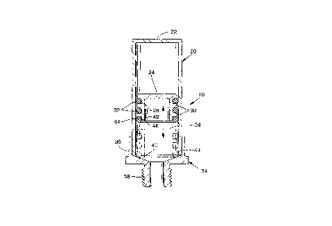
Fig. 2 is a longitudinal sectional view of the arrester
in its assembled condition.
Fig. 3 is an exploded top perspective view of the
arrester.
DESCRIPTION OF A PREFERRED EMBODIMENT OF THE INVENTION
The presently described water hammer arrester is
indicated generally at 10, Fig. 1. It is adaptable for
installation in fluid conveying systems wherever there is a
likelihood of the development of fluid hammer. Such a
situation is present in the illustrated example where there is
fluid flow through a conduit system 12 including a valve 14.

~ 2112147
As is well known, closing the valve suddenly and thusarresting the flow of fluid through the conduit system may
result in setting up water hammer conditions.
In general, the water hammer arrester should be placed as
near the source of shock as possible. It also should be
installed in such a manner that there is an unobstructed shock
path to the arrester.
Thus, in the illustration of Fig. 1, the arrester may be
included in the conduit system simply by inserting a T 16 to
which the arrester 10 is coupled.
The construction of the arrester and its manner of
operation are shown in detail in Figs. 2 and 3.
The arrester includes a hollow cylindrical body 20 which
is closed at one end 22. It may be made of brass or other
suitable metal.
A piston indicated generally at 24 is freely slidable
within the cylindrical body. Its peripheral surface is formed
with annular grooves 28 and intervening lands 30. Sealing
rings (O-rings) 32 seat in the grooves. They may be made of
natural or artificial rubber, plastic or other suitable
material.
A connector indicated generally at 34 by means of which
the arrester is coupled to the fluid conducting system is
mounted by soldering or other suitable method on the open end
Of cylinder 20.

~ 2112147
The connector has a cylindrical body or cap segment 36
which fits over the open end of cylindrical body 20 and in
sealed relation thereto, as by means of soldering. A threaded
attaching segment 38 facilitates its application to the piping
components of the system.
The foregoing arrangement places cylinder 20 in open
communication with the conduit components of the system. It
also places the fluid in the conduit in pressure contact with
the piston, whereby to reciprocate the piston with
fluctuations in water pressure between a retracted position in
which the piston is housed within the cylinder, and an
advanced position in which it can progress into contact with
connector 34. Since both of these components may be made of
metal, there may result the "ping" which it is the purpose of
this invention to prevent.
To this end, there is provided an abutment on connector
34. This is positioned opposite the piston and in its path of
travel. In the illustrated form of the invention, the
abutment comprises inwardly tapered (with reference to the
direction of travel of the piston) abutment surface 40. This
preferably is contoured in the geometry of a truncated cone,
as is evident from Fig. 2.
Shock-absorbing bumper means are positioned between
piston 24 and abutment surface 40. Although the bumper means
may be positioned on either one of these two components, it

~ 2112147
preferably is mounted on piston 24.
To this end the forward (with reference to the direction
of travel) margin of the piston is provided with an annular
marginal recess 42. This recess seats a resilient bumper
ring, such as O-ring 44. As in the case of O-rings 32, O-ring
44 may be fabricated from natural or synthetic rubber, or a
suitable resilient plastic.
Adhesive 46 is interposed between the bumper ring and the
recess in which it is seated to insure against displacement
during operation of the assembly.
OPERATION
In the operation of the herein described ping-free water
hammer arrester, the unit is inserted in the water conduit
system in the manner illustrated in Fig. 1. As fluctuations
in house line water pressure occur, piston 24 will reciprocate
inside cylinder 20. This absorbs the pressure shocks and
prevents water hammer.
In the event that metallic piston 24 should slam against
metallic connector 34 during operation of the device, the
collision is prevented and the shock absorbed, by virtue of
bumper ring 44 of the piston colliding with abutment surface
40 of the connector.
Both water hammer noise and arrester ping thus are
eliminated in a simple, integral device.
It is to be understood that the form of my invention

~ 2112147
herein shown and described is to be taken as a preferred
example of the same and that various changes in the shape,
size and arrangement of parts may be resorted to without
departing from the spirit of my invention or the scope of the
subjoined claims.
I claim:

Dessin représentatif
Une figure unique qui représente un dessin illustrant l'invention.
États administratifs

2024-08-01 : Dans le cadre de la transition vers les Brevets de nouvelle génération (BNG), la base de données sur les brevets canadiens (BDBC) contient désormais un Historique d'événement plus détaillé, qui reproduit le Journal des événements de notre nouvelle solution interne.

Veuillez noter que les événements débutant par « Inactive : » se réfèrent à des événements qui ne sont plus utilisés dans notre nouvelle solution interne.

Pour une meilleure compréhension de l'état de la demande ou brevet qui figure sur cette page, la rubrique Mise en garde , et les descriptions de Brevet , Historique d'événement , Taxes périodiques et Historique des paiements devraient être consultées.

Historique d'événement

Description Date
Le délai pour l'annulation est expiré 2006-12-22
Lettre envoyée 2005-12-22
Accordé par délivrance 1998-02-17
Préoctroi 1997-11-14
Inactive : Taxe finale reçue 1997-11-14
Un avis d'acceptation est envoyé 1997-09-02
Lettre envoyée 1997-09-02
Un avis d'acceptation est envoyé 1997-09-02
Inactive : Renseign. sur l'état - Complets dès date d'ent. journ. 1997-08-27
Inactive : Dem. traitée sur TS dès date d'ent. journal 1997-08-27
Inactive : CIB attribuée 1997-07-25
Inactive : CIB enlevée 1997-07-25
Inactive : CIB en 1re position 1997-07-25
Inactive : Approuvée aux fins d'acceptation (AFA) 1997-07-25
Demande publiée (accessible au public) 1995-06-23
Exigences pour une requête d'examen - jugée conforme 1994-04-13
Toutes les exigences pour l'examen - jugée conforme 1994-04-13

Historique d'abandonnement

Il n'y a pas d'historique d'abandonnement

Taxes périodiques

Le dernier paiement a été reçu le 1997-11-05

Avis : Si le paiement en totalité n'a pas été reçu au plus tard à la date indiquée, une taxe supplémentaire peut être imposée, soit une des taxes suivantes :

  • taxe de rétablissement ;
  • taxe pour paiement en souffrance ; ou
  • taxe additionnelle pour le renversement d'une péremption réputée.

Les taxes sur les brevets sont ajustées au 1er janvier de chaque année. Les montants ci-dessus sont les montants actuels s'ils sont reçus au plus tard le 31 décembre de l'année en cours.
Veuillez vous référer à la page web des taxes sur les brevets de l'OPIC pour voir tous les montants actuels des taxes.

Historique des taxes

Type de taxes Anniversaire Échéance Date payée
TM (demande, 4e anniv.) - générale 04 1997-12-22 1997-11-05
Taxe finale - générale 1997-11-14
TM (brevet, 5e anniv.) - générale 1998-12-22 1998-11-25
TM (brevet, 6e anniv.) - générale 1999-12-22 1999-10-14
TM (brevet, 7e anniv.) - générale 2000-12-22 2000-10-25
TM (brevet, 8e anniv.) - générale 2001-12-24 2001-10-22
TM (brevet, 9e anniv.) - générale 2002-12-23 2002-10-15
TM (brevet, 10e anniv.) - générale 2003-12-22 2003-10-15
TM (brevet, 11e anniv.) - générale 2004-12-22 2004-11-01
Titulaires au dossier

Les titulaires actuels et antérieures au dossier sont affichés en ordre alphabétique.

Titulaires actuels au dossier
PRECISION PLUMBING PRODUCTS, INC.
VENN CO. LTD.
Titulaires antérieures au dossier
CHARLES H. PERROT
SUZUKI KOUICHI
Les propriétaires antérieurs qui ne figurent pas dans la liste des « Propriétaires au dossier » apparaîtront dans d'autres documents au dossier.
Documents

Pour visionner les fichiers sélectionnés, entrer le code reCAPTCHA :


Pour visualiser une image, cliquer sur un lien dans la colonne description du document. Pour télécharger l'image (les images), cliquer l'une ou plusieurs cases à cocher dans la première colonne et ensuite cliquer sur le bouton "Télécharger sélection en format PDF (archive Zip)" ou le bouton "Télécharger sélection (en un fichier PDF fusionné)".

Liste des documents de brevet publiés et non publiés sur la BDBC .

Si vous avez des difficultés à accéder au contenu, veuillez communiquer avec le Centre de services à la clientèle au 1-866-997-1936, ou envoyer un courriel au Centre de service à la clientèle de l'OPIC.


Description du
Document 
Date
(aaaa-mm-jj) 
Nombre de pages   Taille de l'image (Ko) 
Description 1995-06-22 7 218
Revendications 1995-06-22 2 43
Dessins 1995-06-22 1 30
Revendications 1997-05-27 2 59
Abrégé 1995-06-22 1 14
Dessin représentatif 1998-02-12 1 7
Avis du commissaire - Demande jugée acceptable 1997-09-01 1 164
Avis concernant la taxe de maintien 2006-02-15 1 172
Taxes 2003-10-14 1 31
Taxes 1997-11-04 1 32
Taxes 2002-10-14 1 36
Taxes 2001-10-21 1 27
Correspondance 1997-11-13 1 32
Taxes 1998-11-24 1 33
Taxes 1999-10-13 1 28
Taxes 2000-10-24 1 28
Taxes 2004-10-31 1 29
Taxes 1996-10-05 1 40
Taxes 1995-12-07 1 36
Correspondance reliée au PCT 1994-03-20 1 20
Courtoisie - Lettre du bureau 1994-10-11 1 72
Correspondance de la poursuite 1996-10-20 1 48
Correspondance de la poursuite 1996-08-22 2 101
Correspondance de la poursuite 1994-04-12 1 49
Correspondance de la poursuite 1994-11-13 1 42