Sélection de la langue

Search

Sommaire du brevet 2114130 

Énoncé de désistement de responsabilité concernant l'information provenant de tiers

Une partie des informations de ce site Web a été fournie par des sources externes. Le gouvernement du Canada n'assume aucune responsabilité concernant la précision, l'actualité ou la fiabilité des informations fournies par les sources externes. Les utilisateurs qui désirent employer cette information devraient consulter directement la source des informations. Le contenu fourni par les sources externes n'est pas assujetti aux exigences sur les langues officielles, la protection des renseignements personnels et l'accessibilité.

Disponibilité de l'Abrégé et des Revendications

L'apparition de différences dans le texte et l'image des Revendications et de l'Abrégé dépend du moment auquel le document est publié. Les textes des Revendications et de l'Abrégé sont affichés :

  • lorsque la demande peut être examinée par le public;
  • lorsque le brevet est émis (délivrance).
(12) Demande de brevet: (11) CA 2114130
(54) Titre français: DISPOSITIF DE DESHYDRATATION DE PATE EN SUSPENSION
(54) Titre anglais: DEVICE FOR DEWATERING A PULP SUSPENSION
Statut: Réputée abandonnée et au-delà du délai pour le rétablissement - en attente de la réponse à l’avis de communication rejetée
Données bibliographiques
(51) Classification internationale des brevets (CIB):
  • D21F 01/02 (2006.01)
  • D21F 01/06 (2006.01)
  • D21F 01/76 (2006.01)
(72) Inventeurs :
  • LINDSTROM, ALF (Suède)
(73) Titulaires :
  • SUNDS DEFIBRATOR INDUSTRIES AKTIEBOLAG
(71) Demandeurs :
  • SUNDS DEFIBRATOR INDUSTRIES AKTIEBOLAG (Suède)
(74) Agent: SMART & BIGGAR LP
(74) Co-agent:
(45) Délivré:
(86) Date de dépôt PCT: 1992-06-25
(87) Mise à la disponibilité du public: 1993-03-04
Licence disponible: S.O.
Cédé au domaine public: S.O.
(25) Langue des documents déposés: Anglais

Traité de coopération en matière de brevets (PCT): Oui
(86) Numéro de la demande PCT: PCT/SE1992/000469
(87) Numéro de publication internationale PCT: SE1992000469
(85) Entrée nationale: 1994-01-24

(30) Données de priorité de la demande:
Numéro de la demande Pays / territoire Date
9102370-5 (Suède) 1991-08-16

Abrégés

Abrégé anglais

2114130 9304234 PCTABS00020
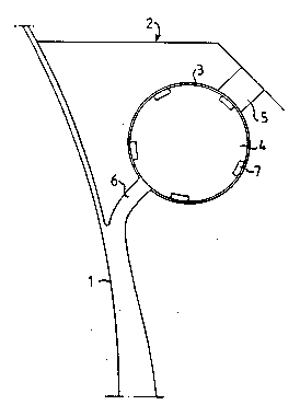
A device for dewatering a pulp suspension, comprising an
open-work movable surface (1) for forming and dewatering a pulp web. In
an inlet (2) for the pulp suspension to the movable surface (1), a
cylindric chamber (3) is located which encloses a rotatable
cylindric rotor (4), the shaft of which extends transverse to the
flow direction of the pulp. The rotor (4) is provided on its surface
with a plurality of crosswise arranged channels (7). The pulp is
forced to flow from an inlet (2) in the chamber (3) through the
channels (7) to an outlet (6) located on the opposite side of the
chamber (3).

Revendications

Note : Les revendications sont présentées dans la langue officielle dans laquelle elles ont été soumises.


WO 93/04234 PCT/SE92/00469
Claims
1. A device for dewatering a pulp suspension, compris-
ing an open-work movable surface (1) for forming and
dewatering a pulp web, and an inlet (2) for the pulp susp-
ension to the movable surface (1), c h a r a c t e r -
i z e d i n that in said pulp inlet (2) a rotatable
cylindric rotor (4) is located which with its shaft extends
transverse to the flow direction of the pulp and the
length of which substantially corresponds to the width
of the movable surface (1), that the rotor (4) on its
surface is provided with a plurality of cross-wise arr-
anged channels (7), and that the rotor (4) is enclosed
by a cylindric chamber (3), which has an inlet (5) and
an outlet (6) located substantially directly in front
of each other, so that the pulp is forced to flow through
the channels (7).
2. A device as defined in claim 1, c h a r a c t e r -
i z e d i n that the rotor (4) is arranged for slow
rotation, continuous or reversible.
3. A device as defined in claim 1 or 2, c h a r a c t -
e r i z e d i n that the channels (7) are arranged
helicoidally.
4. A device as defined in any one of the preceding
claims, c h a r a c t e r i z e d i n that the
channels (7) at their crossings form a substantially
right angle with one another.
5. A device as defined in any one of the preceding
claims, c h a r a c t e r i z e d i n that the rotor
(4) is rotatable at a speed of 1-20 rpm.

WO 93/04234 PCT/SE92/00469
6. A device as defined in any one of the preceding claims,
c h a r a c t e r i z e d i n that the diameter of the rotor (4)
is 50-100 mm.
7. A device as defined in any one of the preceding claims,
c h a r a c t e r i z e d i n that the outlet (6) of the
chamber (3) communicates via an outer return line (8, 9) with the
inlet (5) of the chamber (3) for circulation of a portion of the
pulp flow.

Description

Note : Les descriptions sont présentées dans la langue officielle dans laquelle elles ont été soumises.

W093/042~ 1 211~13 D PCT/SE92/0~69
Device for dewatering a pulp suspension
This invention relates to a device for dewatering a pulp
suspension. It comprises an open-work movable surface for
forming and dewatering the pulp suspension, an inlet
for the pulp suspension and an outlet for the dewatered
pulp.
The pulp suspension is supplied with a relatively low
concentration, usually 3-5~, and is formed on the open-
-work movable surface, which consists, for example, of
a perforated rollj through which liquid is sucked and
pressed off. Such presses usually comprise two perforated
rolls, which form between themselves a nip for pressing ;-
off liquid. The pulp normally is dewatered to a concen-
tration Or 35-50%.
A large problem at dewatering is that, due to low flow ~-
rate, flocculation (lump formation) of the pulp easily
occurs when the pulp suspension is being supplied to
the concentrator. The pulp-suspension, thus, is suppli~d
through a pipe line, in which the flow must be adapted
to the capacity of the concentrator. At the subsequent
pressing between the rolls, the fibres in these fibre
lumps are subjected to a pressing force higher than on
the remaining fibres, which can cause the fibres to be
crushed. This has a negative effect on the pulp quality
and cannot be compensated for in subsequent processing
steps.
-
The floccu~ation problem can be reduced by lowering the
- pulp concentration. Then, instead, the fibre losses in-
crease and a greater liquid amount nust be removed, at
the same time as the dewatering zone increase~ in length.
.

W093/042~ PCT/SE92/0~6~
c~ e
According to the present invention, the aforesaid problem
is eliminated in that the pulp inlet to the concentrator
is formed so that the supply takes place at a higher rate
by means of cross-wise arranged channels. Turbulence is
thereby brought about in the suspension, so that floccul- ~-
ation is prevented or lumps formed are broken up. In
certain cases it is even possible to increase the pulp
concentration to sbout 8%, without inconvenience.
~ :
The characterizing festures of the invention become app-
srent from the sttsched claims.
The invention is described in greater detsil in the foll-
owing, with reference to the accompanying drawings, in
which
Fig. 1 shows a pulp inlet to a concentrstor sccording
~to the invention,
~ig. 2 shows the surface o~ a rotor provided in the
pulp inlet,
Fig. 3 shows a detsil of the rotor surfsce according
~to a section III-III in Fig. 2,
Fig. 4 shows sn slternative configuration of the pulp
inlet.
Fig. S shows an alternative configuration of the rotor surface.
The device comprises an open-work movable surface 1, on
which the pulp suspension is intended to be formed. The
movable surface can be a perforated roll, wire or the
like. A pulp inlet 2 is provided for the supply Or the
suspension. The pulp inlet 2 is formed with a cylindric
chamber 3, which encloses a cylindric rotor 4 rotatable
about it5 shaPt. The chamber 3 and rotor 4 are located
transversely to the flow direction of the pulp and have
a length substantially corresponding to the width of the
movable surface 1. The chamber 3 i~ provided with an
inlet 5 and an outlet 6 located substantially directly
in front of each other.

W093/W2~ 2~ ~ 41~ ~ PCT/SE92/00469
The cylindric rotor 4 is provided on its surface with a
plurality of cross-wise arranged channels 7. The channels
suitably are arranged helicoidally with opposedpitch
angles. The channels can be arranged so that the crossings
form a right angle or nearly a right angle. Due to the
fact, that the rotor 4 is enclosed with a small clearing
by the chamber 4, the pulp suspension is forced to flow
through the channels 7.
The rotatable rotor 4 suitably rotates at a low rotation
speed, for example 1-20 rpm. The driving of the rotator
should be reversible. The rotor diameter can be 50-100 mm.
The channels are to be dimensioned so that the pulp
suspension flows at a su~ficient rate. The cross section of the
channels 7 can ~e of different design, for instance with rectangular
(fig 2 and 3) or triangular cross section (fig 5). A suitable size of
rectangular channels can be a width of 2-10 mm, preferably 3-7 mm, and
a depth of 2-8 mm, preferably 3-6 mm.
The device operates as follows.
The pulp suspension is supp.l.ied through the pulp inlet 2, whereby the pulp
flows via the inlet 5 of the chamber 3 in~o the channels 7, passes through
the~ same and flows out through the outlet 6 of the chamber 3. The outlet
6 communicates directly with the movable surface 1.
The pulp flows through the channels 7 at a high rate, which
at every crossing between the channels 7 is increa,sed
;instantaneously and thereby gives rise to intensive turb-
ulen~ce.~Flocculation of the pulp is thereby prevented,
and lumps already formed are broken up. Due to the rotation
of the rotor 4 about its shaft at a low speed of rotation,
continously or reversed, the flow direction through each
channel 7`changes periodically. Clogging of the channels
is thereby prevented. The rotor speed æhall be so low in
relation to the flow rate of the pulp through the channels
7, that the flow in one direction or the other about ;~

W093/042~ PCT/SE92/OW69
2~ 3e :~
the rotor 4 is of substantially equal size. The rotor
thereby is not subjected to uneven load, and at the same
time the ~ormation of fibre lumps is prevented in an
optimum manner.
According to the embodiment shown in Fig. 4, an outer
return line 8,9 is coupled between the outlet 6 snd inlet
5 of the chamber 3. In this line 8,9 a pump 10 is located.
This arrangement has the obje~tto maintain in the channels
7 a flow rate higher than correæponding to the capacity
of the concentrator. A portion of the pulp flow is then
circulated through the line 8,9 from the outlet 6 to the
inlet 5. In this way, a homogenous flow of pulp free
from fibre lumps to the formation zone on the movable .
surface 1 is ensured, irrespective of the capacity of
the concentrator.
The invention, of course, is not restricted to the embod-
iments described and shown, but can be varied within the
scope of the invention idea.

Dessin représentatif
Une figure unique qui représente un dessin illustrant l'invention.
États administratifs

2024-08-01 : Dans le cadre de la transition vers les Brevets de nouvelle génération (BNG), la base de données sur les brevets canadiens (BDBC) contient désormais un Historique d'événement plus détaillé, qui reproduit le Journal des événements de notre nouvelle solution interne.

Veuillez noter que les événements débutant par « Inactive : » se réfèrent à des événements qui ne sont plus utilisés dans notre nouvelle solution interne.

Pour une meilleure compréhension de l'état de la demande ou brevet qui figure sur cette page, la rubrique Mise en garde , et les descriptions de Brevet , Historique d'événement , Taxes périodiques et Historique des paiements devraient être consultées.

Historique d'événement

Description Date
Inactive : CIB de MCD 2006-03-11
Le délai pour l'annulation est expiré 1995-12-25
Demande non rétablie avant l'échéance 1995-12-25
Réputée abandonnée - omission de répondre à un avis sur les taxes pour le maintien en état 1995-06-26
Inactive : Demande ad hoc documentée 1995-06-26
Demande publiée (accessible au public) 1993-03-04

Historique d'abandonnement

Date d'abandonnement Raison Date de rétablissement
1995-06-26
Titulaires au dossier

Les titulaires actuels et antérieures au dossier sont affichés en ordre alphabétique.

Titulaires actuels au dossier
SUNDS DEFIBRATOR INDUSTRIES AKTIEBOLAG
Titulaires antérieures au dossier
ALF LINDSTROM
Les propriétaires antérieurs qui ne figurent pas dans la liste des « Propriétaires au dossier » apparaîtront dans d'autres documents au dossier.
Documents

Pour visionner les fichiers sélectionnés, entrer le code reCAPTCHA :


Pour visualiser une image, cliquer sur un lien dans la colonne description du document. Pour télécharger l'image (les images), cliquer l'une ou plusieurs cases à cocher dans la première colonne et ensuite cliquer sur le bouton "Télécharger sélection en format PDF (archive Zip)" ou le bouton "Télécharger sélection (en un fichier PDF fusionné)".

Liste des documents de brevet publiés et non publiés sur la BDBC .

Si vous avez des difficultés à accéder au contenu, veuillez communiquer avec le Centre de services à la clientèle au 1-866-997-1936, ou envoyer un courriel au Centre de service à la clientèle de l'OPIC.


Description du
Document 
Date
(aaaa-mm-jj) 
Nombre de pages   Taille de l'image (Ko) 
Abrégé 1993-03-03 1 46
Revendications 1993-03-03 2 51
Dessins 1993-03-03 2 56
Description 1993-03-03 4 178
Dessin représentatif 1998-05-25 1 4
Taxes 1994-01-23 1 40
Rapport d'examen préliminaire international 1994-01-23 10 184