Sélection de la langue

Search

Sommaire du brevet 2115616 

Énoncé de désistement de responsabilité concernant l'information provenant de tiers

Une partie des informations de ce site Web a été fournie par des sources externes. Le gouvernement du Canada n'assume aucune responsabilité concernant la précision, l'actualité ou la fiabilité des informations fournies par les sources externes. Les utilisateurs qui désirent employer cette information devraient consulter directement la source des informations. Le contenu fourni par les sources externes n'est pas assujetti aux exigences sur les langues officielles, la protection des renseignements personnels et l'accessibilité.

Disponibilité de l'Abrégé et des Revendications

L'apparition de différences dans le texte et l'image des Revendications et de l'Abrégé dépend du moment auquel le document est publié. Les textes des Revendications et de l'Abrégé sont affichés :

  • lorsque la demande peut être examinée par le public;
  • lorsque le brevet est émis (délivrance).
(12) Brevet: (11) CA 2115616
(54) Titre français: ENSEMBLE CORNIERE/GLISSIERE ET CADRE MUNI DE CET ENSEMBLE
(54) Titre anglais: CORNER ASSEMBLY AND FRAME COMPRISING SUCH ASSEMBLY
Statut: Périmé et au-delà du délai pour l’annulation
Données bibliographiques
(51) Classification internationale des brevets (CIB):
  • E06B 01/12 (2006.01)
  • E06B 01/36 (2006.01)
  • E06B 09/52 (2006.01)
(72) Inventeurs :
  • GUILLEMET, GUY (Canada)
(73) Titulaires :
  • BAY MILLS LTD.
(71) Demandeurs :
  • BAY MILLS LTD. (Canada)
(74) Agent: SMART & BIGGAR LP
(74) Co-agent:
(45) Délivré: 2004-04-20
(22) Date de dépôt: 1994-02-14
(41) Mise à la disponibilité du public: 1995-03-17
Requête d'examen: 2001-01-16
Licence disponible: S.O.
Cédé au domaine public: S.O.
(25) Langue des documents déposés: Anglais

Traité de coopération en matière de brevets (PCT): Non

(30) Données de priorité de la demande:
Numéro de la demande Pays / territoire Date
08/122,887 (Etats-Unis d'Amérique) 1993-09-16

Abrégés

Abrégé anglais


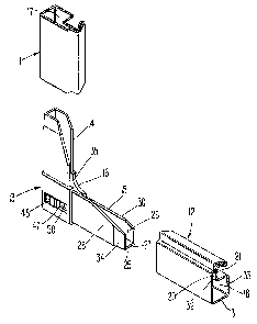
A corner assembly and frame comprising such
assembly is provided, for holding a screen or the
like, in which the corner assembly has a pair of
arms disposed to be connected to frame side members,
preferably by being telescopically received therein,
with a frame generally having such corner assemblies
at corners thereof, for facilitating retaining the
frame assembly, which is a removable assembly,
inside a fixed frame at the periphery of a window.
Each corner assembly includes a slide member carried
in a slideway, which slide member carries a
retaining protrusion extending therefrom, and with
the slide member having a manually engageable
button, movable button, movable longitudinally, to
move the slide member and its protruding button
between two positions, one position of which is an
extended position for the retaining protrusion, and
another position of which is a retracted position
therefor. In the extended position of the retaining
protrusion, the protrusion is adapted to engage
within a recess of a fixed frame member of a window.

Revendications

Note : Les revendications sont présentées dans la langue officielle dans laquelle elles ont été soumises.


-7-
CLAIMS:
1. A frame for a screen or the like, comprising a
plurality of side members and a plurality of corner
assemblies; with each such corner assembly comprising a
corner connector having a corner junction and pair of
connector arms disposed at approximately 90° relative to
each other and in telescopic connected relation with a
plurality of side members; with said connector arms being
spaced apart from each other by said corner junction; with
said corner junction including an exterior surface not in
telescopic connected relation with a said side member; with
the corner connector having a slideway therein, disposed
parallel to, and at least partially within one of its said
arms; with a slide member carried in said slideway, in
sliding engagement therewith between extended and retracted
positions therein, with said slide member having a retaining
protrusion extending therefrom, in a direction generally
parallel to said slideway; said retaining protrusion
extending in protruding relation beyond said corner
connector in the extended position of said slide member and
being substantially entirely disposed in retracted relation
within said corner connector in the retracted position of
said slide member; and including a retaining button carried
by said slide member and being adapted to be manually
engaged by a user for moving said slide member between
extended and retracted positions thereof, including an
elongated opening in the corner junction, generally parallel
with said slideway and connecting said slideway with the
exterior of said corner junction, and with said retaining
button extending from said slide member to the exterior of
the corner junction through said opening.
2. The frame of claim 1, including an elongated
opening in the corner connector, generally parallel with

-8-
said slideway and connecting said slideway with the exterior
of said corner connector, and with said retaining button
extending from said slide member to the exterior of the
corner connector through said opening, for traversal of said
retaining button along said opening as said slide member
moves between retracted and extended positions.
3. The frame of claim 1, wherein said corner assembly
is comprised of only the following three separate parts;
a) the corner connector;
b) the slide member; and
c) the button.
4. The frame of claim 2, with said retaining button
having a face and shank; and with the shank extending
through said opening and being carried by said slide member.
5. The frame of claim 4, wherein the face of said
retaining button includes means for facilitating manual
engagement thereof.
6. The frame of claim 1, wherein said corner assembly
is comprised of thermoplastic components.
7. The frame of claim 1, wherein said retaining
protrusion is of unitary construction with said slide
member.
8. The frame of claim 1, including an elongated
opening in the corner connector, generally parallel with
said slideway and connecting said slideway with the exterior
of said corner connector, and with said retaining button
extending from said slide member to the exterior of the
corner connector through said opening, for traversal of said
retaining button along said opening as said slide member

-9-
moves between retracted and extended positions; with said
retaining button having a face and shank; and with the shank
extending through said opening and being carried by said
slide member; wherein the face of said retaining button
includes means for facilitating manual engagement thereof;
wherein said corner assembly is comprised of thermoplastic
components; wherein said corner assembly is comprised of the
following three separate parts;
a) the corner connector;
b) the slide member;
c) the retaining button; and
wherein said retaining protrusion is of unitary construction
with said slide member.
9. A corner assembly for a frame for a screen or the
like, with the assembly comprising a corner connector having
a corner junction and a pair of connector arms disposed at
approximately 90° relative to each other; with said
connector arms being spaced apart from each other by said
corner junction, and with said corner junction including at
least one exterior face, with the corner connector having a
slideway therein disposed parallel to, and at least
partially within one of its said arms; with a slide member
carried in said slideway in sliding engagement therewith,
between extended and retracted positions therein; with said
slide member having a retaining protrusion extending
therefrom, in a direction generally parallel to said
slideway; said protrusion extending in protruding relation
beyond said corner connector in the extended position of
said slide member and being substantially entirely disposed
in retracted relation within said corner connector in the
retracted position of said slide member; and including a

-10-
retaining button carried by said slide member and being
adapted to be manually engaged by a user for moving said
slide member between extended and retracted positions
thereof, including an elongated opening in the exterior face
of the corner junction, generally parallel with said
slideway and connecting said slideway with the exterior of
said corner junction, and with said retaining button
extending from said slide member to the exterior of the
corner junction through said opening.
10. The assembly of claim 9, including an elongated
opening in the corner connector, generally parallel with
said slideway and connecting said slideway with the exterior
of said corner connector, and with said retaining button
extending from said slide member to the exterior of the
corner connector through said opening, for traversal of said
retaining button along said opening as said slide member
moves between retracted and extended positions.
11. The assembly of claim 9, wherein said corner
assembly is comprised of only the following three separate
parts;
a) the corner connector;
b) the slide member; and
c) the retaining button.
12. The assembly of claim 9, with said retaining
button having a face and shank; and with the shank extending
through said opening and being carried by said slide member.
13. The assembly of claim 12, wherein the face of said
retaining button includes means for facilitating manual
engagement thereof.

-11-
14. The assembly of claim 9, wherein said corner
assembly is comprised of thermoplastic components.
15. The assembly of claim 9, wherein said retaining
protrusion is of unitary construction with said slide
member.
16. The assembly of claim 9, including an elongated
opening in the corner connector, generally parallel with
said slideway and connecting said slideway with the exterior
of said corner connector; and with said retaining button
extending from said slide member to the exterior of the
corner connector through said opening, for traversal of said
retaining button along said opening as said slide member
moves between retracted and extended positions; with said
retaining button having a face and shank; and with the shank
extending through said opening and being carried by said
slide member; wherein the face of said retaining button
includes means facilitating manual engagement thereof;
wherein said corner assembly is comprised of thermoplastic
components; wherein said corner assembly is comprised of the
following three separate parts;
a) the corner connector;
b) the slide member;
c) the retaining button; and
wherein said protrusion is of unitary construction with said
slide member.

Description

Note : Les descriptions sont présentées dans la langue officielle dans laquelle elles ont été soumises.


r-
2i15~~.6
-1 -
CORNER ASSEMBLY AND FRAME
COMPRISING SUCH ASSEN~LY
BACKGROUND OF THE INVENTION
In the art of window manufacture, it is known
to provide windows with fixed frames, in which
movable frames are disposed. The movable frames may
carry screening therein, for ventilation purposes.
It is also known, in the art of window
manufacture, that movable frame assemblies are
disposed within fixed frame assemblies, for raising
or lowering screens or the like, for pivotally
moving screens or the like, for facilitating
placement, cleaning, or for any other purposes
and/or for adjustment of the position of the movable
frame assembly that comprises the screen or the
like, within the fixed frame.
One example of a prior art type of frame corner
bracket is disclosed in U.S. Patent Des. 307,078
dated April 10, 1990, which represents a corner
bracket for holding an insect screen, or the like,
that may be inserted into an exterior frame.
'SHE PRESENT INVENTION
The present invention is directed toward
providing a frame assembly that includes a corner
assembly for an insect screen, or the like, in which
means are provided for efficiently providing a
retaining mechanism for retaining the movable frame
assembly into a fixed frame, for any of various
purposes, such as for securement of the movable
frame in a retained position, for facilitating a
desired position of the movable frame assembly
relative to a fixed frame, etc.

CA 02115616 2003-06-02
60973-646
-la-
The invention provides a frame for a screen or the
like, comprising a plux:~ality of side members and a plurality
of corner assemblies; with each such corner assembly
comprising a corner coxaneector having a corner junction and
pair of connect=or arms disposed at approximately 90°
relative to each other and in telescopic connected relation
with a pluralit:.y of sic~.e members; with said connector arms
being spaced apart from each other by said corner junction;
with said corner junction .including an exterior surface not
in telescopic connectec .relation with a said side member;
with the corner connector having a slideway therein,
disposed paral7_el to, a.nc~ at least partially within one of
its said arms; with a slide member carried in said slideway,
in sliding engagement the=rewith between extended and
retracted positions therein, with said slide member having a
retaining protrusion ex.tendi.ng therefrom, in a direction
generally parallel to said slideway; said retaining
protrusion extending in protruding relation beyond said
corner connector in the extended position of said slide
member and being substantially entirely disposed in
retracted relation within said corner connector in the
retracted position of. said .slide member; and including a
retaining button carried by said slide member and being
adapted to be manually engaged by a user for moving said
slide member between extended and retracted positions
thereof, including an elongated opening in the corner
junction, generally parallel with said slideway and
connecting said slideway with the exterior of said corner
junction, and with said retaining button extending from said
slide member to the exterior of the corner junction through
said opening.
The :invention also provides a corner assembly for
a frame for a screen or the like, with the assembly

CA 02115616 2003-06-02
60973-646
-lb--
comprising a corner connector having a corner junction and a
pair of connector arms disposed at approximately 90°
relative to each other; with said connector arms being
spaced apart from each other by said corner junction, and
with said corner junction including at least one exterior
face, with the corner connector having a slideway therein
disposed paral=_el to, and at :Least partially within one of
its said arms; with a slide member carried in said slideway
in sliding engagement therewith, between extended and
retracted positions there°_:in; wi_th said slide member having a
retaining protrusion extending therefrom, in a direction
generally parallel to said slideway; sa:ici protrusion
extending in protruding relation beyond said corner
connector in the extended position of said slide member and
being substantially entire:ly~ disposed in retracted relation
within said corner connector in the retracted ,position of.
said slide member; and including a retaining button carried
by said slide member and being adapted to be manually
engaged by a u~~er for moving said slide member between
extended and retracted positions thereof, including an
elongated opening .in the exterior face of the corner
junction, generally parallel with said slideway and
connecting said slideway with the exterior of said corner
junction, and with said retaining button extending from raid
slide member to the exterior of the corner junction through
said opening.

~1~5~16
-2-
Accordingly, it is a primary object of this
invention to provide a novel corner assembly and
frame comprising such assembly, in which a frame
assembly for a screen or the like is provided with a
slidable locking mechanism.
It is another object of this invention to
provide a corner assembly for a removable frame, in
accordance with the foregoing object.
It is another object of this invention to
provide an efficient retaining mechanism of the
slide type, for use with a corner assembly for a
movable or removable frame assembly for a screen or
the like.
Other objects and advantages of the present
invention will be readily understood, upon a reading
of the following brief descriptions of the drawing
figures, detailed descriptions of the preferred
embodiments, and the appended claims.
BRTEF DESCR~;PTIONS OF THE DRAWING FIGURES
Fig. 1 is a fragmentary, perspective, exploded
view of the corner assembly of this invention and
portions of side members of a movable or removable
frame, to which the corner assembly is connected.
Fig. 2 is a fragmentary front view of a lower
left corner of a movable or removable screen frame
assembly, including a corner assembly, in accordance
with this invention.
Fig. 3~is a horizontal, sectional view taken
through the corner assembly shown in Fig. 2,
generally along the line III-III of Fig. 2, with the
retaining protrusion of the corner assembly being
shown disposed in retaining relation in a portion of
a fixed frame assembly, that in turn, is illustrated
in phantom in Fig. 3.

2115616
-3-
Fig. 4 is a vertical sectional view taken
through the corner assembly of Fig. 2, generally
along the line IV-IV of Fig. 2.
DETAILED DESCRIPTIONS OF THE PREFERRED EMBODIMENTS
Referring now to the drawings in detail,
reference is first made to Fig. 1, wherein the
movable frame assembly that is shown in Fig. 2, is
seen as comprising a pair of side frame members 11
and 12, generally disposed about 90° apart, and a
corner assembly 13.
The corner assembly 13 has a pair of connector
arms 14, 15 extending outwardly from a corner
connector portion 16, generally at 90° relative to
each other as shown, for facilitating telescopic
receipt of the arms 14, 15, into corresponding
channels or other openings 17, 18, respectively, of
the frame side members 11, 12, which telescopic
receipt of such arms 14, 15 is thus shown in the
dotted line showing for the arms in Fig. 2.
The cross-sectional configuration for the frame
side members 11, 12, may be of the roll formed or
extruded U-shaped construction 20, 21 shown for
example, in Fig. 1, for the frame
side member 12, with the channel 18 opening upward,
as shown, for receipt therein of a peripheral bead
22 for a screen 23 (see Fig. 2) therein, as shown.
It will be understood that there will preferably be
four such~frame side members 11, 12, comprising the
periphery of the movable or removable frame 10, with
retaining corner assemblies 13, preferably at each
of the four corners thereof.
Each arm 14, 15 of the corner assembly 13 will
preferably also have a U-shaped configuration 25,
opening into a channel 26, as shown in Fig. 1,

21156.6
-4-
including a base 27, arms 28,30, adapted to be
resiliently received in gripping telescopic relation
within side members 11, 12. In the particular
arrangement shown, the portions 27, 28 and 30 of the
arm 15 are respectively received within zones 31,
32, 33 of frame side member 12 as shown in Fig. 1.
It will be noted that the outer end of each of arm
portions 27, 28 and 30 is chamfered as shown at 34.
It will also be understood that the arm 14 is
constructed generally similar to that of 15, as
shown, for likewise telescopic connection to the
frame side member 11.
At the left end of the U-shaped opening 26 of
the arm 15, and continuing into the interior 35 of
the corner junction 16, is a slideway 36, as shown
in Fig. 4. The slideway 36 houses therein a slide
member 37, movable therein between the full line
position therefor shown in Fig. 3 and the phantom
line position therefor 38, also shown in Fig. 3,
with the slide member 37 being of generally
rectangular configuration, as shown in dotted lines
in Fig. 2.
Fixedly carried on the left end of the slide .
member 37, and preferably unitary therewith, is a
retaining protrusion 38, such that when the slide
member 37 has its right-most end as shown in Fig. 3
in the phantom line position 38 illustrated in Fig.
3, the left-most end 40 of the retaining protrusion
38~is either even with the left-most end 41 of the
corner connector 16, or is slightly sunken (not
shown), relative thereto, such that it does not
protrude outwardly thereof. ,When the slide member
37 is in the full line position therefor shown in
Fig. 3, the retaining protrusion 38 is in the
extended position shown in Fig. 3, adapted to be

2~~~~~~
-5-
engaged within a recess 42 in a fixed frame member
43, preferably disposed about the movable or
removable frame member 10, in which the movable or
removable frame member 10 will preferably be
received.
Alternatively, 'the slide member 37 could be of
multiple-piece construction, such as in the form of
a two-piece snap-in arrangement, not shown herein.
A slot 44 is provided in the slide member 37,
in which a pair of locking tangs 45, 46 of a button
47 are received, in resilient engagement therewith,
as shown in Fig. 3, with the button 47 having a
manually engageable, slightly protruding and/or
knurled outer surface 48, for engagement by
preferably the thumb of a user, for sliding the
slide member 37 within the slideway 36, by engaging
the surface 48 of the button 47 and moving the same
leftward and rightward within its guideway 50 as
shown in Fig. 3.
Thus, it will be seen that the slide member 37
moves parallel with and within the slideway 36, upon
movement of the button 47 within its guideway 50,
also parallel therewith.
It will also be seen that the corner assembly
is preferably constructed of only three components;
namely, the corner connector 16 with its extending
arms 14 and 15 comprising one component, with the
slide member 37 comprising another component, and
with the retaining button 47 comprising the third
component. Alternatively, the corner assembly could
be made of a fewer or greater number of components.
It will also be understood that the device of the
present invention ma.y be constructed such that the
components of the corner assembly are of
thermoplastic construction, which lends itself to

2~1~~16
-6-
ready slidability of the sliding components within
their slideways/guideways; that the corner
assemblies are readily adaptable for insertion into
side frame members that are of any compatible
construction, such as aluminum, steel, vinyl or
other appropriate materials, and which lend
themselves to adaptation to various color schemes,
or the like.
It will further be understood that various
modifications may be made in the details of
constructions, as well as in the use
and operation of the components of the present
invention, all within the spirit and scope of the
invention as defined in the appended claims.

Dessin représentatif
Une figure unique qui représente un dessin illustrant l'invention.
États administratifs

2024-08-01 : Dans le cadre de la transition vers les Brevets de nouvelle génération (BNG), la base de données sur les brevets canadiens (BDBC) contient désormais un Historique d'événement plus détaillé, qui reproduit le Journal des événements de notre nouvelle solution interne.

Veuillez noter que les événements débutant par « Inactive : » se réfèrent à des événements qui ne sont plus utilisés dans notre nouvelle solution interne.

Pour une meilleure compréhension de l'état de la demande ou brevet qui figure sur cette page, la rubrique Mise en garde , et les descriptions de Brevet , Historique d'événement , Taxes périodiques et Historique des paiements devraient être consultées.

Historique d'événement

Description Date
Le délai pour l'annulation est expiré 2011-02-14
Lettre envoyée 2010-02-15
Inactive : CIB de MCD 2006-03-11
Accordé par délivrance 2004-04-20
Inactive : Page couverture publiée 2004-04-19
Inactive : Taxe finale reçue 2004-01-14
Préoctroi 2004-01-14
Un avis d'acceptation est envoyé 2003-07-21
Lettre envoyée 2003-07-21
Inactive : Approuvée aux fins d'acceptation (AFA) 2003-07-10
Modification reçue - modification volontaire 2003-06-02
Inactive : Dem. de l'examinateur par.30(2) Règles 2002-12-02
Modification reçue - modification volontaire 2001-02-06
Lettre envoyée 2001-01-26
Inactive : Renseign. sur l'état - Complets dès date d'ent. journ. 2001-01-26
Inactive : Dem. traitée sur TS dès date d'ent. journal 2001-01-26
Exigences pour une requête d'examen - jugée conforme 2001-01-16
Toutes les exigences pour l'examen - jugée conforme 2001-01-16
Demande publiée (accessible au public) 1995-03-17

Historique d'abandonnement

Il n'y a pas d'historique d'abandonnement

Taxes périodiques

Le dernier paiement a été reçu le 2004-01-23

Avis : Si le paiement en totalité n'a pas été reçu au plus tard à la date indiquée, une taxe supplémentaire peut être imposée, soit une des taxes suivantes :

  • taxe de rétablissement ;
  • taxe pour paiement en souffrance ; ou
  • taxe additionnelle pour le renversement d'une péremption réputée.

Les taxes sur les brevets sont ajustées au 1er janvier de chaque année. Les montants ci-dessus sont les montants actuels s'ils sont reçus au plus tard le 31 décembre de l'année en cours.
Veuillez vous référer à la page web des taxes sur les brevets de l'OPIC pour voir tous les montants actuels des taxes.

Historique des taxes

Type de taxes Anniversaire Échéance Date payée
TM (demande, 4e anniv.) - générale 04 1998-02-16 1997-10-24
TM (demande, 5e anniv.) - générale 05 1999-02-15 1999-02-04
TM (demande, 6e anniv.) - générale 06 2000-02-14 2000-01-21
Requête d'examen - générale 2001-01-16
TM (demande, 7e anniv.) - générale 07 2001-02-14 2001-01-19
TM (demande, 8e anniv.) - générale 08 2002-02-14 2002-01-21
TM (demande, 9e anniv.) - générale 09 2003-02-14 2003-01-24
Taxe finale - générale 2004-01-14
TM (demande, 10e anniv.) - générale 10 2004-02-16 2004-01-23
TM (brevet, 11e anniv.) - générale 2005-02-14 2005-01-20
TM (brevet, 12e anniv.) - générale 2006-02-14 2006-01-19
TM (brevet, 13e anniv.) - générale 2007-02-14 2007-01-17
TM (brevet, 14e anniv.) - générale 2008-02-14 2008-01-18
TM (brevet, 15e anniv.) - générale 2009-02-16 2009-01-19
Titulaires au dossier

Les titulaires actuels et antérieures au dossier sont affichés en ordre alphabétique.

Titulaires actuels au dossier
BAY MILLS LTD.
Titulaires antérieures au dossier
GUY GUILLEMET
Les propriétaires antérieurs qui ne figurent pas dans la liste des « Propriétaires au dossier » apparaîtront dans d'autres documents au dossier.
Documents

Pour visionner les fichiers sélectionnés, entrer le code reCAPTCHA :


Pour visualiser une image, cliquer sur un lien dans la colonne description du document (Temporairement non-disponible). Pour télécharger l'image (les images), cliquer l'une ou plusieurs cases à cocher dans la première colonne et ensuite cliquer sur le bouton "Télécharger sélection en format PDF (archive Zip)" ou le bouton "Télécharger sélection (en un fichier PDF fusionné)".

Liste des documents de brevet publiés et non publiés sur la BDBC .

Si vous avez des difficultés à accéder au contenu, veuillez communiquer avec le Centre de services à la clientèle au 1-866-997-1936, ou envoyer un courriel au Centre de service à la clientèle de l'OPIC.

({010=Tous les documents, 020=Au moment du dépôt, 030=Au moment de la mise à la disponibilité du public, 040=À la délivrance, 050=Examen, 060=Correspondance reçue, 070=Divers, 080=Correspondance envoyée, 090=Paiement})


Description du
Document 
Date
(aaaa-mm-jj) 
Nombre de pages   Taille de l'image (Ko) 
Dessin représentatif 1998-02-23 1 13
Revendications 2003-06-01 5 222
Dessin représentatif 2003-07-09 1 7
Description 2003-06-01 8 292
Abrégé 1995-05-19 1 27
Revendications 1995-05-19 5 504
Dessins 1995-05-19 2 163
Description 1995-05-19 6 610
Dessins 2001-02-05 2 41
Rappel - requête d'examen 2000-10-16 1 116
Accusé de réception de la requête d'examen 2001-01-25 1 179
Avis du commissaire - Demande jugée acceptable 2003-07-20 1 160
Avis concernant la taxe de maintien 2010-03-28 1 171
Correspondance 1994-03-10 3 86
Correspondance 2004-01-13 1 29
Taxes 1997-02-04 1 84
Taxes 1996-01-29 1 82