Note : Les descriptions sont présentées dans la langue officielle dans laquelle elles ont été soumises.
i~V~ 93/06316 PC'~'lAIJ92/00511
1
Title: "BUILDING PANEL AND BUILDINGS USING TF3E PANEL"
FIELD OF THE INVENTION
TI3TS INVENTION relates to building panels,
buildings and building systems using the panels. In
particular, the invention relates to ~a .' cored- or
-
ehannelled panel and systems which utilise the cored or
channelled character of the panel to erect buildings and
the like.
BACKGROUND OF THE INVENTION
Many factory formed panels are used in the
building industry by which to form a wall, roof, etc. in
a building. Systems employing modular units that are
prefabricated to enable creation of a range of
architecturally varied buildings are known. With all
such panels and ~ysteam~, effort is put into seeking to
reduce input material costs, to improve fabrication
techniques so as to xeduce production costs, and to
adapt the characf.eristics of the prefabricated elements
to reduce on-s~.te hand~:ing problems and make erection of
bu:i7.dings less dependent on skilled trades.
O~yT~CTS' OF THE INVENTION
The pfesent in~rention has as its object to
further improve building systems with a novel form of
panel t~ be used in erection of buildings which panel
~ro~r~de~ ~~r improved constructions using the panel.
Other objects ahd various advantages of the
present inventi~n wil3. hereinafter become apparent.
~~SCR~F'S~OI3 (~F THE I1~1V~NTION
The invention achieves its object in the
provision of a building panel which may be used in the
construction df flogs, walls; roofs and ceilings of
b~uildinqs compra,sizxg s
spaced apart ffirst and second facing
sheets; and
a core thenebetween;
'W~ 93/Ob3~G ~G'~"/~,U921~0~11
~~,,
2
the first and second sheets being bonded to
the core;
characterised in that
the core being crossed in at least one
direction by a plurality of channels therethrough;. _'
.-
the channels being dimensioned to pass or
receive therein structural building elements or
concrete.
In addition to the above defined panel, the
invention prov:i.des novel building structures utilising
the panel as will be described hereinafter.
Further, the invention also provides novel
methods of establishing buildings utilising the above
described panels which will also be described in greater
detail hereinafter:
The facing sheets above might be fibre cement
sheets; plasterboard. sheets, plywood; and the like, with
or without surface treatments suited to the use of the
panel. The facing sheets may be chosen for their
stxuct~ral c'haracteristic~ when a stressed skin effect
is desired in ~.he panel: The thickness of the facing
sheets wi7L1 de~asz~d on the use of the panel, the material
of the si~eet and what cgnstruction technique is used in
constructi~n of ~a bhild~;ng using the sheet:
The core ab~~e may tike ~ variety of forms,
depending can the application of the pane.. The core may
comprise a foam ir~fi31 which bas been carved out
internally to cr~atc channels. Tt may be composed of an
array of el~angate blocl~s of material such as foam which
are spaced :part to c~ea~te voids or channels
th~rebetween. Lt may be composed of an array of spaced
apart bl~cks of material, spaced to create channels
thexeb~t~reen overlaid with a ' sheet or layer of
inSUlat~.on material, such aS a heat insulating material,
3 5 such es plastic foam and the like . The aforesaid sheet
'WU 93d46316 ~ ~ ~ ~ ~ ~~ ~P~T/~U92/~51 ~
3
of insulation material is provided in a thickness suited
to the degree of insulation required and the material
which is chosen will be chosen for its insulation
characteristics. The aforesaid sheet of material might
substitute for one of the facing sheets aboue.' The -core
---
might be comprised of a spaced linear array of parallel
elongate spacers of a material such as steel in shapes
such as C~sections.
The channels above may be voids between blocks
1,0 ox~ lengths of core material or hollows cored out of a
block of material. The channels might have a width
equal to the width of the core, or they might extend
only part way across the core. The channels might be
provided in two directions across the panel to enable
inserts, passage of services, or f low of concrete
across the width of the panel as well as across its
height.
By use of the above panels, a building can be
erected wherein structural members recyuired to support
loads may be passed through selected channels of a panel
to engage wa.th other elements at opposite edges of the
pahel to establish a structural framework which is
walled in by the pane~.s. In establishing a wall with
the panel, timber ~~ steel may be passed through
ch~.nnels in the panel with the lower ends attached to a
v flour, of the like; and the upper end to a roof member
t~ crate a structural framework akin to what is now
used; with the v~x~tical members passed through the
channela of panels which fill out the wall. The panel
3p member can be fabricated with facing surfaces as desired
ah~ preferably the panels are faced with materials
providing a skin that can withstand stresses therein so
that the core of the panel may be a standard foam
material wherein channels may be established by spacing
blocks of foam ar they may be readily formed using a hot
~V~ 93!(D6316 PCTlAt19~1Q~0511
,~.,.,,,
4
wire or extrusion techniques, etc. The channels may be
parallel and arrayed across the width of the panel at
regularly repeated intervals in at least one direction
and modular construction techniques utilising the panels
can be adopted. The panels may be eonstruc_ted from an
assembly of materials, which materials are~ suited to a
builder's usual set of tools.
zn an alternate use of the panel, rather than
traversing the panel with lengths of timber, steel,
etc., to create the structural load bearing capability
of the wall or building frame work, the panels can be
used to establish a formwork with an exposed core into
which concrete may be poured to establish structural
strength akin to a hollow block construction as will be
hereinafter described i~ greater detail.
Tn a further technique with concrete the panel
is used in construction of a floor, ceiling or roof.
The panel is utilised in a manner which has it
performing the function of traditional formwork.
Concrete may be poured over the upper surface of a panel
with various of its voids exposed to permit concrete
f low therein to establish beams. The pour might be
cont.~nue~ci s~ a~ to establish a considerable slab with
beams thereunder. Reinforcing rods ~.y be added as will
2~ be described an greater detail belew.
~~tIRF DEGCRIPTLON OF I3~~nlIrlGS
The invention will now be .described with
reference to vari~us preferred embodiments as shown in
the accompanying dr~wings,,in which:
FTGS. 1; to 21 show various sections through
panels and ~!alls constructed in accordance with the
present invention wherein timber, steel and the like,
provides far 3oad bearing;
FIGS: 12 to 18 show various sections through
3~ panels and wails in another embodiment of the invention
1~7~ 93109~31~ :.~ . ' .~ ~:~ t~ PC.'T/AU92/O~i591
wherein concrete provides for load bearing;
FIG. 19 shows the manner of use of a panel in
accordance with the present invention so as to establish
a floor ceiling or roof ;
5 FIG. 20 shows an alternate panel ~t~pe andwhow
it is used; and
FIGS. 21 and 22 show sections through two
further embodiments of the panel.
The drawings are not to scale, being schematic
layouts to indicate the nature of the features of the
invention which give rive to its advantageous
attributes. Actual proportions will vary according to
engineering reguirements in any particular building. In
concrete Construction, the pattern of reinforcements
~,5 will'be varied to suit by construction engineers. irdhat
is 5.llustrated is presented merely to indicate the
nature of the advances in the art which are the subject
matter of this specification.
pREF~R~D F.~3OI~ITS
In FIG. 1 is shown a transverse section
through a panel 1.0 established between facing sheets 11
and 22 with spacers 13 leaving voids therebetween. The
spaces might ~e a fo~zn material and the sheets can be
an~r ~f the standard sheets such as plasterboard,
plywood, cement sheet, etc. The actual materials used
~rs~.l depend on application and factors such as nature of
use, wenviroz~~i~ntand loadin~s, and what additional
treatments might ~e planned, such as what decorative
sux°f,ace coatings aright be used. The f acing sheets might
~p be ~ c~mposite' built of layers selected fox their
respective properties and laminated for use in
produc~.ion of the panel. In some applications, the
facing sheets might be chosen for their sheet properties
,~~ ~ structural skin adding to the structural properties
of the assembled buildings. In other applications, the
'W~ 93/06316 P~'fAU92/00511
~'~ ~"'
6
facing sheets may only serve as formwork for a concrete
infill which is designed to meet structural
requirements. Those skilled in the art will appreciate
that the panel materials and dimensions might be varied
to accommodate a wide range of needs. ~ '
~._~-
In use of the panel of FIG. 1, the panels
might be put in place between splicing studs 14 and 15
at each end. The panel facing sheets overlap the
splicing stud which is received between the sheets at
the panel edge and suitable connectors or other means
might be applied to bond the two together. In the
discussion below with gegard to FIGS. 1 to 11 is set out
a use of the panel in an essentially timber framed
house. It will be appreciated by those skilled in the
art that steel or aluminium could be substituted for the
timber with erection of a building using the panels
being progressed .in essentially the same way.
In use of the panel la of FIG. 1, the spacers
may extend the full length of the panel. then a plastic
foam is used as a spacer, the Edam is readily removed at
the ends and timbers may be laid up therein to complete
a t~.mbdr frame therdin. The shear connector of FIG. 2
provides a c~nvenien~ means of interconnecting timber
f rame~rork .
In FIGo 2~ the shear connector 16 comprises a
web 17 between opposed plates 18~ and 19. The opposed
plates may be.:prouided with a pattern of holes 2~ for
the passage therethrough of nails or the like to fix the
shear connector l.6 between timber studs and plates to
3O frame a building as set out in FIGS. 3 and 4.
In FAG. 3 a vertical stud 23 is capped by a
shear connector 2l and a top plate 22 is laid thereover.
When connect~~s such as nails are in place the stud and
top plate are locked together. Ln FIG. 4, the shear
connector 24 does the same job between stud 26 and
'l~l~D 93/06316 PC.'T/AlJ~2/~451 i
bottom plate 25.
FIG. 5 is a horizontal section through a
corner of a building using the above described panels.
In putting up the building the panel 28 is stood at the
corner, in from the corner the thickness off acing sheet
31 of panel 27. The foam end stud of sheet 28 is
removed and a cyclone anchor rod 37 might be fitted in
place. Corner timber is then put in place and
conveniently two studs 32 and 33 can be used. Then
panel 30 is prepared with its foam end stud removed and
its f ace sheet 30 cut back to remove dotted length 29 so
that panel 27 might be put in place as illustrated. The
stud 34 can be put in place after any cyclone anchor rod
38, as required. The corner can be finished internally
with tape 35 over the joint, or by use of any desired
moulding, etc. The external joint might be sealed with
an angle moulding 36 as desired to cover over the joint
between facing sheet 3l on panel 27 and panel 28.
FIG. ~ is a horizontal section through a wall
showing how an internal panel 40 might meet an external
or ~ther internal wall perpendicularly: At the joi.nt~ a
stud 41 is put in place in panel 39. At the corner
where panel 9:0 is t~ b~ applied, a stud 42 can be nailed
to stud,4l. Then parcel 40 may be placed as illustrated
and fixed to the butt stud 42 by an suitab~.e meaa~= The
internal cor~xe~s 43 and 42 might be taped or otherwise
treated as above. When required; tie dos~n rods 45 and
46 may be put in place in voids in t~.e respective panels
39 and 40.~
3p: FIG. 7 is a vertical section through .a wall
~a~c with the: above described panel. The panel. 47 is
stood over a slab floor 48 extended to a roof 49. An
aa~chorcd reinforcement 50 projected cut of slab 48 is
connected to tie down fod 51 which is attached at 53 to
a top plate 54 carrying roof 49: At the base of the
Vb~~ 93/~D63~b ~C.T/A1J92/~0511
,..:...
2~.~.~J2c~
s
wall a bottom plate 55 is connected to vertical studs
(not shown) with shear connectors of the type described
with regard to FIG. 2. The bottom plate may overlay a
f lashing at the slab edge of the usual form to control
moisture at the bottom of the wall. Sealants might be
~.r
added as required. The eternal surface of panel 47
might be provided with any of the standard surface
finishes as desired.
FIG. 8 is a vertical section through a wall
above a windos~ opening. Panel 56 is cut back, or
extends to, the .window level to create an opening into
which a window 58 may be fitted. The foam studs of
panel 56 are broken out and a timber length 5? inserted.
The usual reveal 59 can then be put in place and the
window inserted: Any of the usual finishes might be
applied such as architrave 60 and external trim 61.
FIG. 9 is a vertical section through the wall
at the bass of the window. The panel 62 reaches to the
window sill, its internal foa~r studs are broken out, and
timber 63 is put in place. The reveal 64 is put in
place, the window 65 is fitted, and tri,Jms 66 and 67 may
be added:
FIB: 10 is a-vertical section through a wall
at the roof to illustrate the use of the above described
Panel in ~ single skin wall. In ~'IG. 10, panel 68 has
its foam studs broken away to f~rm an opening 70 in
which a ~eria~eter bean can be established. A beam 69
might be played abo~rc a dead tria~nner 71 beneath t~p
plates ?2 ~ arid 73, which can be tie~3 down to bottom
3 0 p~.ates , s lab base , etc . as described above . Spacers 7 4
might be put in plade to support the inner facing sheet
a~ the upper edge: A corner piece 76 may be fitted
beneath a ceiling sheet 75 on battens 77 beneath rafters
.~8 carrying roof truss 79 tied by straps 80 to the top
plates 7~ and 73.
. ~ ~ ~ ~ 1'~T/AU92/00511
'V6~O X3106316 c~
9
FIG. 11 is a vertical section through a wall
at the roof to illustrate the use of the above described
panel in a brick veneer wall. In FIG. 11, panel 81 is
internally located of an e~cternal brick wall 82. The
panel 81 is framed as is usual in a brick .veneer
construction to provide a structural framework. Top
plates 83 might be mounted together with steel beam 84
to create a perimeter beam.
The above described building is essentially a
timber framed construction utilising the panel of the
present invention. In the below described construction,
the building is essentially concrete so far as its
structural characteristics are concerned.
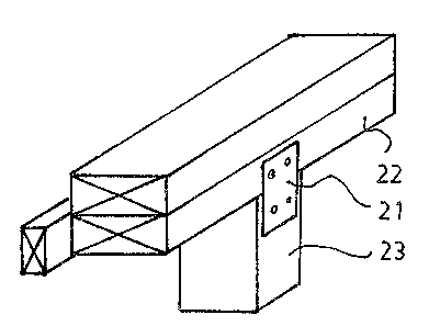
FIG. 12 illustrates a transverse section
through a panel 85 having the character set out above.
To join panels cr.annel connectors such as 86 may be
applied as required between the facing sheets of the
garael~at pointy around the panel. The channel connector
is shown an greater def.ail in FTG. 14. The voids 87 of
z0 this panel are filled with concrete as will be described
below in creating a building using the panel 85.
FIG. 13 is a transverse section through an
edge-~ca-edge connection of trao panels 88 and 89 with a
chaa~nel connector 90 therebetweeno Channel connect~rs
z5 ma:ght be applied along such an edge at 609 mm centres
and scxews car other suitable means might be used to join
the panels thereto a Af ter poura:ng concrete into the
voids, the screws might be removed.
FIG. 14 shows the feat~es of a channel
3p con~.ector 91 with a ~~ or C-shaped gross-section. Gide
plates 92 and 93 are ~t right anglesto web 94.
FIB: 15 is a vertical section through the base
~f a wall of a building. Panel 95 is stood over the
edge of a slab 96 which has a reinforcement 97, one end
35 98 ert~bedded in the footing of the slab 96 and the other
~vv~ ~3>ob~~6 ~crm~r~~ioos~~
2~.1~~2~
end 99 projected above into a void in panel 95. A rod
100 can be added in the void of the panel 95 to overlap
the end 99. 'When concrete is poured into the void 1010
the column is reinforced for all its vertical length.
5 Rod 100 provides a means to tie down a roof.~s~.~ucture.
FIG. 16 zs a horizontal section through a
corner between two panels 102 and 103. These are cored
out and formed at their edge as before except that
channel connectors 10~ and 105 are used to connect the
10 panels in such a way that a void 10~ exists at the
corner where timber studs were used above. A rod 107
might be put in place prior to pouring concrete into the
void to establish a column as a structural element at
the corner. The inside corner might be taped as above
and the outside provided with a protective moulding as
above.
1r~ production of a concrete wall as in FIG.
16; not every void needs be filled. doids might be
core filled at 1800 mm centres depending on loadings.
It is possible ~.o fill. all voids, to interconnect
columns in adjoining voids by leaving gaps in foam studs
so a~ to enable cx~o~s flow and creation of a web of
interlinlked coa~crete columns: It will be clear t~ a man
skilled in the art tYaat the choice of column spacing is
~5 a mattes ref er~gix~eering, to be decided at each
applicat~:on of the, panels.
FxG: 17 a.s a horizontal section through the
jai~t bet~reen paxael x:08 meeting panel 109 at right
angles: 'channel connectors 110 are attached to panel
x:09 at ~~rpically 600 mm centres up the panel's height.
The end stud of panel 108 is removed to enable its
facing sheets to anate over the pro~acting channel
connectcars. Prior to putting panel 108 in place, the
f acing sheet e~f 109 might be punched at points up its
height at 111 to communicate the voids 112 and 113 so
VV~ 93/06316 PCf/A1J92/0~9511
11
that when concrete is poured therein it sets and bonds
the two walls together.
Fz~. 18 is a vertical section, at roof level,
through a wall with panel 114 cleaned out to a suitable
depth of its foam studs to create a volume ~~,15 which can
be filled out with concrete to create a perimeter beam.
Reinforcements 116 might be hung therein at suitable
centres to support reinforcements 119 and 120, extended
through the beam, held in place initially by stirrups
such as 118 as will be clear to those skilled in the
art. Foam pieces 121 might be laid in the base of
volume 115 to control f low of concrete and form the
beam. The reinforcement 1l6 may pass through a top
plate 117 and anchor it and provide the base for a roof
constructed in the usual manner.
In the above described and illustrated panels;
channels are provided in one direction only. Clearly,
channels could be established in the orthogonal
directi~n to provide additibnal passages through which
building services might be threaded.
With a sufficiently closely spaced set of
channel; do~rs and windows are readily established by
cuttine~ the panels- t~ provide a hole into which a window
might be inserted; the hole extending between channels
thg~u~h which verta.cal supports can be dropped to be
~~pose~3 at the edges of the hole The exposed supports
thin pr'~avide points at which a window frame, for
e~amp7eeo can be attached.Clearly a modular approach is
ended by careful. spacing of channels in re3vation to
3~ present widths'of doors and windows.
1~ Fl~o 19, the panel 121 is used in
co~structi~n of a f loor~ roof or ceiling. Panel 121 is
supported to constitute forrmaork fear a concrete pour as
described below. Core 121 can comprise the
aforementioned paned with cores such as 122 with spaces
~I~,~9~~
12
such as 123 therebetween. The top sheet 1.24 of panel
121 may be cut away at points such as 128 to open spaces
in the panel. Reinforcing steel such as the usual mesh
comprised of crossed elements such as 125 and 126 may be
laid up over the panel with reinforcing rods~..uch as-'130
hung in the spaces on ligatures such as 129. With the
reinforcing in place concrete may be poured over the
panel 121 into its exposed spaces to a level 131 to
create a slab f loot with beams thereunder. The lower
face 232 of panel 121 may be provided with any suitable'
(finish to suit the use of the f loot or ceiling. In a
mufti-storey building the f loot might double as a
ceiling for a room below: If needed, the panel 121
might be supported in the same manner as standard
formwork. Tt wild, be clear that the panel might not be
horizontal, it might be sloped to provide run-off when
used as a roof .
FT G . ~ Q s~aov~s an alternate form of pane l 13 3
and its method of use which is basically the same as
before. Tn panel 133, facing sheets 134 and 135 are
spaced spar by a core in which voids 136 are formed
with dimensions smaller than the core width. The voids
might be cut from a foam core by a hot wire technique,
the voids might b~ formed in a process of extrusion,
etc.. As before, the voids permit the passage of
elongate members such as 137. .The corner might be
bevelled at the corner 146 with a teases 147 to receive
a member 138 into wha.ch might be applied connectors such
a~ 13 9 and 14 0 to f ix panels ~.3 3 and 141 thereto . A
side paxael 142 is fitted over batten 145 nested in a cut
out 143 with a connector 144 thtougl~'the batten 145 into
member 137:
The panel 148 of FIG. 21 has facing sheets 149
and 150 spaced apart by a core which incorporates a
35- layer 151 between f acing sheet 150 and the spacer blocks
~V~ 93/46316 P~'/ALJ92/~?051 ~
13
such as 152 which are spaced apart to leave voids such
as 153 into which elangate framing element, or concrete
154, may be inserted as above. The facing sheets and
spacer blocks may be as above described. The extra
sheet 151 exists for insulation such as insulation
~.__-
against heat flows where that is to be avoided. The
thickness of layer 151 will be determined by the degree
of insulation required as will the material, A foam
material will provide useful insulation against heat
flow across the slab.
The panel 156 of FIG, 22 shows a panel which
is structured to achieve a useful f ire rating. Outer
sheets 157 and 15~ are spaced by C-shaped elongate
members or studs 159 leaving voids 160 therebetween
into which concrete 161 can be poured, as above. A
careful choice of facing sheet materials with, say,
steel studs; will achieve a degree of fire resistance
which will increase if the panel is filled out with
concrete. Thin kind of wall might be used for coz~non
and party walls where a fire rating, and particularly a
sound rating ate required. This panel, when filled out
with concrete, will insulate against sound transmission.