Note : Les descriptions sont présentées dans la langue officielle dans laquelle elles ont été soumises.
WAVE PLATE TYPE COMPRESSOR
BACKGROUND OF THE INVENTION
, `~..: , .. .
Field of the Invention
The present invention relates to a wave plate type compres60r
in which a piston reciprocates in response to the rotation of
a wave plate secured to a rotary shaft.
,
Description of the Related Art
In a conventional swash plate type compressor, one head of a
double-headed piston completes a single compression cycle for
every rotation made by the swash plate and the rotary shaft.
On the other hand, with compressors using a wave plate, one
head of the double-headed piston completes a plurality of
compression cycle6 in accordance with the shapes of the cam
surfaces or cam grooves on the wave plate for each rotation
of the rotary shaft. The wave plate type compressors
therefore have an advantage over the swash plate type
compressor in that the discharge displacement per rotation is
; lncreaeed. .:~
Conventional wave plate type compressors are disclosed in
~; Japanese Unexamined Patent Publication No. 57-110783 and
Japanese Unexamined Utility Model Publication No. 63-147571.
In the compressor described in the Japanese Unexamined Patent
Publication No. 57-110783, in particular, rollers 53 and 54
are provided between an associated double-headed piston 52 and
the front and rear cam surfaces 51a and 51b of a wave plate
51 as shown in Fig. 13. The rollers 53 and 54 are rotatably
fitted in the piston 52, and are capable of rolling on the
wave plate 51. As the wave plate 51 rotates, its cam surfaces
51a and 51b engage and displace the rollers 53 and 54. These
rollers then transmit this displacement to the piston 52, in
turn, causing its reciprocation.
In the compressor described in the Japanese Unexamined Utility
Model Publication No. 63-147571, cam grooves are formed on the
front and rear surfaces of the wave plate instead of the cam
surfaces. In this publication, balls rather than rollers are
interposed between the cam groove and double-headed piston.
Although the rollers or balls may at first appear to ~e in
line contact with the wave plate, a microscopic view reveals
a plane contact exists between the contacting components due
to their deformation under pressure. This deformation
results in the occurrence of the so called "Hertz" contact
which effectively increases the contact area shared between
the rollers or balis and the wave plate.
To improve the durability of the compressor, it is important
to reduce the contact pressure between the above contacting
;~ components. This can be done by increasing the length of the
~; - 2 -
~AV~ .
line contact or reducing the curvature of the contact portion
(i.e., by increasing the radius of curvature). It is
apparent, on a microscopic level, that a reduction in the
curvature of the contact portion causes an increase in the
contact area, and thus reduces the overall contact pressure.
Contact pressure can thus be reduced by increasing the contact
area between the wave plate and either the length or diameter
of the rollers or the diameter of the balls. Increases made
to the length or diameter of the xollers and balls, however,
are limited by the diameter of the piston, since each roller
or ball is fitted to its associated piston. Such increases
tend to increase the s'ize of the piston as well as the
compressor. Given the trend toward increasingly compact
compressors, increases to the size of the compressor are
diatinctly disadvantageous.
' ,
SUNM~RY OF THE INVENTION
It is therefore an object of the present invention to provide
~; a wave plate type compressor whose durability can be improved
without enlarging the compressor.
To achieve the above object, according to a wave plate type
:.
compressor embodying this invention, the compressor has a
plate rotatable about an axis of a rotary shaft and a piston
connected to the plate. The plate causes the piston to
~ .
reciprocate between a top dead center and a bottom dead center
in accordance with the rotation movement of the plate. cam
means is provided with the plate for actuating the piston.
The cam means has first portions for driving the piston toward
the top dead center, and second portions for driving the
piston toward the bottom dead center. Transmission means is
interposed between the piston and the plate for transmitting
the rotation movement of the plate to the piston. The first
and second portions cause the transmission means to displace
on the cam means. At least one of the first and second
portions are arranged to have a normal line extending
obliquely to the axis of the rotary shaft for a constant
contact between the transmission means and the one of the
portions.
BRIEF DESCRIPTION OF T~E DRAWIN~S
The ~eatures of the present invention that are believed to be
novel are set forth with particularity in the appended claims.
The invention, together with objects and advantages thereof,
may best be understood by reference to the following
description of the presently preferred embodiments together
with the accompanying drawings in which;
~''';' ~' ~
Fig. 1 is a cross-sectional side view of an entire compressor
, ~
embodying the present invention;
4 ~ ~
Fig. 2 iB a cross section taken along the line 2~2 in Fig. 1;
Fig. 3 is a cross section of a wave plate in the compressor
shown in Fig. 1;
Fig. 4 is a cross~sectional view showing the wave plate turned
90 degrees from the position in Fig. 3;
Fig. 5 is a cross section of a wave plate in a modified
embodiment;
Fig. 6 is a cross-sectional view showing the wave plate turned
90 degrees from the posi~ion in Fig. 5;
Fig. 7 is a cross section of a further example of the wave
plate;
Fig. 8 is a cross-sectional view showing the wave plate turned
90 degrees from the position in Fig. 7;
Fig. 9 is a cross section of a still further example of the
wave plate;
Fig. 10 is a cross-sectional view showing the wave plate
turned 90 degrees from the position in Fig. 9;
Fig. 11(a) is a side cross-sectional view showing an entire
.
compressor according to a modification of the present
invention;
Fig. ll(b) is a perspective view of a shoe according to this
modification;
,.::
Fig. 12 is a cross-sectional view taken along the line 12-12
in Fig. ll; and
Fig. 13 is a partially cross-sectional view of a conventional
wave plate type compressor.
:: ' ':,,' " . '
~ DETAILED DESCRIPTION OF THE PREFE~RED EMBODIMENTS
.
'.; :` ~'
One embodiment of the present invention will now be described
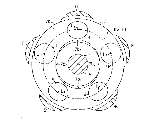
referring to Figs. 1 through 4. As shown in Fig. l, a rotary
shaft 3 is rotatable supported via bearings 4 and 5 in a pair
.. :
of cylinder blocks 1 and 2 which are secured to each other.
A plurality of bores la and 2a (five each in this embodiment)
are respectively formed in the cylinder blocks l and 2 at
:
`~ equiangular distances on a plurality of axes L1 located on an
imaginary circumferential plane C0 around the axis, L0, of the
rotary shaft 3. Each bore la in the -front cylinder block 1
is paired with the associated bore 2a in the cylinder block
: .
2, thereby forming a plurality of cylinder bores. As shown ~ ;
~ in Fig. 2, a plurality of double-headed pistons 6 are
-~- reciprocally retained in the respective bores la and 2a. ~ ~-M
~ 6 ~ ~
:
.
A wave plate 7, secured to the rotary shaft 3, has cam
surfaces 7a and 7b formed with a predetermined width at the
front and rear portions of the wave plate 7. A pair of shoes
8 and 9 are provided between the wave plate 7 and each piston
6. The piston 6 has a pair of recesses 6a and 6b at the
center. The shoes 8 and 9 have first spherical surfaces 8a
and 9b, which are fitted in the respective recesses 6a and 6b,
and second spherical surfaces 8b and 9b, which slide on the
respective cam surfaces 7a and 7b of the wave plate 7. As
shown in Fig 3, the radius of curvature R1 of the second
spherical surfaces 8b and 9b is larger than the radius of
curvature R2 of the first spherical surfaces 8a and 9a. The
centers, Q1 and Q2, of th'e first spherical surfaces 8a and 9a
are located substantially at the centers of the second
spherical surfaces 8b and 9b.
The cam surfaces 7a and 7b of the wave plate 7 are located on
; a displacement curve F on the circumerential surface C0. The
displacement curve F is a 2-cycle displacement curve which has
four first portions alternately protruding forward and
rearward (leftward and rightward in Fig. 1) with respect to
a plane perpendicular to the axis L0 of the rotary shaft 3.
In addition, second portions are provided that link the four
first portions. Examples of the displacement curve F of the
cam surfaces 7a and 7b include a sinusoidal displacement curve
~;~ and a cycloicl displacement curve.
.~
- 7 -
-
For each revolution of the wave plate 7 makes, the piston 6
reciprocates twice. The reciprocation of the piston 6 causes
the refrigerant gas in a suction chamber 10 to enter the bores
la and 2a via inlet ports 12 and associated inlet valves 11.
The refrigerant gas in the bores la and 2a iq exhausted to a
discharge chamber 15 via discharge ports 14 and associated
discharge valves 13.
:` :
The cam surface 7a and 7b have cross sections on a plane
containing the axis L0 along an arc, which has the same radius ;~
of curvature as the radius of curvature R1 of the second -~
spherical surfaces 8b and 9b. Therefore, the second spherical
surfaces 8b and 9b of th'e shoes 8 and 9 have a line contact
with the cam surfaces 7a and 7b. Since the centers Q1 and Q2
of the first spherical surfaces 8a and 9a are located at the
; centers of the second spherical surfaces 8b and 9b, the
displacement of the piston 6 accurately reflects the
displacement of the cam surfaces 7a and 7b on the displacement ~ -
curve F of the cam 7. ;~
Fig. 4 illustrates the wave plate 7 turned 90 degrees from the
position in Fig. 3. As shown in Figs. 3 and 4, a pair of
rightmost portions 7al of the front cam surface 7a are
;~ arranged at an angular distance of 180 degrees from each
other. A pair of leftmost portions 7a2 are resp0ctively ~ -
separated from the pair of rightmost portions 7al by 90
degrees. A leftmost portion 7bl of the rear cam surface 7b
- 8 -
.~ ':
, ~ .
. ~
,.--~
is located at the back of the leftmost portion 7a2 of the
front cam surface 7a. A rightmost portion 7b2 of the rear cam
surface 7b is located at the rear of the rightmost portion 7al
of the front cam surface 7a.
The rightmost portion 7al of the cam surface 7a is used for
driving the piston 6 toward the bottom dead center on the side
of the bore la. The leftmost portion 7a2 of the cam surface
7a is used for driving the piston 6 toward the top dead center
on the side of the bore la. The leftmost portion 7bl of the
cam surface 7b is used for driving the piston 6 toward the
bottom dead center of the piston 6 on the side o the bore 2a.
The rightmost portion 7b~ of the cam surface 7b is used for
driving the piston 6 toward the top dead center of the piston
6 on the side of the bore 2a.
The leftmost portion 7a2 ~corresponding to the top dead
center) of the cam surface 7a is located on a circle Ca2
indlcated by a chain line in Fig. 3. The leftmost portion 7bl
~corresponding to the bottom dead center) of the cam surface
7b is located on a circle Cbl and is also indicated by a chain
line in Fig 3. The rightmost portion 7al (corresponding to
the bottom dead center) of the cam surface 7a is located on
a circle Cal as indicated by a chain line in Fig. 4. The
rightmost portion 7b2 (corresponding to the top dead center)
~: .
of the cam surface 7b is located on a circle Cb2 and is
similarly indicated by a chain line in Fig. 4. The circles
g _
., ~
:.
Cal, Ca2, Cbl and Cb2 have the same ra.dius.
The centers, Pal and Pbl, of the circles Cal and cbl lie
outside the axis Ll of the piston 6, and the centers, Pa2 and
Pb2, of the circles Ca2 and Cb2 lie on the axis L1 of the
piston 6. That is, a normal vector Val on the displacement
curve F at the rightmost portion 7al (the bottom-dead-center
portion, hereinafter referred to BDC portion) of the cam
surface 7a is inclined outward with respect to the axis L0 of
the rotary shaft 3. A normal vector Va2 on the displacement
curve F at the leftmost portion 7a2 (the top-dead-center
portion, hereinafter referred to TDC portion) of the cam
surface 7a is parallel to the axis L0 of the rotary shaft 3.
'~ A normal vector Vbl on the cycle displacement curve F at the
leftmost portion 7bl tthe BDC portion) of the cam surface 7b
i9 inclined outward with respect to the axis L0 of the rotary
shaft 3. A normal vector Vb2 on the displacement curve F at
~: the rightmost portion 7b2 (the TDC portion) of the cam surface ` 7b is parallel to the axis L0 of the rotary shaft 3.
A normal vector on the displacement curve F of the cam surface
':
~:~ 7a is gradually inclined outward, with respect to the axis L0 --; :
:~: between the TDC portion 7a2 and the BDC portion 7al as the
;~ normal vector position is shifted toward the BDC portion 7al
from the TDC portion 7a2. Likewise, a-normal vector on the
displacement curve F of the cam surface 7b is gradually~. ~
' inclined outward with respect to the axis L0 between the TDC : -
:~,
-:
~r -
portion 7b2 and the BDC portion 7bl as the vector position is
shifted toward the BDC portion 7bl from the TDC portion 7b2.
The radius of curvature Rl of the second spherical surfaces
5 8b and 9b of the shoes 8 and 9 is restricted by the radius of
curvature of the displacement curve F at the BDC portions 7al
and 7bl (indicated by rO in Fig. 4). If the normal vectors
at the BDC portions 7al and 7bl are parallel to the axis LO,
therefore, the radius of curvature Rl should be smaller than
the radius of curvature rO of the displacement curve F at the
BDC portions 7al and 7bl.
Since the normal vectors Val and Vbl at the BDC portions 7al
and 7bl are inclined outward with respect to the axis LO in
this embodiment, the radius of curvature R1 can be made
greater than the radius of curvature rO. The radius Rl of the
8DC portion 7bl is in fact ~et larger than the radius of
curvature rO as shown in Fig. 3. Given the above conditions,
an arc crossing between the circumferential surface cO and the
second spherical surface 9b and having a radius of curvature
"r", is smaller than the radius R1. As the inclination of the
normal vector Vbl increases, the radius of curvature ~r'
becomes smaller than the radius Rl.
If the radius of curvature "r" is larger than the radius of
curvature rO, the second spherical surface 9b is lifted
without contacting the BDC portion 7bl. If the radius of
curvature ~r" is equal to or smaller than the radius of
curvature rO, the second spherical surface 9b comes in line
contact with the BDC portion 7bl. By setting the radius of
curvature "r" equal to or smaller than the radius of curvature
rO and as close to this radius of curvature rO as possible,
the radius of curvature Rl of the second spherical surface 9b
of the shoe 9 becomes greater than the radius of curvature rO.
This would reduce the Hertz' Q pressure occurring between the
second spherical surface 9b and the cam surface 7b.
The radius of curvature of the second spherical surface 8b of
the shoe 8 can also be set greater than the radius of
curvature rO, thus reduc~ng the Hertz's pressure between the
second spherical surface 8b and the cam surface 7a. The
reduction in Hertz's pressure improves the pressure resistance
characteristics of the shoes 8 and 9 as well as the wave plate
7. This pressure reduction thus improves the durability of
the compressor. In this case, the radius of curvature Rl of
the second spherical surfaces 8b and 9b can be increased
without increasing the diameter of the piston 6 or the
diameter of the wave plate 7. It is therefore possible to
improve the durability of the compressor without enlarging the
compressor.
The present invention is not limited to the above-described
embodiment. For example, normal vectors Vcl and Vdl at BDC
portions 7cl and 7dl of cam surfaces 7c and 7d may be inclined
- 12 -
.. " ,,'~ ',,
~^ -
inward with respect to the axis LO as shown in Figs. 5 and 6.
Normal vectors Vc2 and Vd2 at TDC portions 7c2 and 7d2 of the
cam surfaces 7c and 7d are parallel to the axis LO. Fig. 6
illustrates the wave plate 7 turned 90 degrees from the
5 position in Fig. 5. Even in the case where the normal vectors
Vcl and vdl are inclined inward with respect to the axis LO,
the radius of curvature R1 of the second spherical surfaces
8b and 9b can be set greater than the radius of curvature rO
of the displacement curve F at the BDC portions 7cl and 7dl.
Further, normal vectors Vel and Vfl at BDC portions 7el and
7fl of cam surfaces 7e and 7f may be inclined outward with
respect to the axis LO. Normal vectors Ve2 and Vf2 at TDC
portions 7e2 and 7f2 may be inclined inward with respect to
the axis LO, as shown in Figs. 7 and 8. Fig~ 8 illustrates
the wave plate 7 turned 90 degrees from the position in Fig.
7.
~ :,
Furthermore, normal vectors Vg and Vh at all the points on the
displacement curve F on cam surfaces 7g and 7h may be inclined
outward with respect to the axis LO of the rotary shaft as
shown in Figs. 9 and 10. Fig~ 10 illustrates the wave plate
,.
7 turned 90 degrees from the position in Fig. 9.
~` 25 AB shown in Figs. ll(a), ll(b) and 12, both the first surfaces
16a and 16b of shoes 16 and 17, which are to be fitted in a
- pistorl, and the second surfaces 16b and 17b of the shoes,
- 13 -
.
which slide on the wave plate 7, may be designed with a
cylindrical shape. In this ~ase,, both the cam surfaces 7i and
7j of the wave plate 7 that lie on a plane containing the axis
L0 of the rotary shaft, and the second surfaces 16b and 17b
that lie on the same plane have respectively cross sections
along a straight line. The first surfaces 16a and 17a slide
in contact with the cylindrical inner walls of recesses 6c and
6d of the piston. The shoes 16 and 17 are rotatable within
a plane containing the axis L0 of the wave plate 7.
The second surfaces 16b and 17b are therefore always in line
contact with the cam surfaces 7i and 7j, even if the normal
vector Vj at the BDC portion 7jl is inclined with respect to
both the axis L0 of the rotary shaft while the normal vector
vi at the TDC portions 7i2 and 7j2 are parallel to the axis
L0.
The shoes 16 and 17, when cut along a plane perpendicular to
the lengthwise direction of the second surfaces 16b and 17b,
have semicircular cross sections. If the second surfaces 16b
and 17b of the shoes 16 and 17 located at the BDC portion 7jl
of the cam surface 7j, are cut at the circumferential surface
C0, the cross sections are semi-elliptic. The curvature of
this semi-el1iptic cross section on the displacement curve F
is greater than the curvature of the semicircular cross
section. It is therefore possible to set the radius of
curvature of the second surfaces 16b and 17b greater than the
14
radius of curvature rO of the di,3placement curve F at the BDC
portion 7jl. This reduces the Hertz's pressure between the
shoes 16 and 17 and the cam surfaces 7i and 7j.
The cam surfaces may be formed in a convex shape, and the
second surfaces of the shoes, which engage with the cam
surfaces, may be formed in a concave shape.
'
~ 15
~ ;~